1988 THM 700-R4 TRANSMISSION NEW PRODUCT INFORMATION

1988 THM 700-R4 (MD8) TRANSMISSION - NEW PRODUCT INFORMATION
MODELS AFFECTED: 1988 FIREBIRD
BULLETIN COVERS:
The information contained in this bulletin describes changes that have occurred in the 1988 THM 700-R4 transmission. Refer to each section of this bulletin for specific product change information.
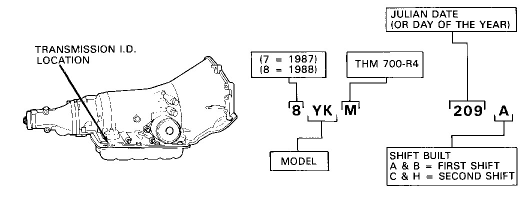
DATE OF PRODUCTION CHANGE: (Figure 1) -------------------------- Beginning with the Start of Production 1988, all 1988 THM 700-R4 transmissions were produced with the product changes listed in this bulletin.
SERVICE MANUAL REFERENCE:
Product changes in this bulletin that are included in your 1988 THM 700-R4 Unit Repair Service Manual are identified by an asterisk in the 1988 Unit Repair Table of Contents.
SUBJECT: -------- New Control Valve Assembly
VEHICLE APPLICATION:
Firebird Models
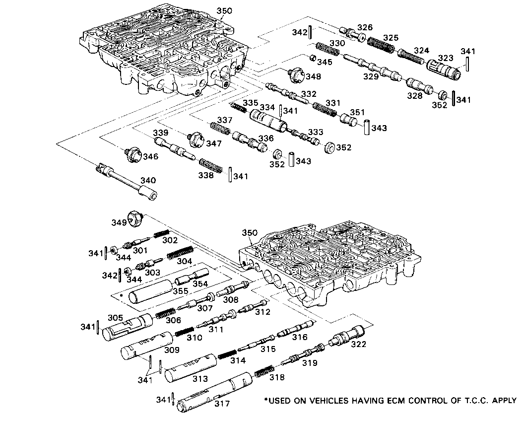
Change To Assembly Components: (Figure 2) ------------------------------ A new Control Valve Assembly (67) and Valve Body Spacer Plate for all 1988 THM 700-R4 transmissions. The new Control Valve Assembly consists of revised 1-2 and 3-4 shift valve trains. With the change to the 1-2 valve train, two valves and one sleeve have been eliminated. The lo range downshift valve (321), the lo range control sleeve (320) and the 1-2 lo range upshift valve (353) have been eliminated from the 1988 THM 700-R4 Control Valve Assembly.
These new valve trains improve consistency for the 1-2 and 3-4 shifts.
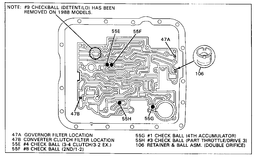
With the changes made to the control valve assembly, the #9 Lo-Detent Checkball has been eliminated from 1988 THM 700-R4 transmissions.
Service Action: (Figure 3) --------------- A 1988 Control Valve Assembly CANNOT be used on any past model THM 700-R4 transmission. In addition, when servicing a 1988 THM 700-R4 transmission, DO NOT install a #9 checkball in the case.
Installing a #9 checkball in a 1988 model case could cause the lo and reverse clutch to burn.
Service Manual Reference:
This material is included in your 1988 Service Manual Unit Repair Section. All material that is new for 1988 or was not included in your 1987 Service Manual is noted by an asterisk in the 1988 Unit Repair Table of Contents.
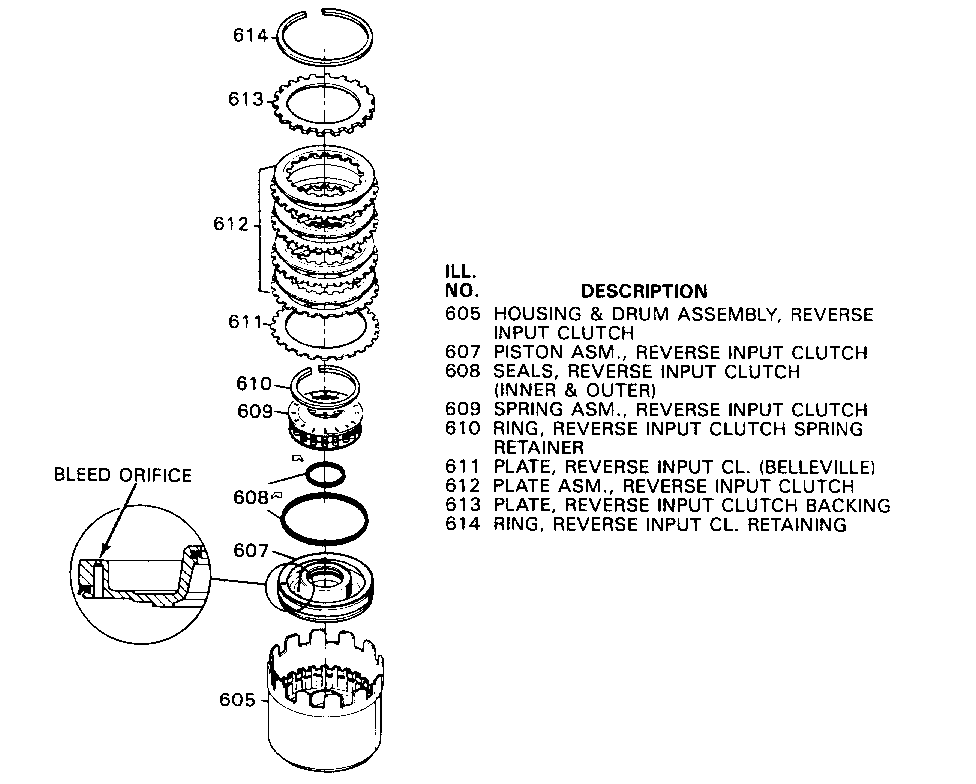
SUBJECT: -------- New Input Clutch Assembly With 3-4 Clutch Boost Springs
VEHICLE APPLICATIONS:
Firebird Models
TRANSMISSION MODELS:
YDM, YMM, YWM And YZM
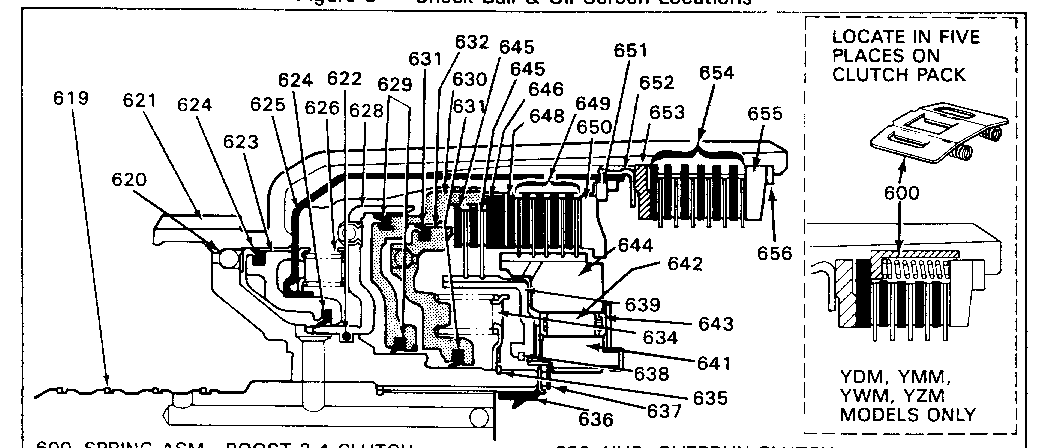
Change To Assembly Components: (Figure 4) ------------------------------ A new Input Clutch Assembly with 3-4 boost springs (600) added for the 1988 THM 700-R4 transmission YDM, Ymm, Ywm and YZM models. The boost springs quicken the release of the 3-4 clutch on downshifts.
Service Action:
When servicing a 1988 THM 700-R4 transmission model YDM, Ymm, Ywm or YZM, the 3-4 boost springs must be installed. Improper shift timing can occur if these springs are not installed.
NOTICE: The 3-4 clutch boost springs CANNOT be used on any THM 700-R4 transmission produced prior to the 1988 model year, or any 1988 THM 700-R4 transmission other than the YDM, Ymm, Ywm or YZM models.
Service Parts Information:
Part Number ------ 8667424 Spring Asm, Boost 3-4 Clutch (600) - (5 required)
Service Manual Reference:
This material is included in your 1988 Service Manual Unit Repair Section. All material that is new for 1988 or was not included in your 1987 Service Manual is noted by an asterisk in the 1988 Unit Repair Table of Contents.
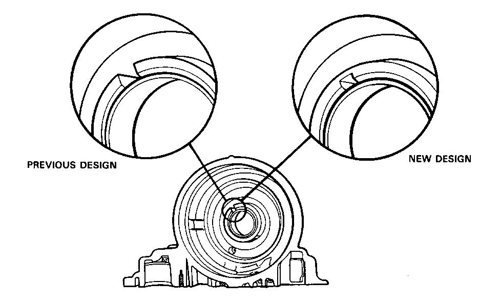
SUBJECT: -------- Case Die Change - Slot At The Lo And Reverse Case Hub
VEHICLE APPLICATIONS:
Firebird Models
Change To Assembly Components: (Figure 5) ------------------------------ The slot located in the case hub at the lo and reverse piston no longer extends through the hub. The change in the case eliminates the possibility of a burr, on the inside edge of the slot, from cutting the lo and reverse piston inner seal during installation.
Date Of Production Change:
The case dies began change over during late 1987 production and were completed early in the 1988 model year.
Service Action:
When servicing the lo and reverse piston on 1987 and prior model transmissions it was possible to remove the lo and reverse clutch retaining ring with a screw driver through the slot. With the new case change, the slot does not extend through the case hub so the retaining ring is not accessible with a screwdriver. To remove the lo and reverse piston, compress the lo and reverse clutch spring assembly and using Snap Ring Remover/Installer, Kent Moore tool number J-34627, remove the retaining ring.
Service Manual Reference:
This material is NOT included in your 1988 Service Manual Unit Repair Service.
General Motors bulletins are intended for use by professional technicians, not a "do-it-yourselfer". They are written to inform those technicians of conditions that may occur on some vehicles, or to provide information that could assist in the proper service of a vehicle. Properly trained technicians have the equipment, tools, safety instructions and know-how to do a job properly and safely. If a condition is described, do not assume that the bulletin applies to your vehicle, or that your vehicle will have that condition. See a General Motors dealer servicing your brand of General Motors vehicle for information on whether your vehicle may benefit from the information.
