SERVICE MANUAL UPDATE SEC. 8A ELECTRICAL DIAGNOSIS

SUBJECT: MANUAL UPDATE SECTION 8A ELECTRICAL DIAGNOSIS (ADD'L PROCEDURES FOR CONVERTIBLE TOP)
VEHICLES AFFECTED: INTERIM 91 PRODUCTION PONTIAC FIREBIRD
The 1991 Pontiac Firebird Service Manual does not contain service procedures for the convertible top. To service the convertible top perform procedures on the attached pages.
SECTION 8A ELECTRICAL DIAGNOSIS FIREBIRD
Cell Index 110 Exterior Lights 114 interior Lights 121 Convertible Tonneau Release Page Convertible Tonneau Release................. 121-0 Lights (Exterior) .......................... 110-2 High Level Stop ......................... 110-2 Lights (Interior) Cargo Compartment........................ 114-2 Cigar Lighter............................ 114-0 Courtesy ................................ 114-0 Glove Box ............................... 114-0 Map/Dome ................................ 114-0
TROUBLESHOOTING HINTS
Note: This section does not address conditions with the operation of the Daytime Running Lights. If the exterior lights work with the Light Switch, but do not operate automatically, see section BA-104.
o Try the following checks before doing the System Diagnosis.
Turn Lights
1. Check the TURN B/U Fuse by operating Back Up Lights.
2. If only some of the Turn Lights work but all of the Hazard Lights work, replace the Turn-Hazard Switch.
3. If the Left Turn or Right Turn lights flash slowly or turn on other lights, check the ground wires and check that G103, G104 and G303 are clean and tight.
4. If the Turn Lights stay on (do not flash) in both Left Turn and Right Turn, replace the Turn Flasher.
5. If only one light does not light, check the bulb, socket and related wiring (see schematic).
6. On vehicles equipped with Daytime Running Lights (T6 1), if the Front Turn Lights do not operate in the daytime (Light Switch is OFF) but operate correctly at night (Light Switch in HEAD), see section 8A- 104.
Stop Lights
1. Check the STOP HAZ Fuse by operating Hazard Lights.
2. If no Stop Lights work, check the Brake Switch and ORN (140) wire for continuity (see schematic). (Continued on next page)
COMPONENT LOCATION Page-Figure* --------------------- ------------- Brake Switch............Top of brake pedal support.................. 201-14-B Convenience Center......Behind I/P, to right of steering column..... 201-12-C Daytime Running Lts (DRL) Module.................Behind LH side of I/P, near Fuse Block...... 201-12-A Fuse Block..............Behind LH side of I/P....................... 201-12-B Headlight Door Module...LH front of dash ........................... 201-10-B Turn Flasher ...........Behind I/P, clipped to side of fuse block bracket................................... 201-12-B Turn Hazard Switch .....Top of steering column C 100 (42 cavities).....LH front of dash .......................... 201-10-A C208 (8 cavities) .....LH rear corner of cargo compartment......... 201-19-C C2 10 (11 cavities).....Behind LH side of I/P, on steering column... 201-13-A C216 (4 cavities).......LH shroud, near center access hole.......... 201-16-F C217 ...................CHMSL harness, near LH decklid hinge C312 (2 cavities).......Rear lights harness, near license plate .... 201-19-A G103 ...................Behind LH headlights........................ 201-11-A G104 ...................Behind RH headlights........................ 201-11-A G200....................Behind LH side of I/P, on convenience center bracket................................... 201-12-C G302....................Under headliner, near dome light ........... 201-16-F G303....................Center of rear end panel, in cargo compartment............................... 201-19-B S105....................Front lights harness, behind LH hdlts ...... 201-11-A S125....................Front lights harness, behind LH hdlts ...... 201-11-A S126....................Front lights harness, behind RH hdlts ...... 201-11-A S227....................I/P harness, near convenience center........ 201-12-A S236....................I/P harness, behind LH side of I/P.......... 201-12-A S237....................I/P harness, behind LH side of I/P, near fuse block..................................... 201-12-B S307....................Body rear harness, LH rear corner of cargo compartment............................... 201-19-C S308....................Body rear harness, near LH turn signal...... 201-19-A S311....................Body rear harness, near RH turn signal...... 201-19-A S375....................Body rear harness, LH rear corner of cargo compartment ............................. 201-19-C
*Page-Figure references are to 1991 Firebird Service Manual.
3. If the Stop Lights do not turn off, adjust/ replace the Brake Switch as necessary.
4. If only one light does not light, check bulb, socket and related wiring (see schematic).
Hazard Lights
1. Check the STOP HAZ Fuse by operating the Stop Lights.
2. If only some Hazard Lights work but all of the Turn Lights work, replace the Turn- Hazard Switch.
3. If Hazard Lights do not turn off, replace the Turn-Hazard Switch.
4. If Hazard Lights stay on (do not flash), replace Hazard Flasher.
Park/Marker/Tail/License Lights -------------------------------- 1. If the Park, Marker and Tail Lights do not work, check the TAIL Fuse, Light Switch, and BRN (9) wires for continuity (see schematic).
2. If Front Marker and Park Lights do not work, check connection at C100 and related wiring (see schematic).
3. If the Park, Marker and License lights do not turn off, disconnect the Daytime Running Lights (DRL) Module connector C1 (with T6 1). If the lights turn off replace the DRL Module. If the lights remain on, or without T61, disconnect the Light Switch. If the lights remain on, check for a short to battery in the BRN (9) wire. Go to System Diagnosis for diagnostic tests.
SYSTEM DIAGNOSIS
o Do the tests listed for your symptom in the Symptom Table below.
o Tests follow the Symptom Table.
SYMPTOM TABLE
SYMPTOM FOR DIAGNOSIS ----------------------------------- ------------------- Turn Lights do not work, but Hazard A: Turn Lights Test Lights do
Hazard Lights do not work, but the B: Hazard Lights Test Turn Lights work
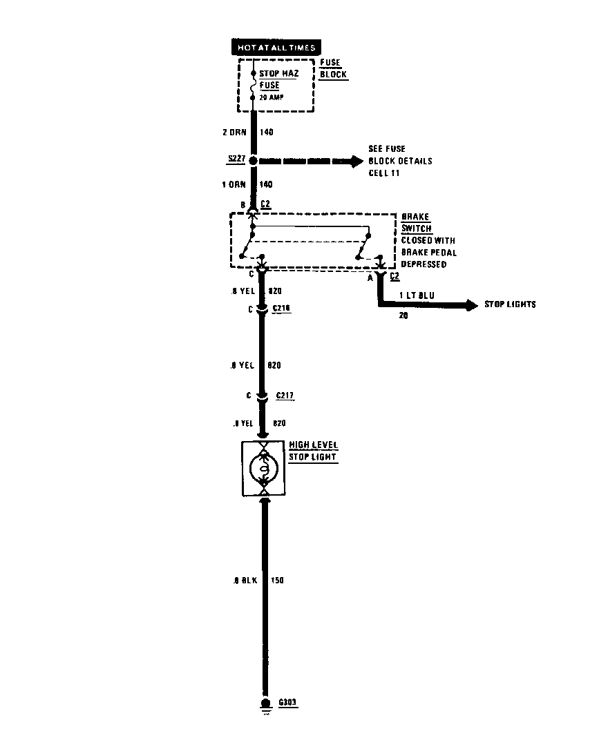
High Level Stop Light does not work C: Stop Lights Test
Stop Lights on one or both sides do not C: Stop Lights Test work
A: TURN LIGHTS TEST -------------------- Connect: TEST LAMP At: CONNECTOR C210 (Connected) Condition: o Ignition Switch: RUN
Connect Correct Result For Diagnosis Between --------- --------------- ----------------- L(PPL) & Lamp lights See 1 Ground
If the test lamp lights, replace the Turn - Hazard Switch.
1. Check the Turn Flasher and PPL (16) wire for an open.
B: HAZARD LIGHTS TEST (TABLE 1) ------------------------------- Connect: FUSED JUMPER At: CONVENIENCE CENTER Conditions: o Hazard Flasher: REMOVED o Hazard Switch: HAZARD
Jumper Correct Result For Diagnosis Between ------------ -------------- -------------- M (ORN) & N All Turn See 1 (BRN) Lights turn on
If result is correct, replace Hazar Flasher.
1. Go to Table 2.
B: HAZARD LIGHTS TEST (TABLE 2) --------------------------------- Measure: VOLTAGE At: Connector C210 (Disconnected) Condition: o Hazard Flasher: CONNECTED
Measure Correct For Diagnosis Between Voltage ---------- ------- --------------- K (BRN) & Battery See 1 Ground
o If voltage is correct, replace the Turn- Hazard Switch.
1. Check ORN (140) and BRN (27) wires for opens.
C: STOP LIGHTS TEST (TABLE 1) ------------------------------ Connect: TEST LAMP At: CONNECTOR C208 (Disconnected) Condition: o Brake Pedal: DEPRESSED
Connect Correct Result For Diagnosis Between ------------- -------------- ------------- B (LT BLU) & Lamp lights See 1 Ground
o If the results are correct, check bulbs, sockets and related wiring for opens.
1. Check the Brake Switch, LT BLU (20) and ORN (140) wires for continuity. Repair/ replace as necessary.
C: STOP LIGHTS TEST (TABLE 2) ------------------------------ Connect: TEST LAMP At: HIGH LEVEL STOP LIGHT CONNECTOR (Connected) Condition: o Brake Pedal: DEPRESSED
Connect Correct Result For Diagnosis Between -------- ---------------- --------------- (YEL) & Lamp lights See I (BLK)
o If voltage is correct, check bulbs, sockets and related wiring for opens.
1. Check the Brake Switch, YEL (820), ORN (140) and BLK (150) wires for continuity. Repair/replace as necessary.
CIRCUIT OPERATION
Turn Lights
With the Ignition Switch in RUN, BULB TEST or START, voltage is applied through the TURN B/U Fuse and Turn Flasher to the normally closed pole of the Hazard Switch in the Turn-Hazard Switch.
With the Turn Switch in TURN LEFT position, voltage is applied from the Turn Switch through the LT BLU wires to the LH Turn Indicator and the LH Front Park/Turn Light. Voltage is also applied through the YEL wires to the LH Rear Turn Lights. On vehicles with Daytime Running Lights, voltage is applied to connector C 1, pin E, of the DRL Module. The module controls the LH Front Turn Lights. See section 8A- 104 for operation of the DRL Module.
The Turn Lights go on immediately. They begin to flash when the current flow heats up the timing element in the Turn Flasher and it repeatedly opens and closes the circuit.
When voltage applied to the LH Front Park/ Turn Light, voltage will also be applied to the LH Front Marker Light (without T61). If the Light Switch is OFF, current will flow to ground through S 105 and the many lights connected in parallel to ground. These lights provide low resistance paths to ground. The Marker Light will flash with the Turn Lights. The lights used for the ground path will not flash, however, since the voltage drop across the Marker Light is much higher than that across the other lights.
When the Light Switch is in either PARK or HEAD, voltage is applied through the TAIL Fuse, Light Switch, and S105 to the Marker and Park Lights. If the Turn-Hazard Switch is in TURN LEFT, the LH Front Marker Light has battery voltage at both terminals and goes out. When the flasher stops supplying voltage to the Turn Light, the Marker Light is grounded through the Turn Light and goes on. In this way, the LH Front Marker flashes on when the LH Front Park/Turn Light goes off, and off when the Turn Light goes on.
With Daytime Running Lights (T61) the Front Marker Lights do not flash with the Turn Lights. Only the Tum Lights will flash with the Turn-Hazard Switch in TURN LEFT.
With the Turn-Hazard switch in TURN RIGHT, voltage is applied to the RH Lights in a similar way.
Hazard Lights
Voltage is applied at all times through the STOP HAZ Fuse and the Hazard Flasher to the normally open poles of the Hazard Switch in the Turn-Hazard Switch. With the Hazard Switch in HAZARD, current flows through the assembly using all four paths used by both Front and Rear Turn Lights. All of the Turn Lights and both Turn Indicators flash on and off.
The Front Marker Lights flash in HAZARD just as they did in TURN RIGHT and TURN LEFT (without T61). If the Light Switch is in OFF, they flash on when the Hazard Lights are on. If the Light Switch is in either PARK or HEAD, they flash on when the Hazard Lights are off, and off when the Hazard Lights are on.
With Daytime Running Lights (T61) the Front Marker Lights do not flash with the Turn Lights. Only the Turn Lights will flash with the Turn-Hazard Switch in HAZARD.
In HAZARD, the turn circuit is always open, and the Hazard Flasher controls the lights.
Stop Lights
Voltage is applied at all times through the STOP HAZ Fuse to the Brake Switch. When the brake pedal is depressed, the contacts in the Brake Switch close. Battery voltage is then applied to the Stop filament of the Tail-Stop Lights and to the High Level Stop Light. The Lights go on.
Front Park Lights
The Front Park Lights can be lit by putting the Light Switch either in PARK or in HEAD.
With the Park Lights or Headlights on, battery voltage is provided through the BRN wires to both Park Lights. The path to ground for the Park Lights is to G103 (LH) or G104 (RH).
The Park Lights will not flash when the turn signal is on, they will have a steady glow.
Front Marker Lights (Without T61)
The Front Marker Lights can be lit by the Park Lights or the Turn Lights. Neither of the two wires to each of the marker bulbs is a ground wire.
With the Park Lights on, battery voltage is supplied through the BRN wires to both Marker Lights. The path to ground for the marker bulbs is through the Turn Lights. The small Marker Light bulbs light up, but not the larger turn bulbs.
When the Turn Lights are on, but not the Park Lights, battery voltage is applied through the LT BLU (turn left) or DK BLU (turn right) wires to the Marker Lights. They flash since they are grounded through the entire Park Light system. As before, the small marker bulbs light up, but not all the parking bulbs.
If both the Park Lights and a set of Turn Lights are on at the same time, the marker bulb for that side will not light up. With battery voltage on both sides of a bulb, it will not glow. When the Turn Lights flash, however, the marker bulb on that side will come on since it is now grounded through the Turn Lights. This circuit makes the tum and marker bulbs flash out of step with each other when the Park Lights are on.
Front Marker Lights (With T61)
The Front Marker Lights can be lit by putting the Light Switch in PARK or HEAD. Voltage is provided through the BRN wires to each Front Marker Light. The ground path for the Marker Lights is to G103 (LH) or G104 (RH). The Marker Lights will not flash when the turn signal is on, they will have a steady glow.
License, Tail, or Rear Marker Lights
Voltage is applied through the TAIL Fuse to the Light Switch at all times. With the Light Switch in PARK or HEAD, voltage is applied through the fuse and the Light Switch to all of the lights in this circuit.
TROUBLESHOOTING HINTS
o Try the following checks.
1. Check the ACC Fuse by operating the Horns.
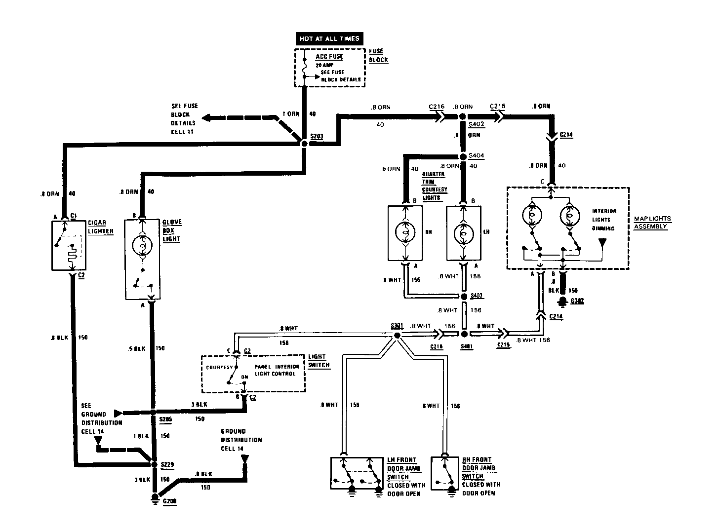
2. If only the Courtesy or Map Lights do not operate check the connection at C214, C215, C216 and related wiring for an open (see schematic).
3. If the Courtesy Lights do not turn off, check the Light Switch, LH and RH Door Jamb Switches and WHT (156) wire for a short to ground. Repair/ replace as necessary.
4. If only the Cigar Lighter does not work, check ORN (40) and BLK (150) wires for opens. Replace the Cigar Lighter if the wires are OK.
5. If only one light does not light, check bulb, socket and related wiring (see schematic).
6. If only the Glove Box Light does not work, check ORN (40) and BLK (150) wires for opens. Check the Glove Box Light switch.
COMPONENT LOCATION Page-Figure* ------------------- ------------- Fuse Block ..........Behind LH side of I/P ...................... 201-12-B C214 (4 cavities).....LH shroud, near center access hole........... 201-16-F C215 (4 cavities).....LH shroud, near center access hole C216 (4 cavities).....LH shroud, near center access hole G200..................Behind LH side of I/P, on convenience center bracket .................................. 201-12-C G302..................Under header garnish S203..................I/P harness, behind LH side of I/P............201-12-A S205..................I/P harness, behind LH side of I/P............201-12-A S229..................I/P harness, above Convenience Center........ 201-12-A S301..................I/P harness, behind LH side of I/P .......... 201-12-A S401..................Courtesy lamp harness, LH shroud near center access hole S402..................Courtesy lamp harness, LH shroud near center access hole S403..................Courtesy lamp harness, inside LH rocker conduit S404..................Courtesy lamp harness, inside LH rocker conduit
*Page-Figure references are to 1991 Firebird Service Manual.
CIRCUIT OPERATION
Voltage is applied at all times through the ACC Fuse to the components in the circuit. The Cigar Lighter, Glove Box Light and the Map Lights each use separate switches. The Courtesy Lights and Map Lights can be operated by providing a ground through the Light Switch to G200 or through any Door Jamb Switch to ground.
TROUBLESHOOTING HINTS
o Try the following checks before doing the System Check.
1. Check the LID Fuse by visual inspection.
2. Check the bulb by visual inspection.
3. Check that all connectors are firmly seated.
4. If the Cargo Compartment Light Switch does not function correctly, repair/replace it before repairing Cargo Compartment Light.
SYSTEM CHECK
o Use the System Check Table as a guide to normal operation.
o Refer to System Diagnosis for diagnostic steps.
SYSTEM CHECK TABLE
ACTION NORMAL RESULT ----------------- ----------------------------- Open the Decklid The Cargo Light turns on and remains on
Close the Decklid The Cargo Light turns off
SYSTEM DIAGNOSIS
Do the test indicated below if the Cargo Compartment Light does not function correctly.
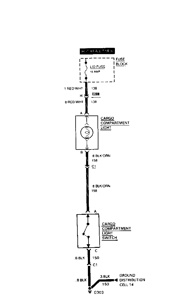
o If the Cargo Compartment Light does not light do Test 1.
o If the Cargo Compartment Light does not turn off do Test 2.
COMPONENT LOCATION Page-Figure* --------------------- ------------- Fuse Block .............Behind LH side of I/P................... 201-12-B Cargo Compartment ......Center of rear end panel, in cargo compartment Light Switch C208 (8 cavities).......LH rear corner of cargo compartment...... 201-19-C G303....................Center of rear end panel, in cargo compartment ................... 201-19-B C1 (3 cavities).........Center of rear end panel, in cargo compartment
*Page-Figure references are to 1991 Firebird Service Manual.
TEST 1
Measure: VOLTAGE At: CARGO COMPARTMENT LIGHT (Disconnected) Condition: o Decklid open
MEASURE CORRECT FOR BETWEEN VOLTAGE DIAGNOSIS ---------- ------- --------- RED/WHT & Battery See 1 Ground
RED/WHT & Battery See 2 BLK/ORN
o If all voltages are correct repair/replace, the Cargo Compartment Light.
1. Check RED/WHT (138) wire and LID Fuse for an open.
2. Check BLK/ORN (158) wire for an open. If OK, repair/replace the Cargo Compartment Light Switch.
TEST 2
Disconnect the BLK/ORN (158) wire from the Cargo Compartment Light Switch.
1. If the light remains on check the BLK/ORN wire for a short to ground.
2. If the light turns off repair/replace the Cargo Compartment Light Switch.
CIRCUIT OPERATION
Battery voltage is applied at all times from the LID Fuse to the Cargo Compartment Light. The light is controlled by the Cargo Compartment Light Switch switching the ground on or off.
When the Decklid is opened the Cargo Compartment Light Switch moves to the "unlatched" position. The Latch Switch completes the ground for the Cargo Light and it turns on.
When the hatch is pushed down the Latch Switch moves to the "latched" position, the ground path is opened and the Cargo Light turns off.
TROUBLESHOOTING HINTS
o Try the following checks before doing the System Diagnosis.
1. Check for proper operation of the Brake Warning System (manual transmission) or the Starting System (automatic transmission). Repair any conditions in those systems before attempting to diagnose conditions in the Hatch Release circuit.
2. Check the ACC Fuse by operating the horn.
o Go to System Check for a guide to normal operation.
o Go to System Diagnosis for diagnostic tests.
SYSTEM CHECK
Use the System Check Table as a guide to normal operation.
SYSTEM CHECK TABLE
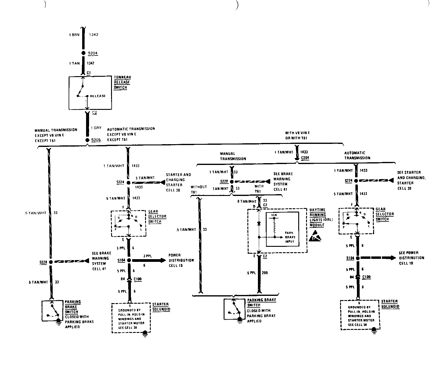
ACTION NORMAL RESULT -------------- ---------------- Press Tonneau Tonneau releases Release Switch and opens freely button with the Deck lid closed and the Parking Brake applied (manual transmission) or the Gear Selector Switch in P or N (automatic transmission)
SYSTEM DIAGNOSIS
o Do the test indicated below if the Tonneau Release does not operate properly.
COMPONENT LOCATION Page-Figure* -------------------- ----------- Daytime Running Lights (DRL) Module .....................Behind LH side of I/P .................201-12-A Fuse Block ...................Behind LH side of I/P .................201-12-B Gear Selector Switch..........In console, at gear selector......... 201-18-C Parking Brake Switch..........In console, at base of parking brake lever ........................ 201-14-E Starter Solenoid (VIN E) .....Lower RH side of engine................201-1-C Starter Solenoid (VIN F) .....Lower RH side of engine................201-7-B (VIN 8) Starter Solenoid (VIN T)......Lower RH side of engine................201-4-A Tonneau Release Relay.........RH side of console, behind gear selector................ 201-17-D Tonneau Rel. Solenoid No.1 ..Below tonneau panel Tonneau Rel. Solenoid No.2 ...Below tonneau panel Tonneau Rel. Switch.......... LH Tonneau Inboard Side C100 (42 cavities)............LH front of dash, below relay bracket. 201-12-A C203 (4 cavities).............Center of rear end panel, in cargo compartment C204 (I cavity)...............Behind center of I/P.................. 201-12-A S104 .........................I/P harness, behind LH side of I/P ... 201-12-A S203 .........................I/P harness, behind LH side of instrument cluster ........................... 201-12-A S204 .........................In console, behind center option panel S205 .........................In console, behind center option panel S224 .........................I/P harness, behind LH side of I/P, near Fuse Block..................... 201-12-A S228 .........................I/P harness, behind LH .. ............ 201-12-A side of I/P
*Page-Figure references are to 1991 Firebird Service Manual.
TEST 1
Measure: VOLTAGE At: TONNEAU RELEASE SWITCH CONNECTOR (Disconnected) Conditions: o Parking Brake (manual transmission): APPLIED o Gear Selector Switch (automatic transmission): P or N
MEASURE CORRECT FOR BETWEEN VOLTAGE DIAGNOSIS ---------- --------- --------- C1 (TAN) & Battery See I Ground
C1 (TAN) & Battery C2 (GRY) See 2
o Parking brake: RELEASED o Gear Selector Switch: D or R
C1 (TAN) & Approximately 0 See 3 C2 (GRY)
o If all voltages are correct, reconnect switch and go to Test 2.
1. Reconnect switch and go to Test 2.
2. Repair open in GRY (33 or 1433) wire.
3. Repair short to ground in GRY (33 or 1433) wire.
TEST 2
Measure: VOLTAGE At: TONNEAU RELEASE RELAY CONNECTOR (Disconnected) Conditions: o Parking Brake (manual transmission): APPLIED o Gear Selector Switch (automatic transmission): P or N
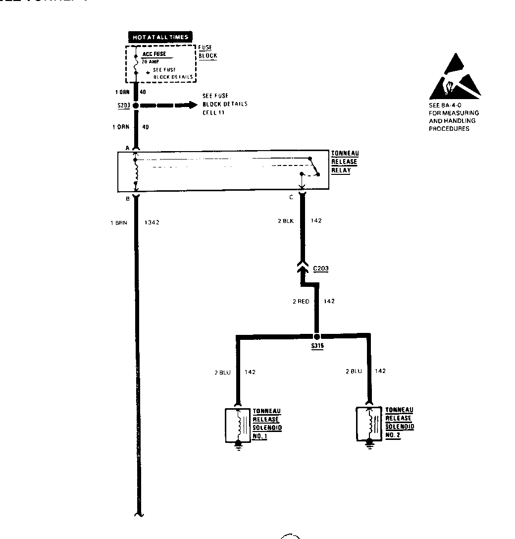
MEASURE CORRECT FOR BETWEEN VOLTAGE DIAGNOSIS --------- ------- ---------- A (ORN) & Battery See 1 Ground
o Tonneau Release Switch: RELEASE (hold closed)
A (ORN) & B Battery See 2 (BRN)
o If all voltages are correct reconnect relay and go to Test 3.
1. Check ORN (40) wire for an open.
2. Check BRN (1342) wire for an open. If wire and connectors are OK, replace the Tonneau Release Switch.
TEST 3
Measure: VOLTAGE At: EACH TONNEAU RELEASE SOLENOID CONNECTOR (Disconnected) Conditions: o Deck Lid: CLOSED o Parking Brake (manual transmission): APPLIED o Gear Selector Switch (automatic transmission): P or N o Tonneau Release Switch: RELEASE (hold closed)
MEASURE CORRECT FOR BETWEEN VOLTAGE DIAGNOSIS ------- ------- --------- BLU & Battery See 1 Ground
If voltage is correct, repair/replace the Tonneau Release Solenoid.
1. Check BLU (142) wire for an open.
CIRCUIT OPERATION
Voltage is applied at all times from the ACC Fuse to the Tonneau Release Relay. The relay is controlled by the Tonneau Release Switch grounding the relay coil. The Parking Brake must be applied, on vehicles with manual transmissions, to ground the relay coil. Vehicles with automatic transmissions use the starter, solenoid and motor to complete the ground.
When the relay is energized, voltage is applied to the Tonneau Release Solenoids. The solenoids operate the latches and the Tonneau panel opens.
General Motors bulletins are intended for use by professional technicians, not a "do-it-yourselfer". They are written to inform those technicians of conditions that may occur on some vehicles, or to provide information that could assist in the proper service of a vehicle. Properly trained technicians have the equipment, tools, safety instructions and know-how to do a job properly and safely. If a condition is described, do not assume that the bulletin applies to your vehicle, or that your vehicle will have that condition. See a General Motors dealer servicing your brand of General Motors vehicle for information on whether your vehicle may benefit from the information.
