WHITE POWDER COMING FROM HVAC VENTS DURING OPER. (REPL EVAP)

Subject: WHITE POWDER COMING FROM HVAC VENTS DURING OPERATION (REPLACE EVAPORATOR)
Models Affected: 1993 FIREBIRD MODELS
CONDITION:
--------- White dust or flakes can be emitted from the HVAC vents during operation.
CAUSE:
----- The dusting or flaking is caused by silicate coating flaking from the evaporator core. The flaking material is a non-crystalline silicone dioxide which represents no health or toxicity risk. This condition is initiated by usage of the A/C system including wetting and drying cycles of the evaporator core. The duration and amount of dust is variable and will disappear with time and usage. With regular A/C usage, some vehicles have stopped flaking within 2 or 3 days, although other vehicles may persist for several weeks.
CORRECTION:
---------- Replace the evaporator core with P/N 52467019. Replacement evaporator cores are not coated with silicate coating.
The following procedure is to be used in conjunction with the procedure in the Service Manual, Section 1B1.
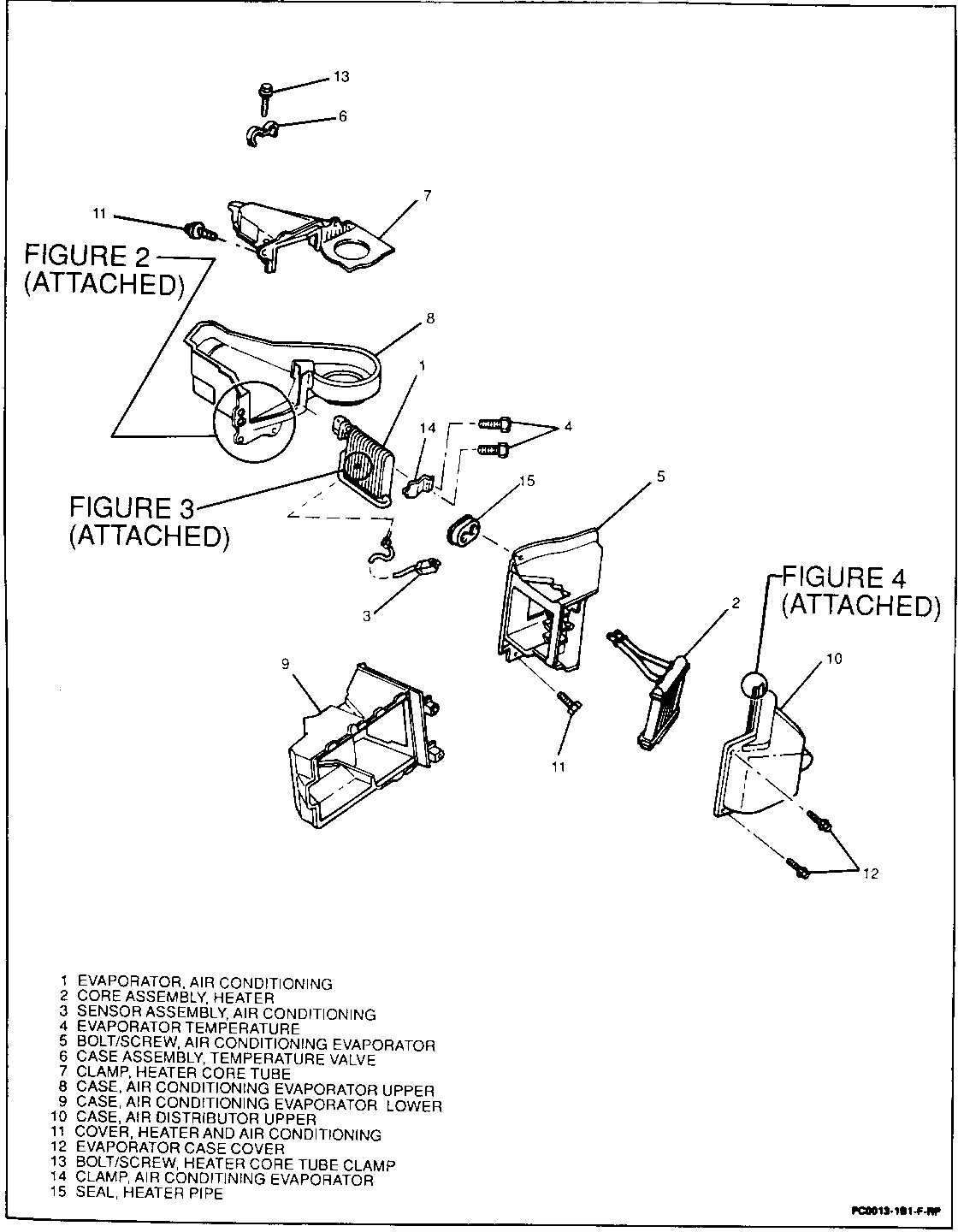
Figure 1 illustrates the Air Conditioning Evaporator and Components.
Note: Water can leak onto carpeting during this procedure, it is recommended that a mat be placed on passenger side floor.
1. Discharge A/C system with approved equipment per Service Manual.
2. Remove glove box.
3. Remove TXV (thermostatic expansion valve assembly) and foam seal around TXV back up block with knife.
4. Pry temperature sensing assembly from heater core cover with screw driver.
5. Remove temperature cable from bottom of temperature valve housing (1 screw).
6. Clamp off heater core lines, and remove clamps from heater pipes.
7. Remove heater core cover (2 screws) and heater core (i tube clamp and 1 screw (engine compartment) and 1 clamp and screw) per service Manual (Figure 1).
8. Remove temperature valve case assembly by removing 1 screw from engine compartment side and 2 screws from passenger side, slide case out and down.
Note: Disconnect vacuum harness from top of case during removal.
9. Remove 2 screws from bracket holding evaporator into module assembly.
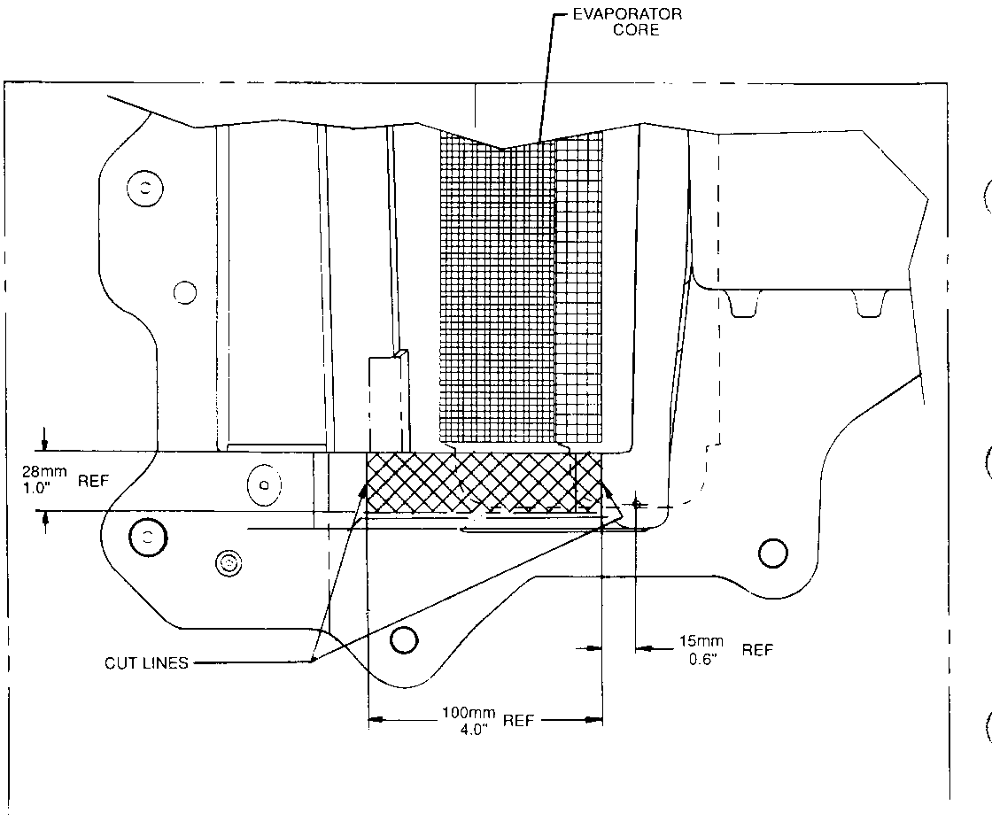
10. Using a hacksaw cut 2 vertical grooves each approximately 28 mm long (approximately 1 inch) in module assembly.
- Make right side vertical groove at 15 mm (approximately 0.6 inch) away from temperature valve case assembly screw. (Figure 1, screw #11).
- Make left side vertical groove 100 mm (approximately 4 inches) away from right side cut (Figure 2).
11. Carefully break vertical evaporator case wall between the two cuts by gently rocking back and forth with both hands. SAVE CUT AWAY PIECE, it will be epoxied back into place later in procedure.
IMPORTANT: This piece of material is required to keep condensate from draining inside vehicle.
12. Remove evaporator core through new opening of lower evaporator case.
CAUTION:
Approved safety glasses are required when performing the next step to reduce the chance of personal injury.
13. In addition to normal service procedure, the evaporator case and duct system should be thoroughly cleaned. With the evaporator out of the vehicle blow compressed air through the evaporator case to loosen any remaining dust that may be on the walls of the duct work and move it up towards outlet vents. Vacuum inside of evaporator case and any accessible ducts, then wipe with a damp cloth before installing evaporator.
14. Remove temperature sensing probe.
15. Remove water core filter from evaporator core (5 push pins).
16. Install new evaporator core gasket from service kit onto new evaporator core in the same position as original with appropriate adhesive.
17. Transfer condensate screen to new core with the same 5 push pins. Before installing, thoroughly rinse screen with water and be certain that there is no remaining silicate material. Make sure screen is in the same position as the original screen.
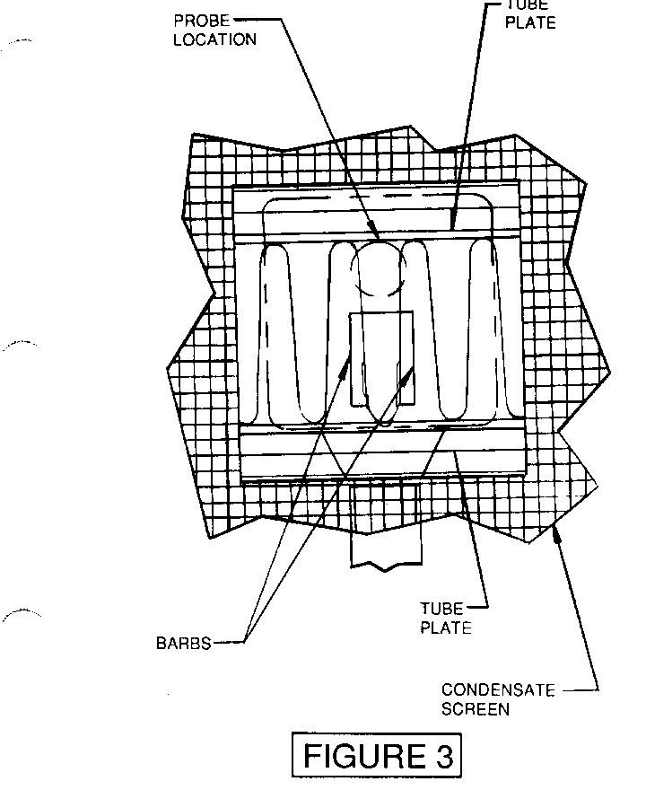
18. Re-install temperature probe into the new evaporator core (Figure 3).
IMPORTANT: Insure that the temperature sensing probe is fully seated against the face of the evaporator and is in contact with the evaporator tube plate.
19. Add 3 fluid ounces (90 ml.) of new polyalkylene glycol (PAG) synthetic refrigerant oil (GM P/N 12345923) to the outlet of the evaporator.
20. Install the new evaporator core into the air conditioning module assembly and secure to assembly with original bracket and 2 screws.
21. Loop the probe wire down and back up such that it is not tight across screen.
22. Replace vertical wall in evaporator case and epoxy into position. Use a general purpose two part epoxy with a 3 to 5 minute cure time. Hardman Fast Setting Epoxy (Order No. VOB-04001-10) or equivalent is recommended. Hardman Epoxy can be ordered through the following distributor:
V. 0. Baker Distributor 1-800-321-3572
After epoxy is dry, use thumb grade sealant on inside and outside to ensure water tight seal.
23. Using appropriate adhesive, position sealant on inside and outside to ensure water tight seal.
23. Using appropriate adhesive, position heater pipe seal onto temperature valve case. Place temperature valve case onto A/C module assembly per Service Manual using same 3 screws.
24. Use a sufficient amount of thumb grade sealant to ensure a water tight seal between the lower evaporator case and temperature valve case just installed.
25. Reinstall heater core per Service Manual. Ensure heater pipes are sealed to mating cases at the front of dash and use thumb grade sealant if required.
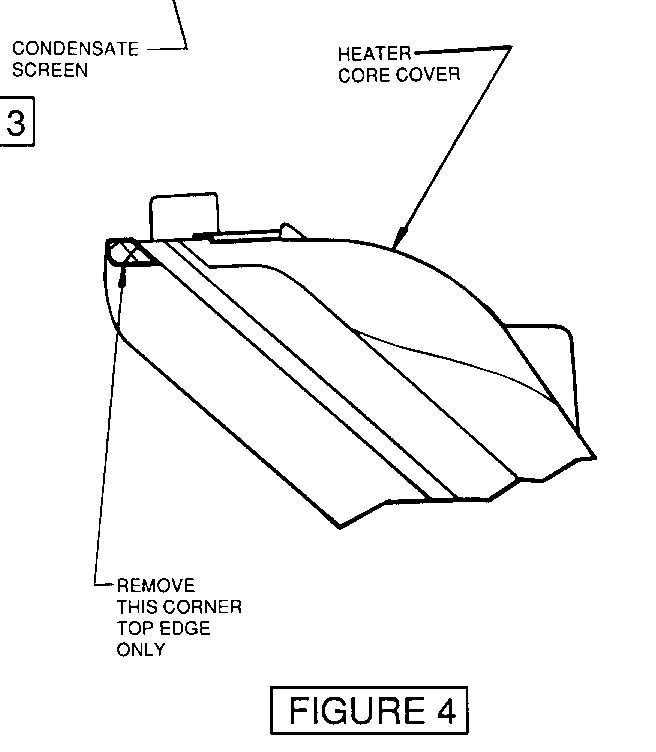
26. Trim heater core cover upper right side corner top flange 15 mm (approximately 0.6 inch) to ease cover installation (Figure 4). Heater core cover has a tongue and groove seal and must be engaged to seal properly.
27. Reinstall heater cover 2 screws and snap temperature sensor assembly onto cover.
28. Place appropriate refrigerant 0-Rings on the evaporator inlet and outlet pipes.
29. Re-install TXV with same 2 bolts and seal around back-up block to case with a sufficient amount of thumb grade sealant to provide a water and air tight seal.
30. Evacuate, charge refrigerant system with R-134a and leak check per Service Manual.
31. Re-fill coolant system as necessary with engine coolant per instructions in Service Manual.
32. After replacement of the evaporator core, the HVAC system should be cycled through all modes on high blower speed to dislodge any remaining particles. Thoroughly vacuum any surface of the vehicle where dust may have accumulated. Cleaning of the ducts and case is particularly critical in avoiding customer comebacks.
PART AVAILABILITY:
Parts are currently available from GMSPO.
WARRANTY INFORMATION:
Labor Operation: T3359
Labor Time: 2.8 Hrs.
Add to recover and recharge A/C 0.7 Hrs.


General Motors bulletins are intended for use by professional technicians, not a "do-it-yourselfer". They are written to inform those technicians of conditions that may occur on some vehicles, or to provide information that could assist in the proper service of a vehicle. Properly trained technicians have the equipment, tools, safety instructions and know-how to do a job properly and safely. If a condition is described, do not assume that the bulletin applies to your vehicle, or that your vehicle will have that condition. See a General Motors dealer servicing your brand of General Motors vehicle for information on whether your vehicle may benefit from the information.
