SERVICE MANUAL UPDATE-SEC. 8A & 9A VARIOUS INFO. UPDATES

Subject: SERVICE MANUAL UPDATE - SECTIONS 8A AND 9A VARIOUS INFORMATION UPDATES
Models Affected: 1993 FIREBIRD MODELS
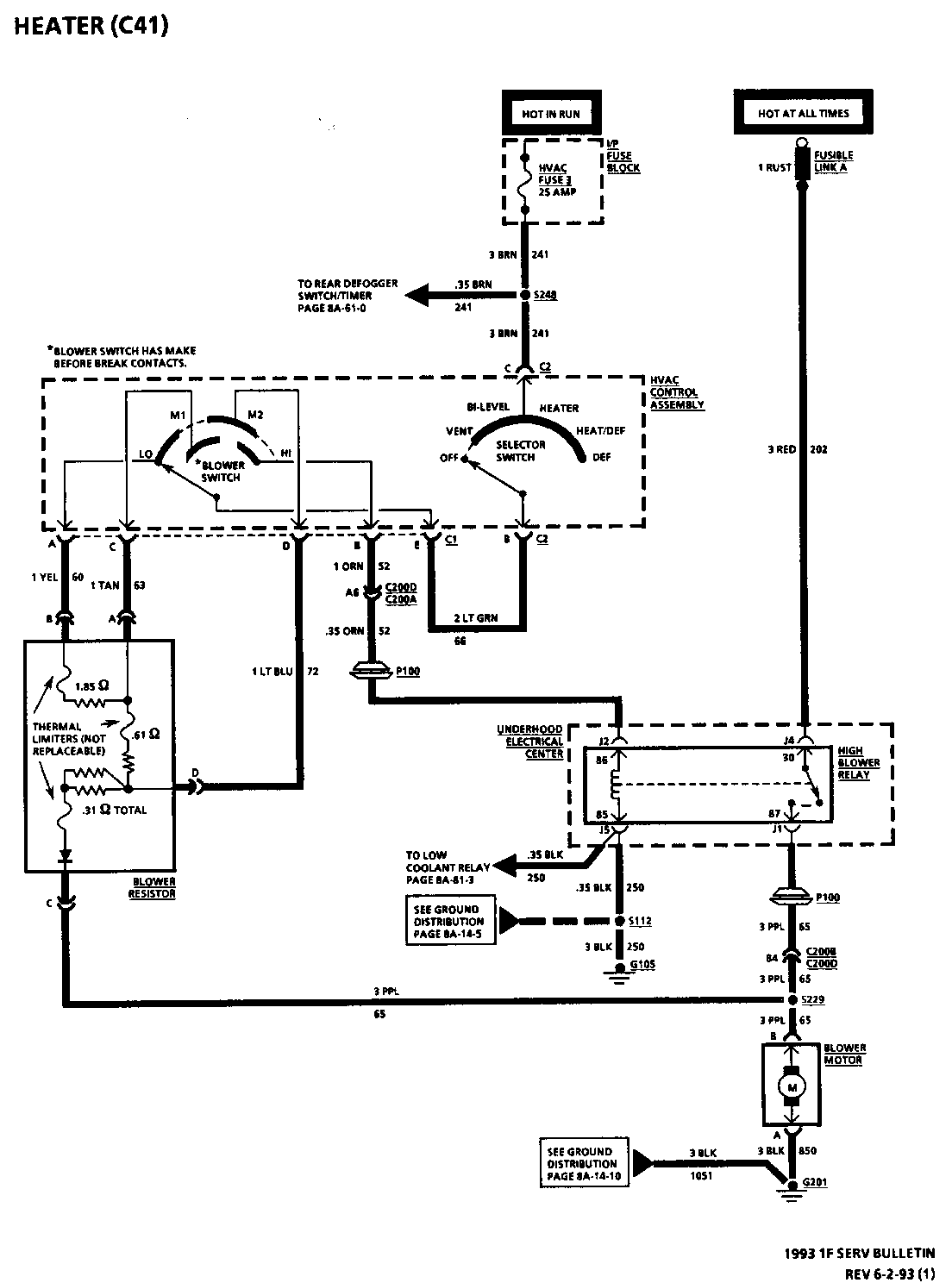
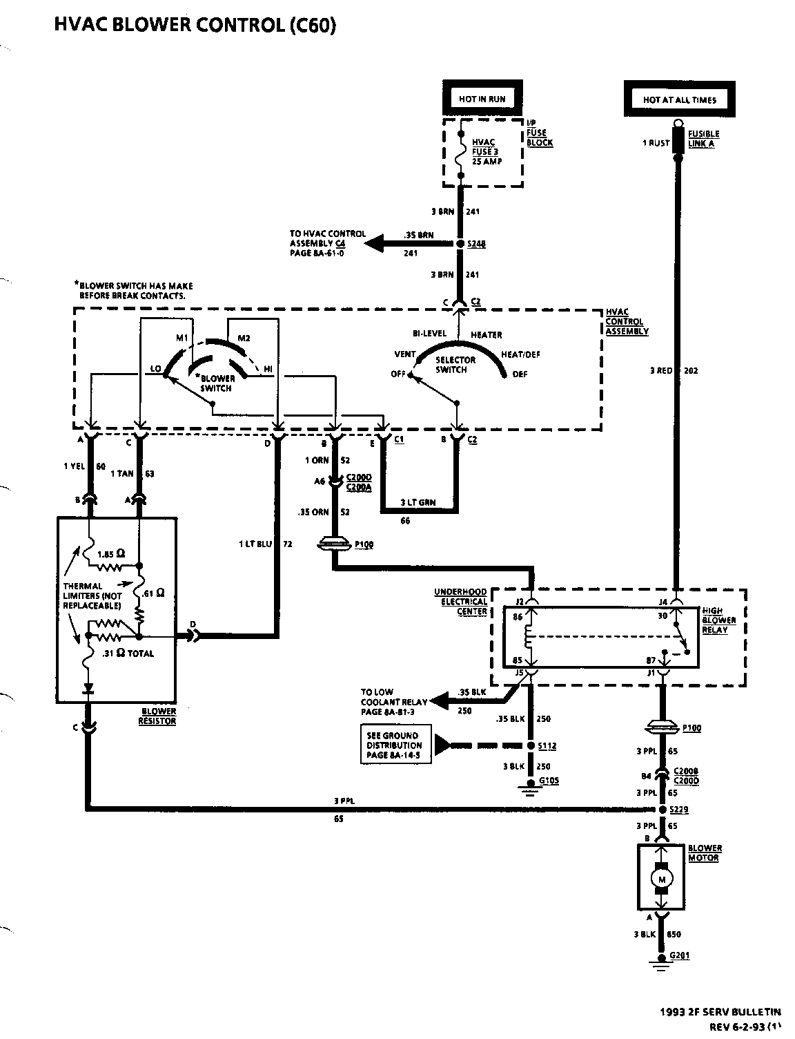
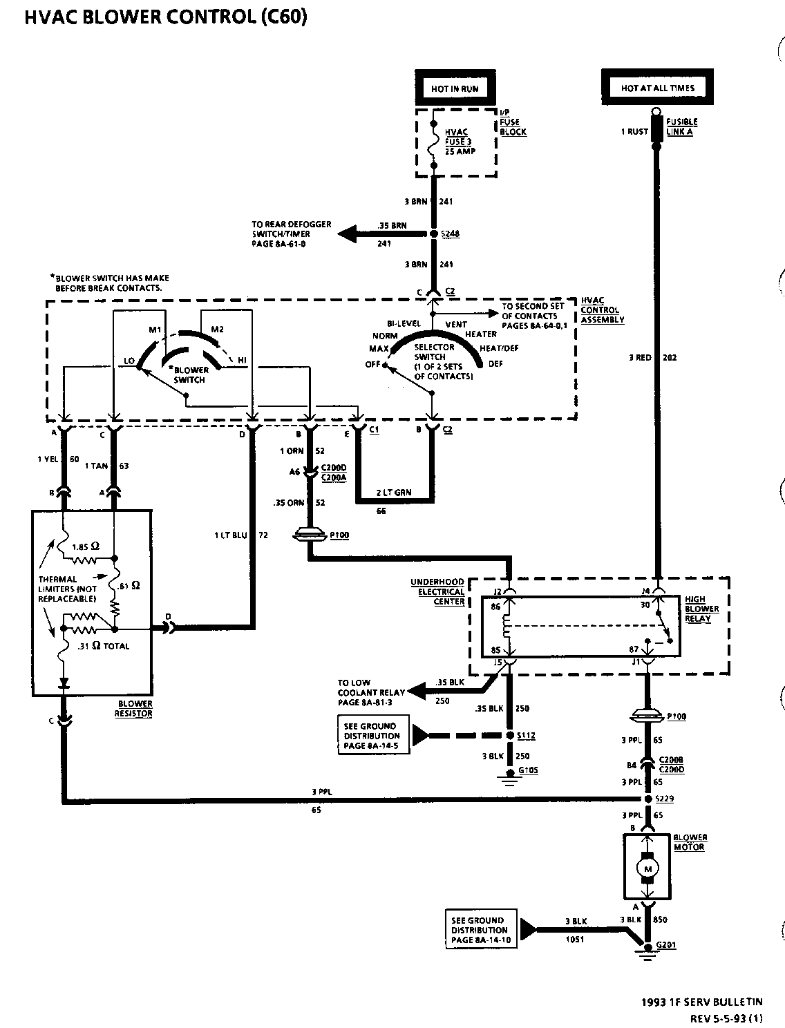
The schematic on pages 8A-60-0 and 8A-63-0 for Chevrolet and Pontiac are revised to illustrate a diode within the Blower Resistor.
The Lead-In Cable Resistance Value for Table 1 on page 8A-150-18 is revised from 0.2 ohms to 3.5 ohms for probing points A and B, C and D.
The Terminals on the Instrument Cluster Connector are revised on page 8A-30-1.
The Amperage Rating for the "Defog/Seats" and the "Windows" Circuit breakers are revised to 30 AMPS on several pages.
The setting and unlocking procedures for the Delco-Loc II Anti-Theft feature are revised on page 9A-6.
When replacing an In-Harness Diode, the chart below lists the proper GMSPO Replacement Diodes and their specifications recommended to be used for replacement of the diode(s) named in the Service Manual.
Amperage Peak Inverse Service Manual Name Rating Voltage GMSPO P/N ----------------------------------------------------------------------
A/C Clutch Diode 1 400 12112421 Isolation Diode (Low Coolant) 1 400 12112421 Isolation Diode (RAP) 3 400 12112422 Isolation Diode (Wipers) 3 400 12112422
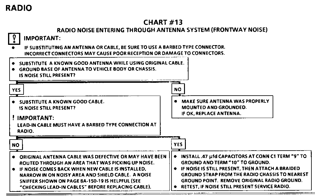
CHECKING RADIO MAST ANTENNAS
Unplug antenna lead-in at back of Radio and plug a test antenna into Radio. Make sure test antenna base is grounded to the vehicle chassis. Do not touch the mast. Check Radio reception in an area away from tall buildings, metal structures, power lines, fluorescent lighting and power tools. Tune to high and low ends of the dial on both AM and FM, checking weak and strong station reception. If reception is OK, the problem exists with antenna and/or its lead-in cable. If reception is still poor with test antenna, check for aftermarket equipment that may be causing complaint. If OK, service Radio.
CHECKING LEAD-IN CABLES
In case of continued reception or noise complaints, always check the lead-in with a digital multimeter, see Figure 3 and Table 1.
When checking resistance, cautiously wiggle the lead-in tip and cable. The previous readings should always be obtained. If not, some portion of the lead-in is intermittent and lead-in should be replaced. Also try:
1. Running a braided ground strap to the antenna lead-in.
2. Changing the antenna lead-in.
3. Disconnecting the lead-in to check resistance.
Table 1 - Lead-in Cable Resistance Values
Digital Multimeter Resistance measured probes at points: in ohms ------------------ ------------------- A and B less than 3.5 C and D less than 3.5 A and D infinite C and B infinite A and C infinite B and D infinite
"ST-PL:" (Stop/Play) -------------------- Press "ST-PL:" to stop disc from playing. The radio will resume playing. "ST-PL:" will also restart the disc. The disc will resume playing at the point where it stopped.
"EJCT", (Eject)
Push this to eject the disc and resume radio play.
SETTING DELCO-LOC II ANTI-THEFT FEATURE
Delco-Loc II is a security feature which can be used or ignored. If ignored, the radio assembly will play normally. If used, the radio assembly will be useless if stolen because it won't turn on.
This is how to enter a secret code into the radio assembly. If battery power is lost for any reason, the secret code must be entered again before the radio assembly will turn on.
1. Write down any 6-digit number and keep in safe place.
2. Turn ignition to "ACCESSORY" or "RUN" position.
3. Press "PWR" to turn radio assembly off.
4. Press "1" and "4" together and hold until shows on display.
5. Do not wait more than 15 seconds between each step.
6. Press "SET" and "000" appears on the display.
7. Press "SEEK ( or ) and hold until first digit of code appears.
8. Turn the lower knob (tune knob) to make second and third digits appear.
9. Press the lower knob (tune knob) and " 000 " appears.
10. Press "SEEK ( or ) and hold until fourth digit of code appears.
11. Turn the lower knob (tune knob) to make last two digits of code appear.
12. Press the lower knob (tune knob) and "rEP" appears for 5 seconds, then "000" appears.
13. For verification, repeat steps 7 through 11. Next, press the lower knob (tune knob). If the display shows "SEC", you have successfully SECURED the radio. If the display shows "......" the verification steps were not successful and the entire sequence must be repeated from step 6.
UNLOCKING SECURED RADIO ASSEMBLY AFTER POWER LOSS
When battery power is reapplied to a secured radio assembly, the radio assembly won't turn on and "LOC" appears on the display. Enter the secret customer or factory backup code as follows: (Do not pause more than 15 seconds between steps.)
1. Turn ignition to "ACCESSORY" or "RUN" position.
2. Press "SET" and "000" appears on display.
3. Press "SEEK ( or ) and hold until first digit of secret code appears.
4. Turn the lower knob (tune knob) to make second and third digits of code appear.
5. Press the lower knob (tune knob) and "000" appears on display.
6. Press "SEEK ( or ) and hold until fourth digit of secret code appears.
7. Turn the lower knob (tune knob) to make fifth and sixth digits of code appear.
8. Press the lower knob (turn knob). If the unlock sequence was successful, the display will show the "Time of Day (CLOCK), " indicating the radio is operational and in the SECURED mode. If the display shows "LOC," the numbers entered did not match and the unlock sequence was not successful. Repeat steps 2 through 8.
DETERMINING FACTORY BACKUP UNLOCKING CODE FOR SECURED RADIO ASSEMBLY
If the security is activated and the radio assembly is disconnected from battery power, the radio assembly will display "LOC." The radio assembly will not turn on until the correct unlocking code is entered. If the customer code is lost or unavailable, use the following procedures to determine the factory backup code. This procedure requires a tone dialing telephone.
1. Turn ignition to "ACCESSORY" or "RUN" position.
2. Press and hold "COMP" and "RDM" (push buttons 2 and 3). After three seconds, digits 1 through 3 of radio identification number will be displayed. Write them down.
3. Press lower knob. Digits 4 through 6 of radio identification number will be displayed. Write them down.
4. Using tone dialing telephone, call 1-800-537-5140 (U.S. and Canada) or (317) 451-8965.
5. When computer advises, enter dealer code or radio shop account number using telephone keypad, then press "*".
6. When advised, enter six-digit radio identification number obtained in steps 2 and 3, then press " *". Computer will respond with unlocking code. Write it down.
7. To unlock secured radio, refer to "Unlocking Secured Radio Assembly after Power Loss" in this section.
DIAGNOSIS
AUDIO SYSTEM DIAGNOSIS
For information on audio system diagnosis, refer to SECTION 8A.
RADIO FIXED ANTENNA ASSEMBLY DIAGNOSIS
Unplug antenna lead-in at back of radio assembly and plug a test antenna into the radio assembly. Make sure, test antenna base is grounded to the vehicle chassis and keep hands off of antenna. Check radio reception in an area away from electrical interferences. These include tall buildings, metal structures, power lines, fluorescent lighting and power tools. Tune to high and low ends of the dial on both AM and FM, checking weak and strong station reception. If reception is OK, problem exists with antenna assembly and/or its lead-in cable. If reception is still poor, refer to SECTION 8A.
General Motors bulletins are intended for use by professional technicians, not a "do-it-yourselfer". They are written to inform those technicians of conditions that may occur on some vehicles, or to provide information that could assist in the proper service of a vehicle. Properly trained technicians have the equipment, tools, safety instructions and know-how to do a job properly and safely. If a condition is described, do not assume that the bulletin applies to your vehicle, or that your vehicle will have that condition. See a General Motors dealer servicing your brand of General Motors vehicle for information on whether your vehicle may benefit from the information.
