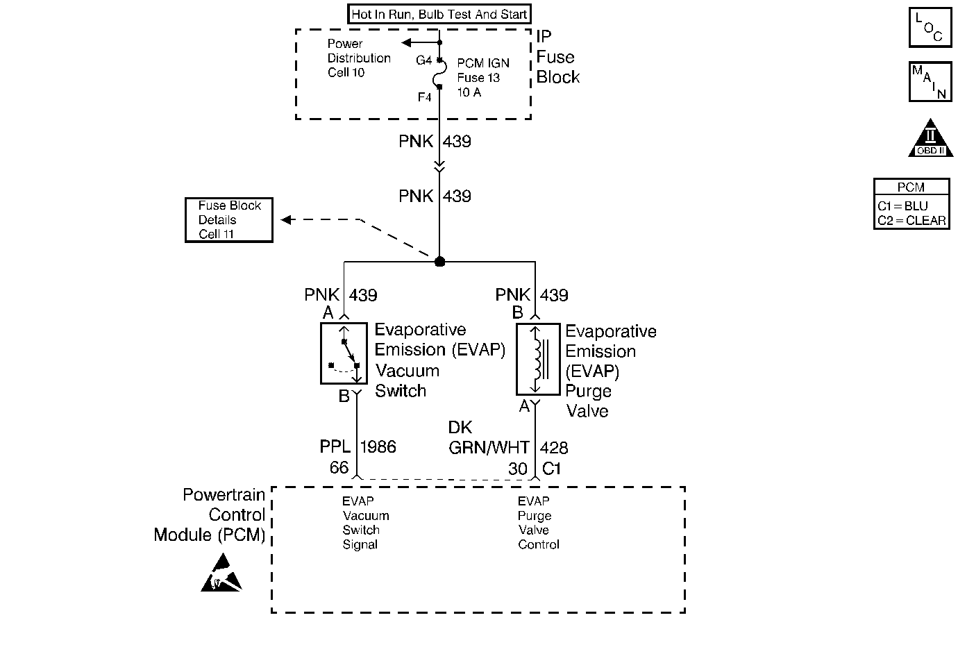
Circuit Description
The EVAP purge valve allows manifold vacuum to purge the canister. The Powertrain Control Module (PCM) supplies a ground to energize the EVAP purge valve (purge ON). The EVAP purge valve control circuit is Pulse Width Modulated (PWM) or turned ON and OFF several times a second. The duty cycle (pulse width) is determined by engine operating conditions including load, throttle position, coolant temperature and ambient temperature. The duty cycle is calculated by the PCM and the output is commanded when the appropriate conditions have been met.
The EVAP purge vacuum switch is a normally closed switch positioned in the purge line between the canister and the EVAP purge valve. The EVAP purge vacuum switch will open when vacuum increases to greater than 5 inches of water in the purge line. The PCM monitors the EVAP purge vacuum switch signal to determine of the evaporative emission control system is working properly. If the switch is closed (no purge flow) when the PCM is commanding the EVAP purge valve ON, DTC P0441 should be set. If the switch is open (purge flow detected) when the PCM is not commanding the EVAP purge valve ON, DTC P1441 should be set. If the switch is open when sufficient vacuum should not be present, DTC P1442 should be set.
Refer to the DTC charts for further diagnostic procedures regarding the EVAP system.
Diagnostic Aids
Check for the following conditions:
| • | Poor connection at PCM. |
| Inspect harness connectors for backed out terminals, improper mating, broken locks, improperly formed or damaged terminals, and poor terminal to wire connection. |
| • | Damaged harness. |
| Inspect the wiring harness for damage. If the harness appears to be OK, observe the EVAP vacuum switch display on the scan tool while moving connectors and wiring harnesses related to the switch. A change in the display will indicate the location of the fault. |
| • | Incorrect vacuum hose routing. |
| Verify that the vacuum hose routing to the canister purge vacuum switch and the canister purge solenoid is correct and that the vacuum hoses to the canister purge solenoid are not switched. |
| - | Refer to Emission Hose Routing Diagram (VIN 1) . |
| - | Refer to Emission Hose Routing Diagram (VIN K) . |
Step | Action | Value(s) | Yes | No | ||||||
|---|---|---|---|---|---|---|---|---|---|---|
1 | Was the Powertrain On-Board Diagnostic (OBD) System Check performed? | -- | ||||||||
2 |
Was a problem found? | -- | System OK | |||||||
3 | Engine idling, observe EVAP Vacuum Sw. while commanding the EVAP purge solenoid OFF with the scan tool. Does EVAP Vacuum Sw. display No Purge with the EVAP purge solenoid commanded OFF? | -- | Go to DTC P1441 Evaporative Emission (EVAP) System Flow During Non-Purge | |||||||
4 | Engine idling, observe EVAP Vacuum Sw. while commanding the EVAP purge solenoid ON with the scan tool. Does EVAP Vacuum Sw. display Purge with the EVAP purge solenoid commanded ON? | -- | System OK | Go to DTC P1441 Evaporative Emission (EVAP) System Flow During Non-Purge |
