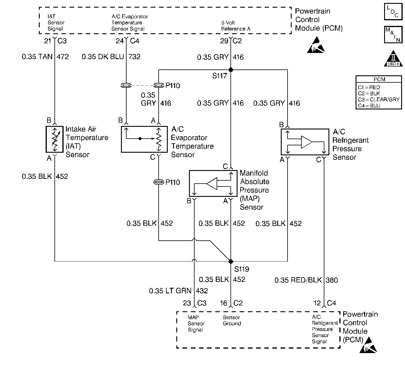
Circuit Description
The Manifold Absolute Pressure (MAP) sensor is mounted to the top of the intake manifold. The MAP sensor measures pressure changes within the intake manifold which are an indication of engine load. The MAP sensor has a 5.0 volt reference circuit, a ground and a signal circuit.
The PCM compares the MAP sensor signal activity with throttle angle and RPM. If the PCM detects a large MAP change without sensing a change in throttle angle and RPM, this DTC will set.
Conditions for Setting the DTC
| • | DTCs P0107, P0108, P0121, P0122 and P0123 not set. |
| • | Engine operating. |
| • | ASR/TCS not in a traction event (If so equipped). |
| • | Engine speed does not change more than 100 RPM. |
| • | TP sensor angle does not change more than 5%. |
| • | EGR position does not change more than 25%. |
| • | IAC position, at a steady state. |
| • | No change (steady state) in A/C clutch, power steering signal, brake signal, and transmission position. |
| • | PCM detects a substantial change in MAP, without being proceeded by a large change in throttle angle and RPM. |
| • | All conditions stable for 0.5 second. |
| • | All conditions met for 4.5 seconds. |
Action Taken When the DTC Sets
| • | The PCM will illuminate the Malfunction Indicator Lamp (MIL) on the second consecutive drive trip that the diagnostic runs and fails. |
| • | The PCM will record operating conditions at the time the diagnostic fails. The first time the diagnostic fails, this information will be stored in Failure Records. If the diagnostic reports a failure on the second consecutive drive trip, the operating conditions at the time of failure will be written to Freeze Frame and the Failure record will be updated. |
| • | The PCM will use TP sensor values to calculate MAP. |
Conditions for Clearing the MIL/DTC
| • | The PCM will turn the MIL OFF after three consecutive drive trips that the diagnostic runs and does not fail. |
| • | A History DTC will clear after forty consecutive warm-up cycles, if no failures are reported by this or any other emission related diagnostic. |
| • | PCM battery voltage is interrupted. |
| • | Using a Scan tool. |
Diagnostic Aids
An intermittent may be caused by the following:
| • | Mis-routed harness. |
| • | Rubbed through wire insulation. |
| • | Broken wire inside the insulation. |
For intermittents, refer to Symptoms .
Test Description
Number(s) below refer to step numbers on the diagnostic table.
-
Erratic engine vacuum caused by a base engine problem or a misfire condition should be diagnosed first.
-
When moving related connectors, visually/physically inspect connectors for the following:
| • | Poor mating of the connector halves or a terminal not fully seated in the connector body (backed out). |
| • | Improperly formed or damaged terminals. All connector terminals in the related circuits should be carefully reformed or replaced to insure proper contact tension. |
| • | Poor terminal to wire connection. Inspect for poor crimps, crimping over wire insulation rather than the wire. |
| • | Dirt or corrosion on terminals. Inspect connector seals for being there and for being damaged. |
Step | Action | Value(s) | Yes | No | ||||||||
|---|---|---|---|---|---|---|---|---|---|---|---|---|
1 | Was the Powertrain On-Board Diagnostic (OBD) System Check performed? | -- | ||||||||||
Is DTC P0300 also set? | -- | |||||||||||
3 |
Is MAP varying more than the specified amount? | 6.3 kPa | ||||||||||
Is the MAP value affected by moving the harness or connectors? | -- | |||||||||||
5 |
Important: This value will vary with altitude. Refer to Test Description. Does the scan tool display the MAP value shown? | 100 kPa | ||||||||||
6 |
Did the MAP value change smoothly through the entire range of the test without any erratic readings? | -- | ||||||||||
7 | Apply 20 inch Hg vacuum to the MAP sensor. Is the MAP sensor reading the same or less than the specified value? | 34 kPa | ||||||||||
8 | Disconnect the vacuum source from the MAP sensor. Does the MAP sensor reading return to its original value? | -- | ||||||||||
9 |
Does the scan tool indicate that this diagnostic failed this ignition? | -- | Go to Diagnostic Aids | |||||||||
10 | Check the MAF sensor harness for incorrect routing. Check for the following conditions:
Was a problem found and corrected? | -- | ||||||||||
11 | Check for a plugged or leaking vacuum supply to the MAP sensor. Was a problem found and corrected? | -- | ||||||||||
12 | Check for the following conditions and repair as necessary:
Is action complete? | -- | ||||||||||
13 | Replace the MAP sensor. Is action complete? | -- | -- | |||||||||
14 | Check the connections at the PCM. Was a problem found and corrected? | -- | ||||||||||
15 |
Important:: Replacement PCM must be programmed. Refer to Powertrain Control Module Replacement/Programming . Replace the PCM. Is the action complete? | -- | -- | |||||||||
16 |
Does the scan tool indicate that this test ran and passed? | -- | ||||||||||
17 | Using the scan tool, select Capture Info, Review Info. Are any DTCs displayed that have not been diagnosed? | -- | Go to the applicable DTC table | System OK |
