Tools Required
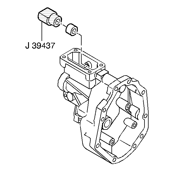
- Install the shift shaft bushing. Use the J 39437
.
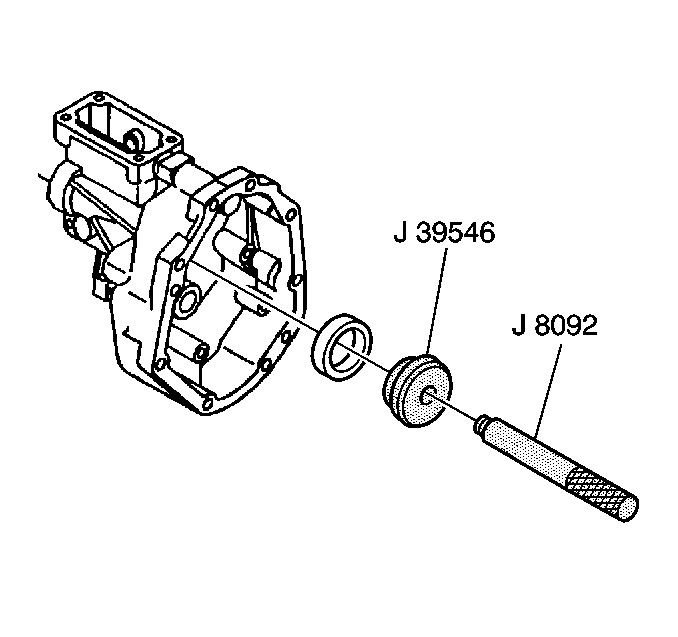
- Install the mainshaft bearing race. Use the J 39546
and the J 8092
.
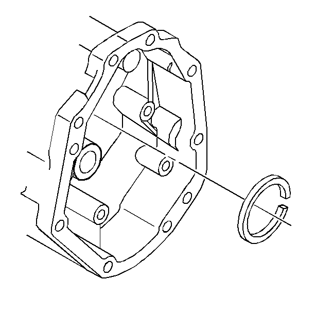
- Install the mainshaft
bearing race retainer ring.
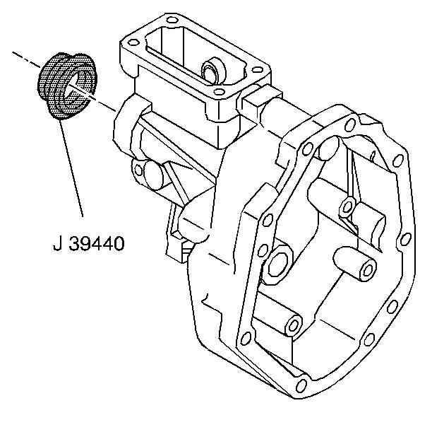
- Install the rear seal and boot (Locate the drain hole in the rear seal and
boot down). Use the J 39440
.
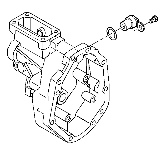
- Install the following parts:
| 5.1. | The O-ring seal to the vehicle speed sensor |
| 5.2. | The vehicle speed sensor and the clamp |
| 5.3. | The vehicle speed sensor bolt |
Tighten
The bolt to 10 N·m (89 Ib in).
Notice: Use the correct fastener in the correct location. Replacement fasteners
must be the correct part number for that application. Fasteners requiring
replacement or fasteners requiring the use of thread locking compound or sealant
are identified in the service procedure. Do not use paints, lubricants, or
corrosion inhibitors on fasteners or fastener joint surfaces unless specified.
These coatings affect fastener torque and joint clamping force and may damage
the fastener. Use the correct tightening sequence and specifications when
installing fasteners in order to avoid damage to parts and systems.
Caution: The reverse lockout assembly is under spring pressure. Exercise caution
when removing the retainer ring, as bodily injury may result.
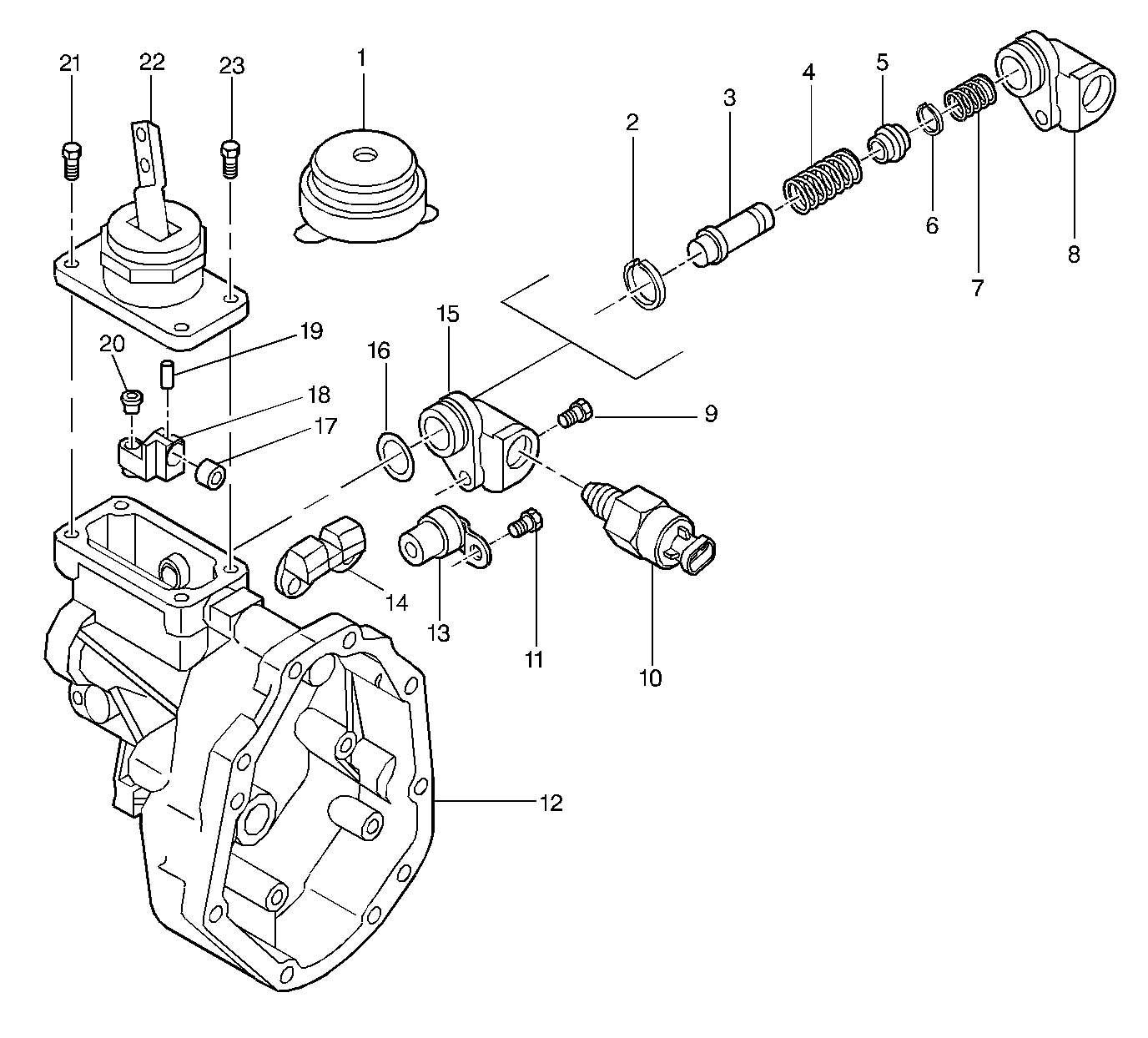
- Assemble the reverse lockout assembly in the following sequence:
| 6.1. | Refer to
Extension Housing (1 of 2)
|
| 6.2. | Install the reverse lockout plunger (3). |
| 6.3. | Install the reverse lockout outer spring (4). |
| 6.4. | Install the reverse lockout collar (5). |
| 6.5. | Compress the reverse lockout plunger (3) and the collar (5) in
a vise and Install the retainer ring (6). |
| 6.6. | Install the reverse lockout inner spring (7). |
| 6.7. | Install the reverse lockout components in the body (8). |
| 6.8. | Install the retainer ring (2). |
| 6.9. | Install the O-ring (16) to body (8). |
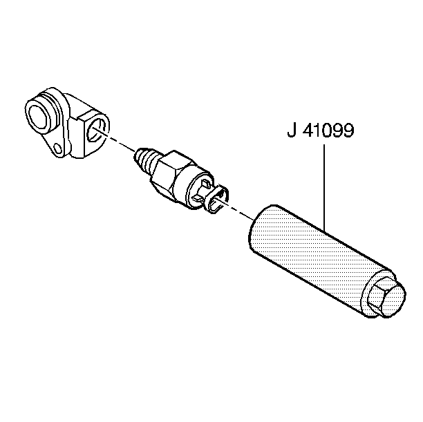
- Install the reverse lockout solenoid to reverse lockout body assembly. Use
the J 41099
.
Tighten
The solenoid to 40 N·m (30 Ib ft).
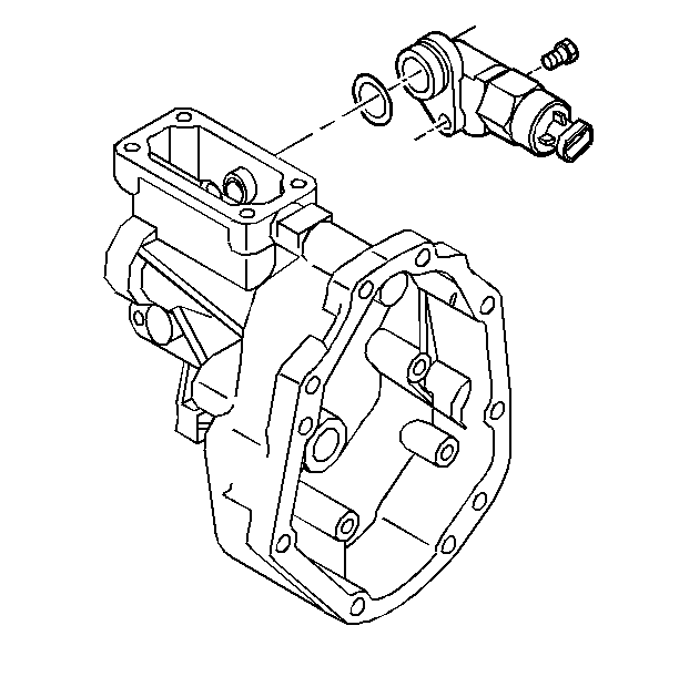
- Install the following parts:
| 8.1. | The reverse lockout assembly |
| 8.2. | The reverse lockout assembly bolt |
Tighten
The bolt to 18 N·m (13 Ib in).
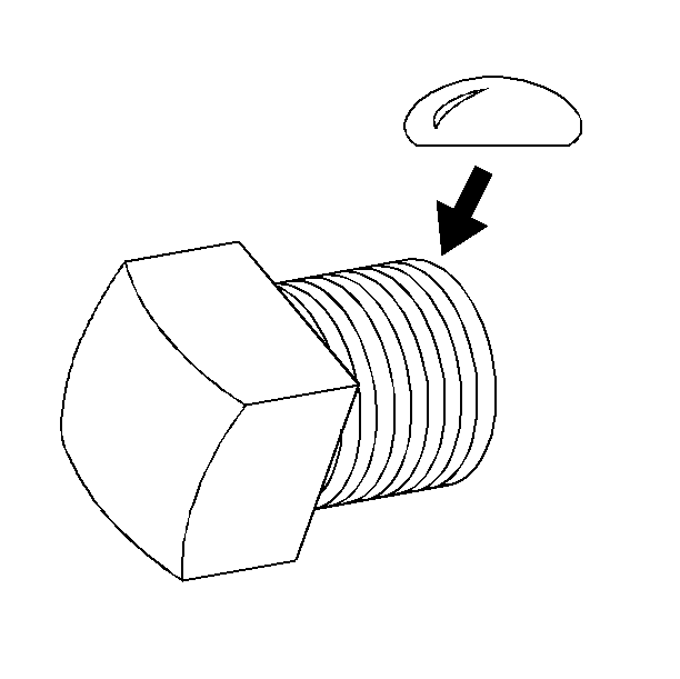
- Apply thread sealer to the transmission lubricant drain plug. Use GM P/N 1052080.
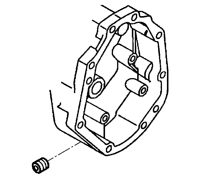
- Install the transmission lubricant drain plug.
Tighten
The plug to 18 N·m (13 Ib ft).
Tools Required
| • | J 42198 Transmission
Rear Seal Installer |
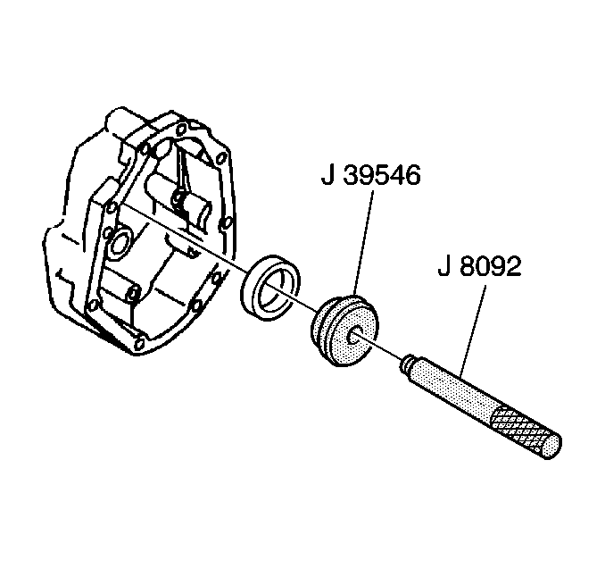
- Install the mainshaft bearing race. Use
the J 39546
and the J 8092
.

- Install the mainshaft bearing race retainer
ring.
Notice: Failure to install the inner output shaft seal correctly will cause
a leak.
- Install the inner output shaft seal with garter spring facing inward, usingJ 26508-A
.
Notice: Failure to install the outer output shaft seal correctly will cause
a leak.
- Install the outer output shaft seal with garter spring facing outward, usingJ 42198
.
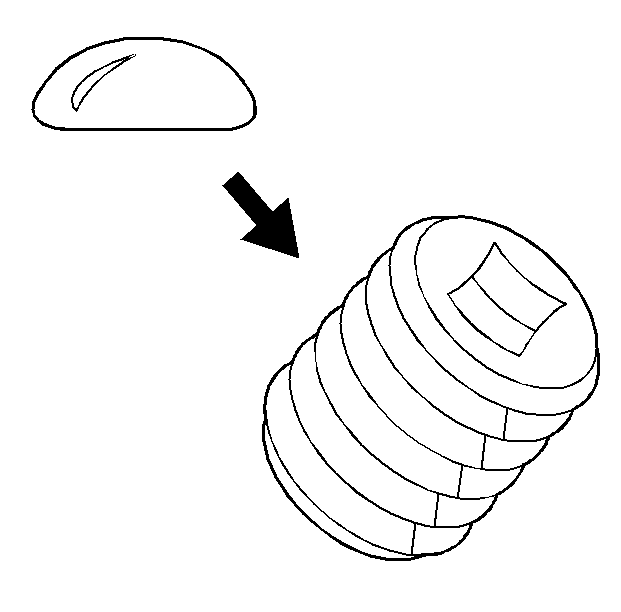
- Apply thread sealer GM P/N United
States 12346004, GM P/N Canada 10953480 to
the transmission case drain plug.

Notice: Use the correct fastener in the correct location. Replacement fasteners
must be the correct part number for that application. Fasteners requiring
replacement or fasteners requiring the use of thread locking compound or sealant
are identified in the service procedure. Do not use paints, lubricants, or
corrosion inhibitors on fasteners or fastener joint surfaces unless specified.
These coatings affect fastener torque and joint clamping force and may damage
the fastener. Use the correct tightening sequence and specifications when
installing fasteners in order to avoid damage to parts and systems.
- Install the transmission case drain plug.
Tighten
Tighten the plug to 18 N·m (13 Ib ft).


