Cylinder Head Replacement Left
Removal Procedure
- Drain the coolant. Refer to Cooling System Draining and Filling in Engine Cooling.
- Remove the lower intake manifold. Refer to Intake Manifold Replacement .
- Remove the left exhaust manifold. Refer to Exhaust Manifold Replacement .
- Remove the valve rocker arms and pushrods. Refer to Valve Rocker Arm and Push Rod Replacement .
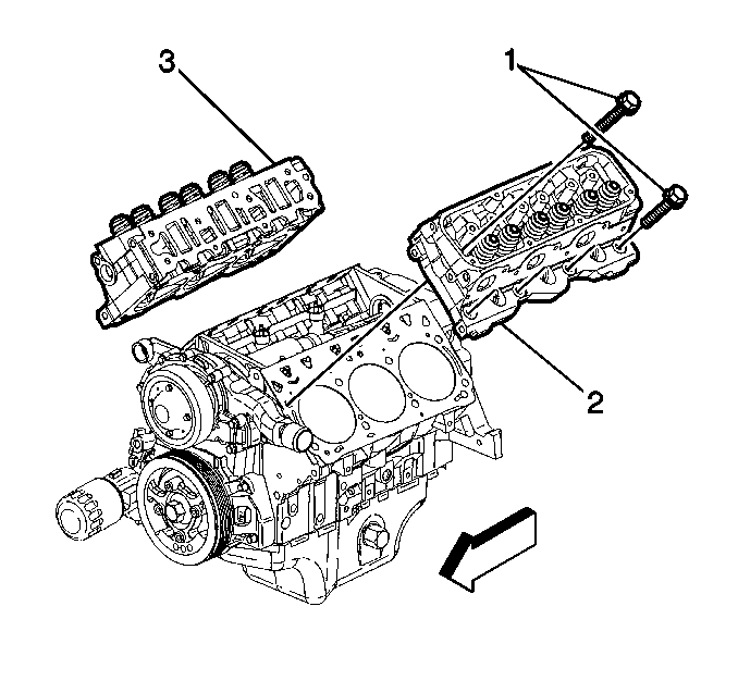
- Remove the cylinder head bolts (1).
- Remove the left cylinder head (2).
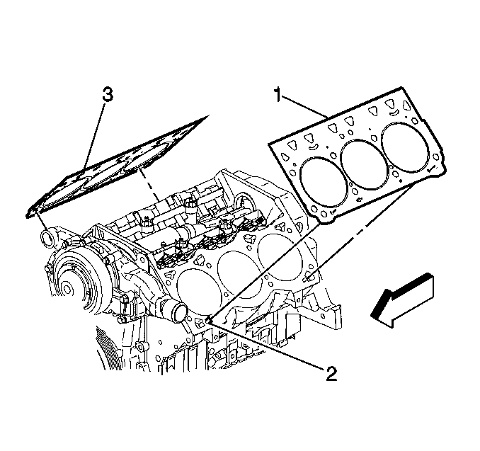
- Remove the left cylinder head gasket (1).
- Clean and inspect the cylinder head. Refer to Cylinder Head Cleaning and Inspection .
Installation Procedure
Tools Required
J 36660-A Torque Angle Meter
- Install a new left cylinder head gasket (1) to the alignment pins (2).
- Install the left cylinder head (2).
- Install the cylinder head bolts (1).
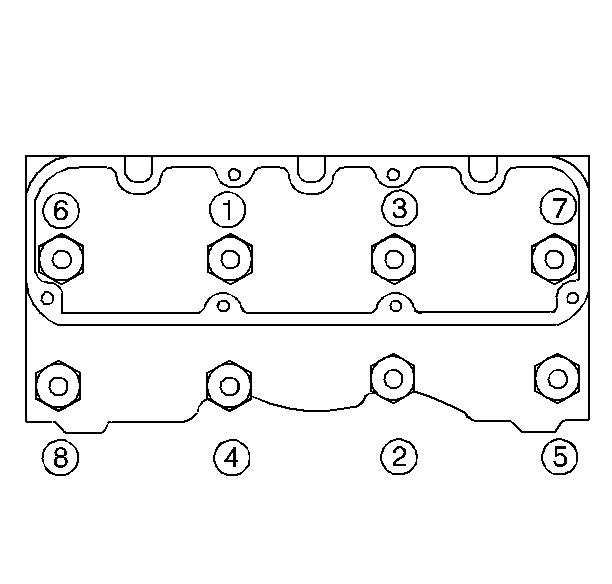
- Tighten the cylinder head bolts following the given sequence.
- Install the valve rocker arms and pushrods. Refer to Valve Rocker Arm and Push Rod Replacement .
- Install the left exhaust manifold. Refer to Exhaust Manifold Replacement .
- Install the lower intake manifold. Refer to Intake Manifold Replacement
- Refill the engine coolant. Refer to Cooling System Draining and Filling in Engine Cooling.
- Change the engine oil and filter. Refer to Engine Oil and Oil Filter Replacement .
Important: The arrow on the gasket must point to the front of the engine. Failure to install the gasket properly will cause gasket failure and possible engine failure.
Notice: This bolt is designed to permanently stretch when tightened, and therefore MUST be replaced anytime it is removed. The correct part number fastener must be used to replace this type of fastener. Do not use a bolt that is stronger in this application. If the correct bolt is not used, the parts will not be tightened correctly. The system or the components may be damaged.
Notice: Use the correct fastener in the correct location. Replacement fasteners must be the correct part number for that application. Fasteners requiring replacement or fasteners requiring the use of thread locking compound or sealant are identified in the service procedure. Do not use paints, lubricants, or corrosion inhibitors on fasteners or fastener joint surfaces unless specified. These coatings affect fastener torque and joint clamping force and may damage the fastener. Use the correct tightening sequence and specifications when installing fasteners in order to avoid damage to parts and systems.
Tighten
Tighten the cylinder head bolts to 50 N·m (37 lb ft)
in sequence. Using J 36660-A
tighten the cylinder head bolts an additional 120 degrees.
Cylinder Head Replacement Right
Removal Procedure
- Drain the coolant. Refer to Cooling System Draining and Filling in Engine Cooling.
- Remove the lower intake manifold. Refer to Intake Manifold Replacement .
- Remove the right exhaust manifold. Refer to Exhaust Manifold Replacement .
- Remove the valve rocker arms and the pushrods. Refer to Valve Rocker Arm and Push Rod Replacement
- Remove the cylinder head bolts (1).
- Remove the right cylinder head (3).
- Remove the right cylinder head gasket (3).
- Clean and inspect the cylinder head. Refer to Cylinder Head Cleaning and Inspection .
Installation Procedure
Tools Required
J 36660-A Torque Angle Meter
- Install a new right cylinder head gasket (3) to the alignment pins (2).
- Install the right cylinder head (3).
- Install the cylinder head bolts (1).
- Tighten the cylinder head bolts following the given sequence.
- Install the pushrods and the valve rocker arms. Refer to Valve Rocker Arm and Push Rod Replacement .
- Install the right exhaust manifold. Refer to Exhaust Manifold Replacement .
- Install the lower intake manifold. Refer to Intake Manifold Replacement .
- Refill the engine coolant. Refer to Cooling System Draining and Filling in Engine Cooling.
- Change the engine oil and filter. Refer to Engine Oil and Oil Filter Replacement .
Important: The arrow on the gasket must point to the front of the engine. Failure to install the gasket properly will cause gasket failure and possible engine damage.
Notice: This bolt is designed to permanently stretch when tightened, and therefore MUST be replaced anytime it is removed. The correct part number fastener must be used to replace this type of fastener. Do not use a bolt that is stronger in this application. If the correct bolt is not used, the parts will not be tightened correctly. The system or the components may be damaged.
Notice: Use the correct fastener in the correct location. Replacement fasteners must be the correct part number for that application. Fasteners requiring replacement or fasteners requiring the use of thread locking compound or sealant are identified in the service procedure. Do not use paints, lubricants, or corrosion inhibitors on fasteners or fastener joint surfaces unless specified. These coatings affect fastener torque and joint clamping force and may damage the fastener. Use the correct tightening sequence and specifications when installing fasteners in order to avoid damage to parts and systems.
Tighten
Tighten the cylinder head bolts to 50 N·m (37 lb ft)
in sequence. Using J 36660-A
tighten the cylinder head bolts an additional 120 degrees.
