GM Service Manual Online
For 1990-2009 cars only

3.8L Engine Control Schematics
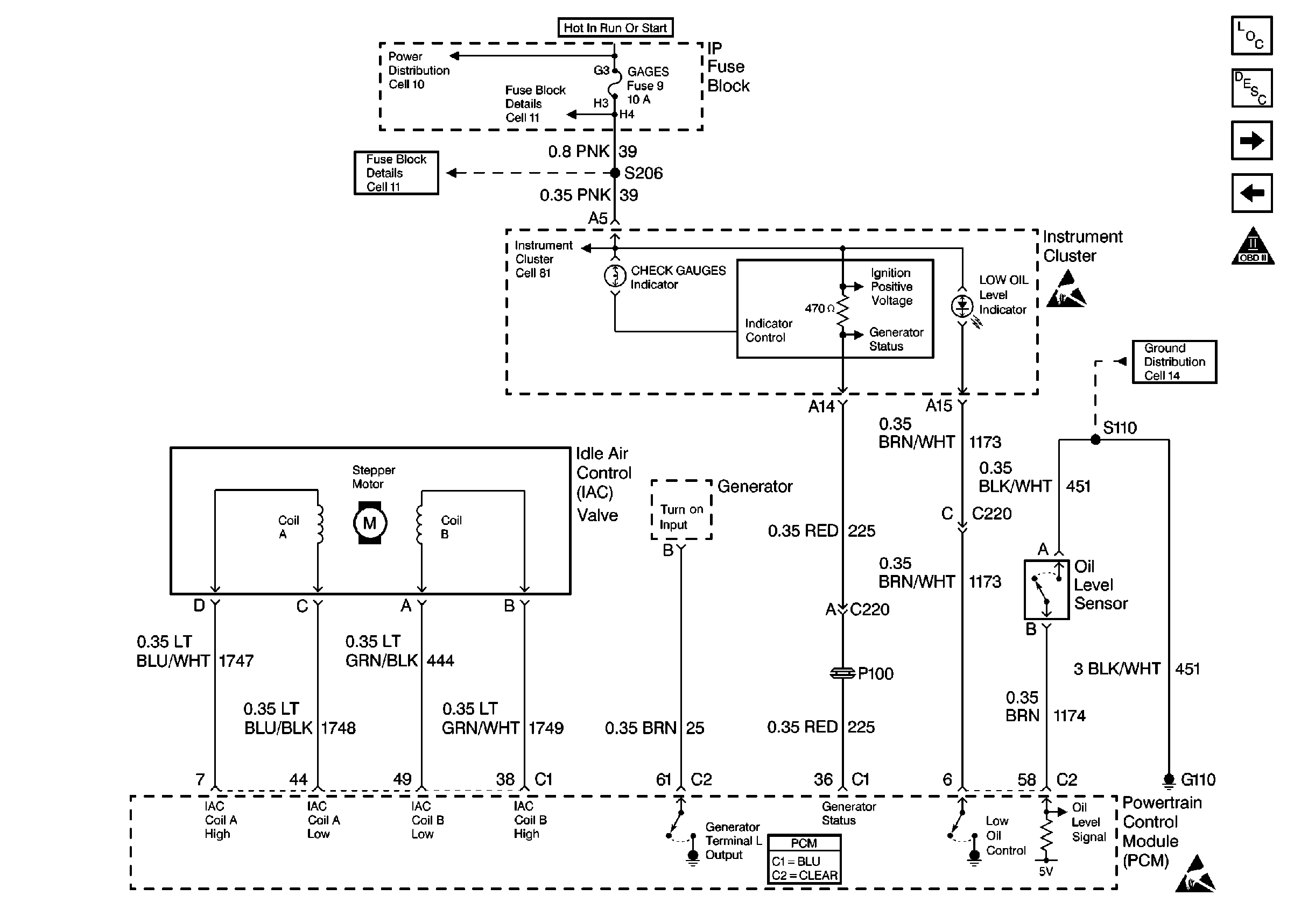
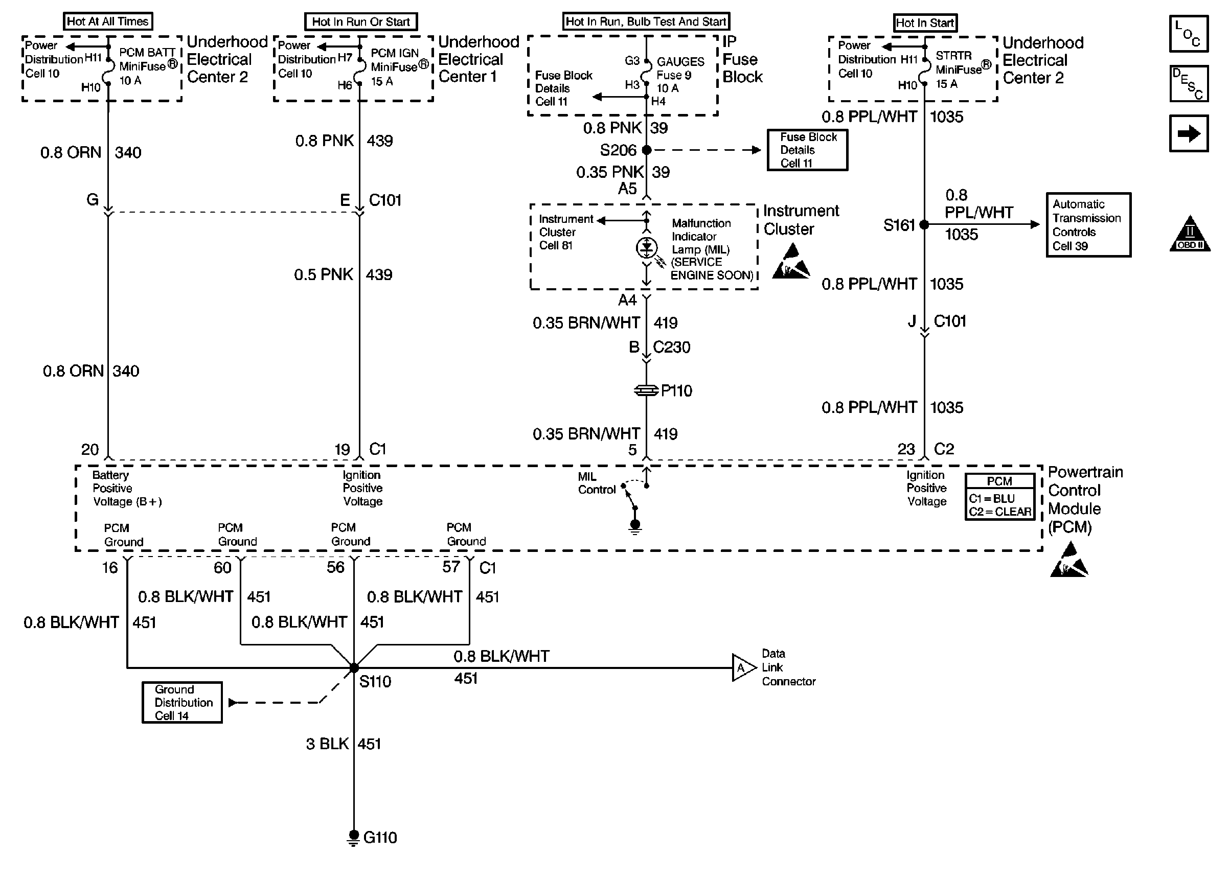
Figure 1:

Power, Ground and MIL


Object Number: 192064  Size: FS
Engine Controls Components
Malfunction Indicator Lamp (MIL) Inoperative
Power, Ground and MIL
OBD II Symbol Description Notice
Powertrain Control Module Connector End Views
Handling ESD Sensitive Parts Notice
Power Distribution Schematics
Fuse Block Schematics
Ground Distribution Schematics
Automatic Transmission Controls Schematics
Instrument Cluster: Analog Schematics
Power, Ground and MIL
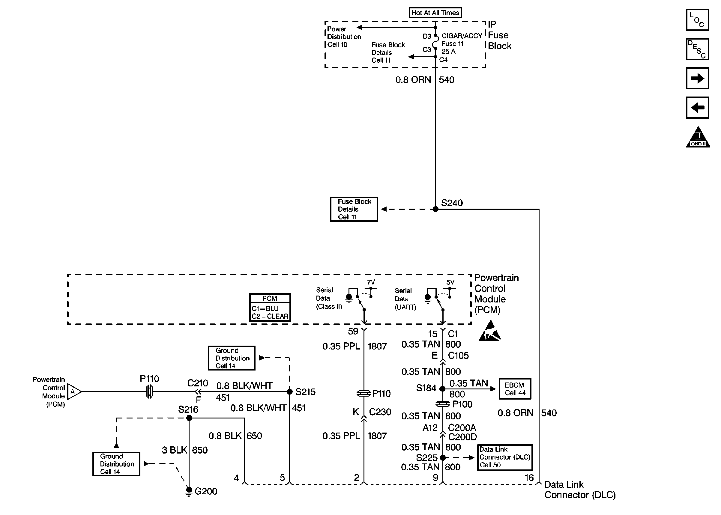
Figure 2:

Power, Ground and MIL


Object Number: 192070  Size: FS
Engine Controls Components
Data Link Connector Diagnosis
Ignition Control, Knock Sensors
Power, Ground and MIL
OBD II Symbol Description Notice
Powertrain Control Module Connector End Views
Handling ESD Sensitive Parts Notice
Power, Ground and MIL
Power Distribution Schematics
Fuse Block Schematics
Ground Distribution Schematics
ABS/TCS Schematics
Data Link Connector Schematics
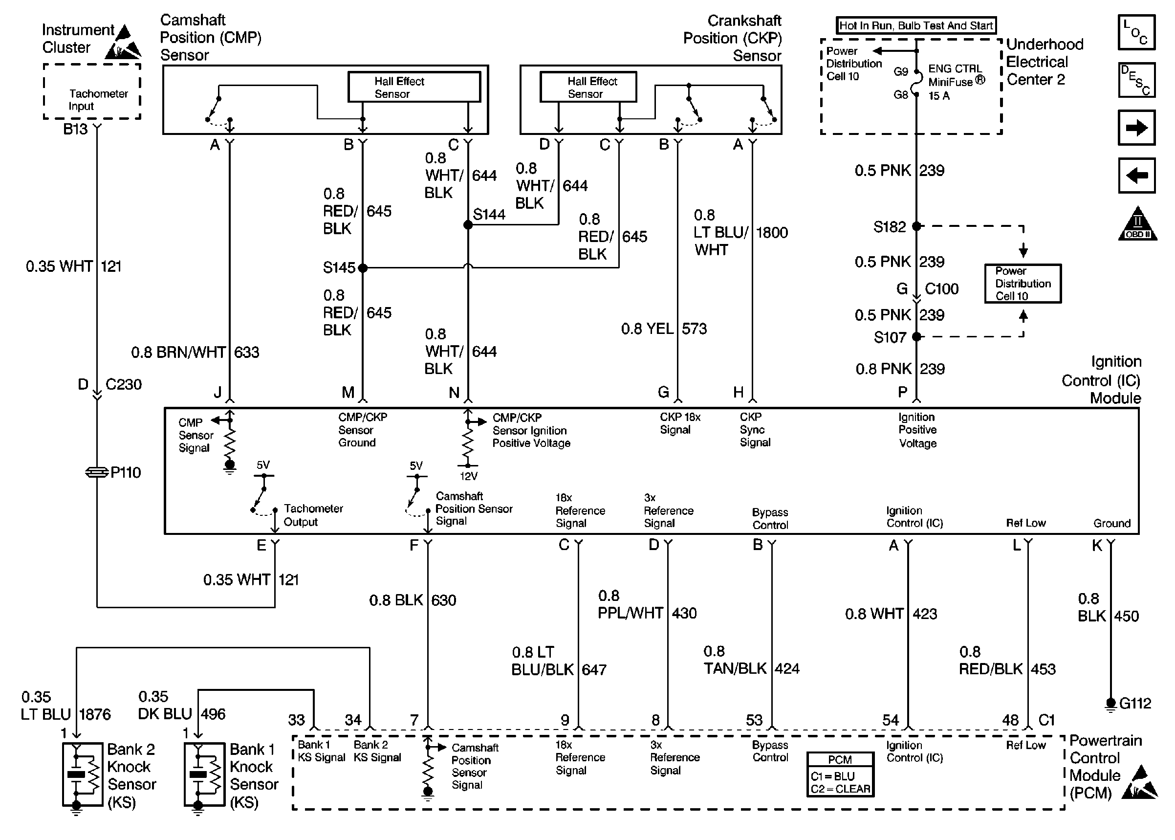
Figure 3:

Ignition Control, Knock Sensors


Object Number: 192078  Size: FS
Engine Controls Components
Engine Cranks but Does Not Run
Fuel Pump Controls
Power, Ground and MIL
OBD II Symbol Description Notice
Handling ESD Sensitive Parts Notice
Powertrain Control Module Connector End Views
Handling ESD Sensitive Parts Notice
Power Distribution Schematics
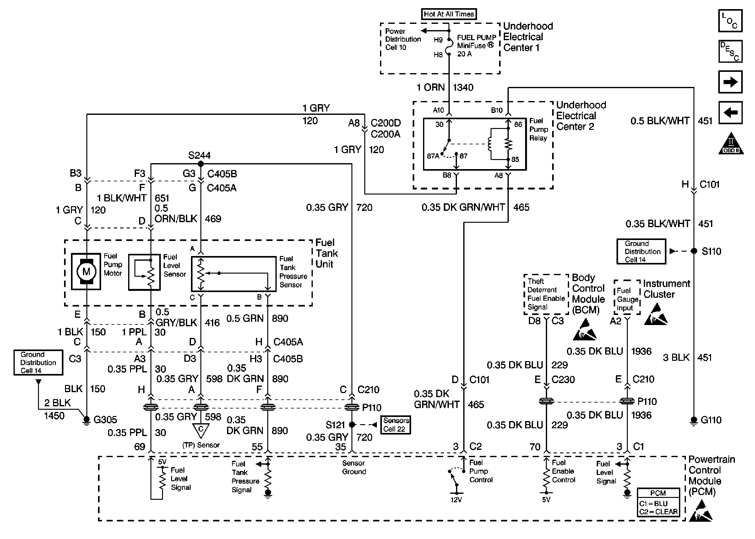
Figure 4:

Fuel Pump Controls


Object Number: 192086  Size: FS
Engine Controls Components
Fuel Pump Electrical Circuit Diagnosis
Fuel Injectors
Ignition Control, Knock Sensors
Power, Ground and MIL
Engine Controls Schematic Icons
Power Distribution Schematics
Ground Distribution Schematics
TP, MAP, ECT, IAT Sensors
Engine Controls Components
Fuel Injectors
Ignition Control, Knock Sensors
OBD II Symbol Description Notice
Handling ESD Sensitive Parts Notice
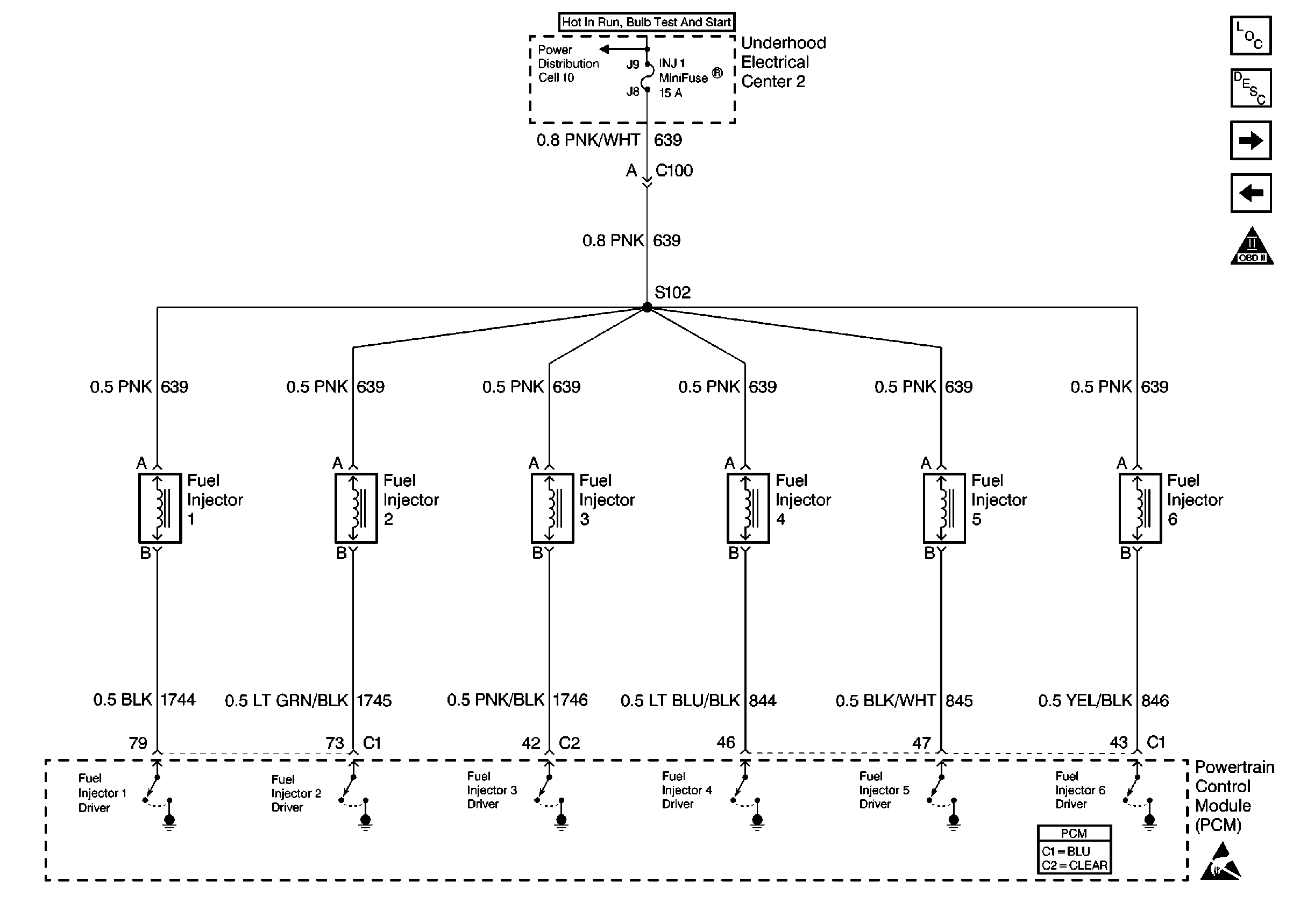
Figure 5:

Fuel Injectors


Object Number: 192091  Size: FS
Engine Controls Components
Engine Cranks but Does Not Run
TP, MAP, ECT, IAT Sensors
Fuel Pump Controls
OBD II Symbol Description Notice
Handling ESD Sensitive Parts Notice
Powertrain Control Module Connector End Views
Power Distribution Schematics
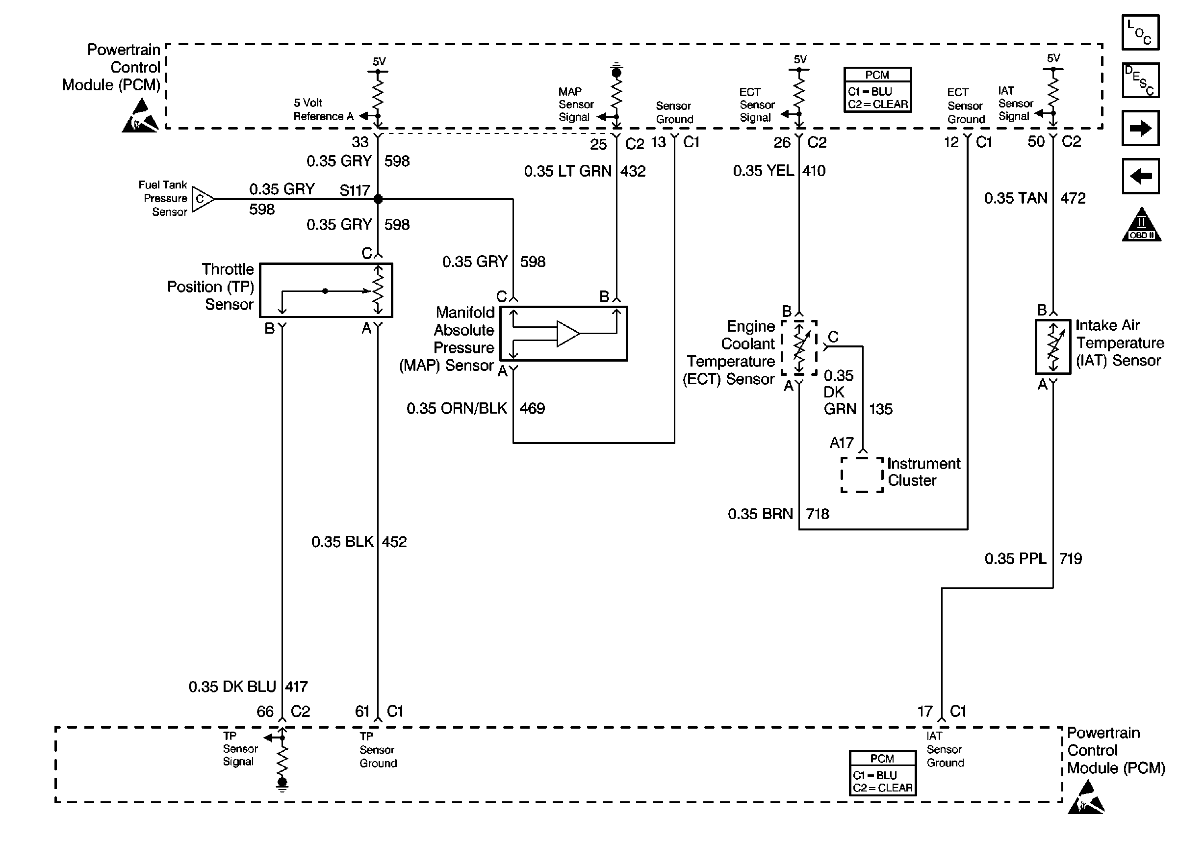
Figure 6:

TP, MAP, ECT, IAT Sensors


Object Number: 192097  Size: FS
Engine Controls Components
Powertrain Control Module Description
HO2S Sensors
Fuel Injectors
OBD II Symbol Description Notice
Handling ESD Sensitive Parts Notice
Powertrain Control Module Connector End Views
Handling ESD Sensitive Parts Notice
Fuel Pump Controls
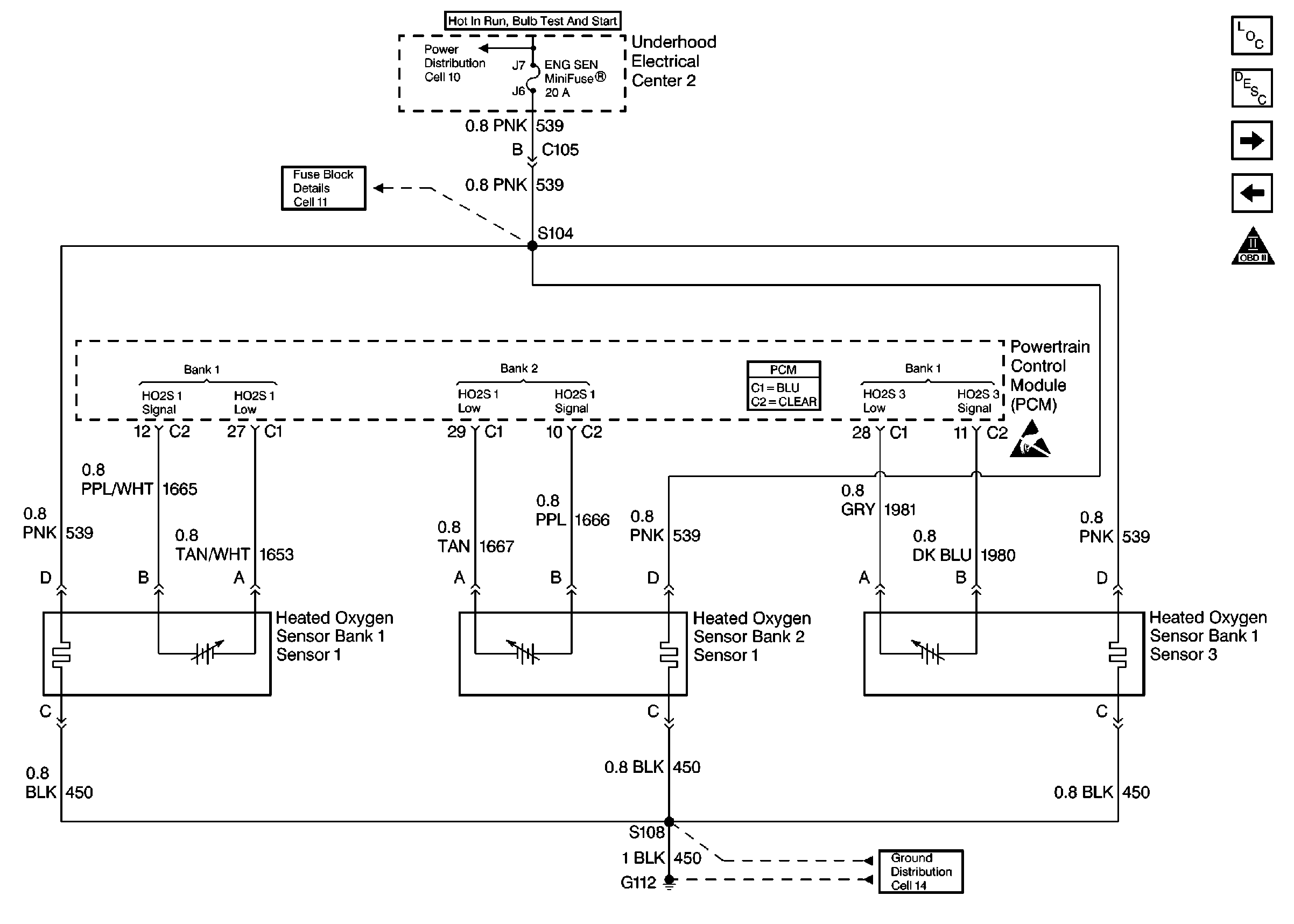
Figure 7:

HO2S Sensors


Object Number: 192099  Size: FS
Engine Controls Components
Information Sensors/Switches Description
MAF Sensor, EVAP System, EGR Valve
TP, MAP, ECT, IAT Sensors
OBD II Symbol Description Notice
Powertrain Control Module Connector End Views
Handling ESD Sensitive Parts Notice
Power Distribution Schematics
Fuse Block Schematics
Ground Distribution Schematics
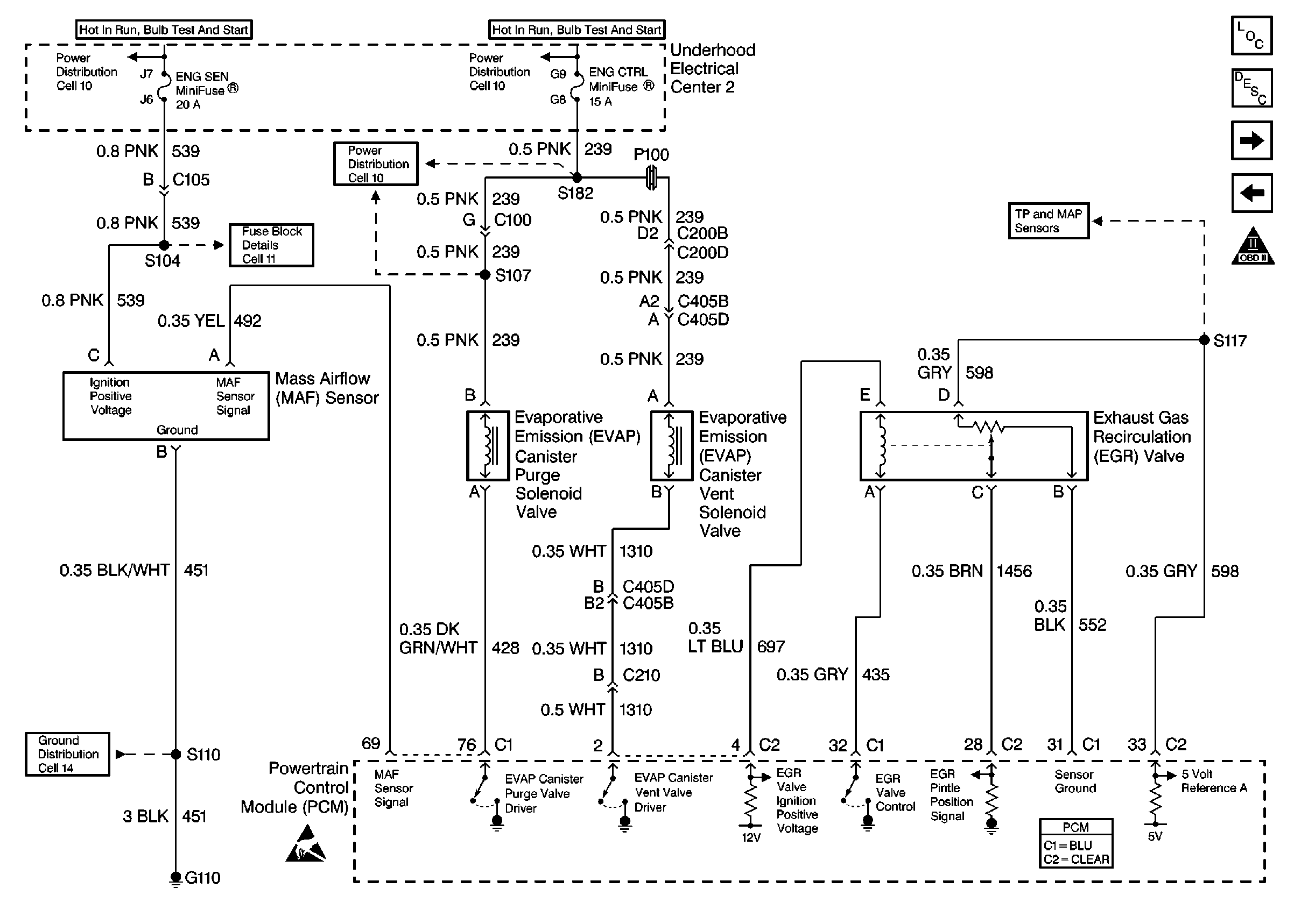
Figure 8:

MAF Sensor, EVAP System, EGR Valve


Object Number: 192107  Size: FS
Engine Controls Components
Evaporative Emission Control System Operation Description
Gen Control, IAC, Check Gauges Lamp
HO2S Sensors
OBD II Symbol Description Notice
Handling ESD Sensitive Parts Notice
Powertrain Control Module Connector End Views
Power Distribution Schematics
Fuse Block Schematics
Ground Distribution Schematics
TP, MAP, ECT, IAT Sensors
Figure 9:

Gen Control, IAC, Check Gauges Lamp


Object Number: 192111  Size: FS
Engine Controls Components
Powertrain Control Module Description
Cruise Control, VSS
MAF Sensor, EVAP System, EGR Valve
OBD II Symbol Description Notice
Handling ESD Sensitive Parts Notice
Powertrain Control Module Connector End Views
Power Distribution Schematics
Fuse Block Schematics
Ground Distribution Schematics
Fuse Block Schematics
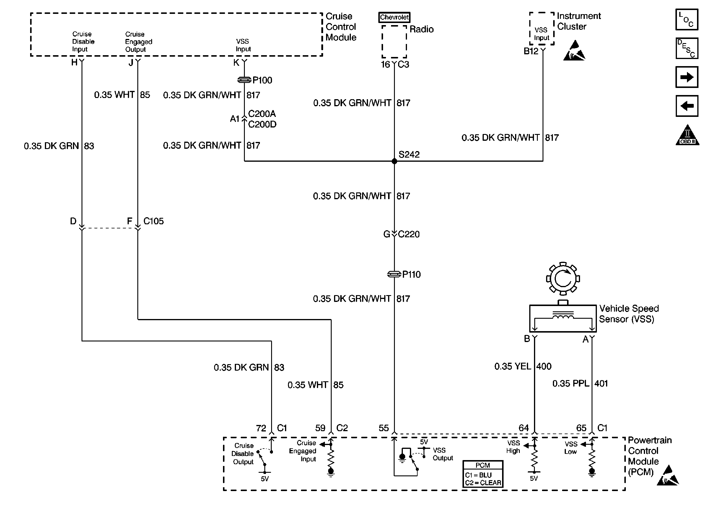
Figure 10:

Cruise Control, VSS


Object Number: 192113  Size: FS
Engine Controls Components
Powertrain Control Module Description
2nd Gear, Clutch Anticipated Switch
Gen Control, IAC, Check Gauges Lamp
OBD II Symbol Description Notice
Handling ESD Sensitive Parts Notice
Powertrain Control Module Connector End Views
Handling ESD Sensitive Parts Notice
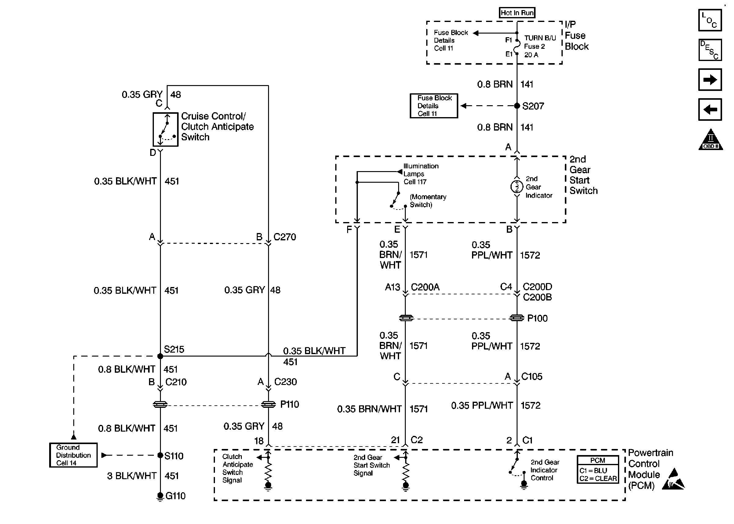
Figure 11:

2nd Gear, Clutch Anticipated Switch


Object Number: 192116  Size: FS
Engine Controls Components
Electronic Component Description
Brake Switch, TCC Solenoid
Cruise Control, VSS
OBD II Symbol Description Notice
Powertrain Control Module Connector End Views
Handling ESD Sensitive Parts Notice
Fuse Block Schematics
Ground Distribution Schematics
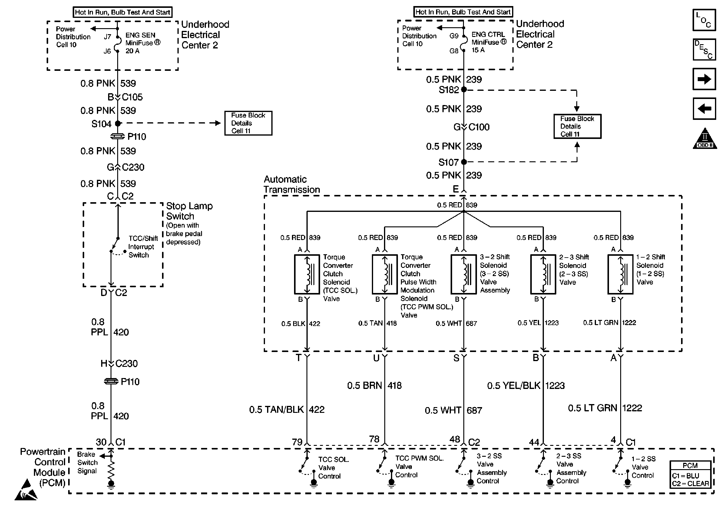
Figure 12:

Brake Switch, TCC Solenoid


Object Number: 193106  Size: FS
Engine Controls Components
Electronic Component Description
Trans Range
2nd Gear, Clutch Anticipated Switch
OBD II Symbol Description Notice
Handling ESD Sensitive Parts Notice
Powertrain Control Module Connector End Views
Power Distribution Schematics
Fuse Block Schematics
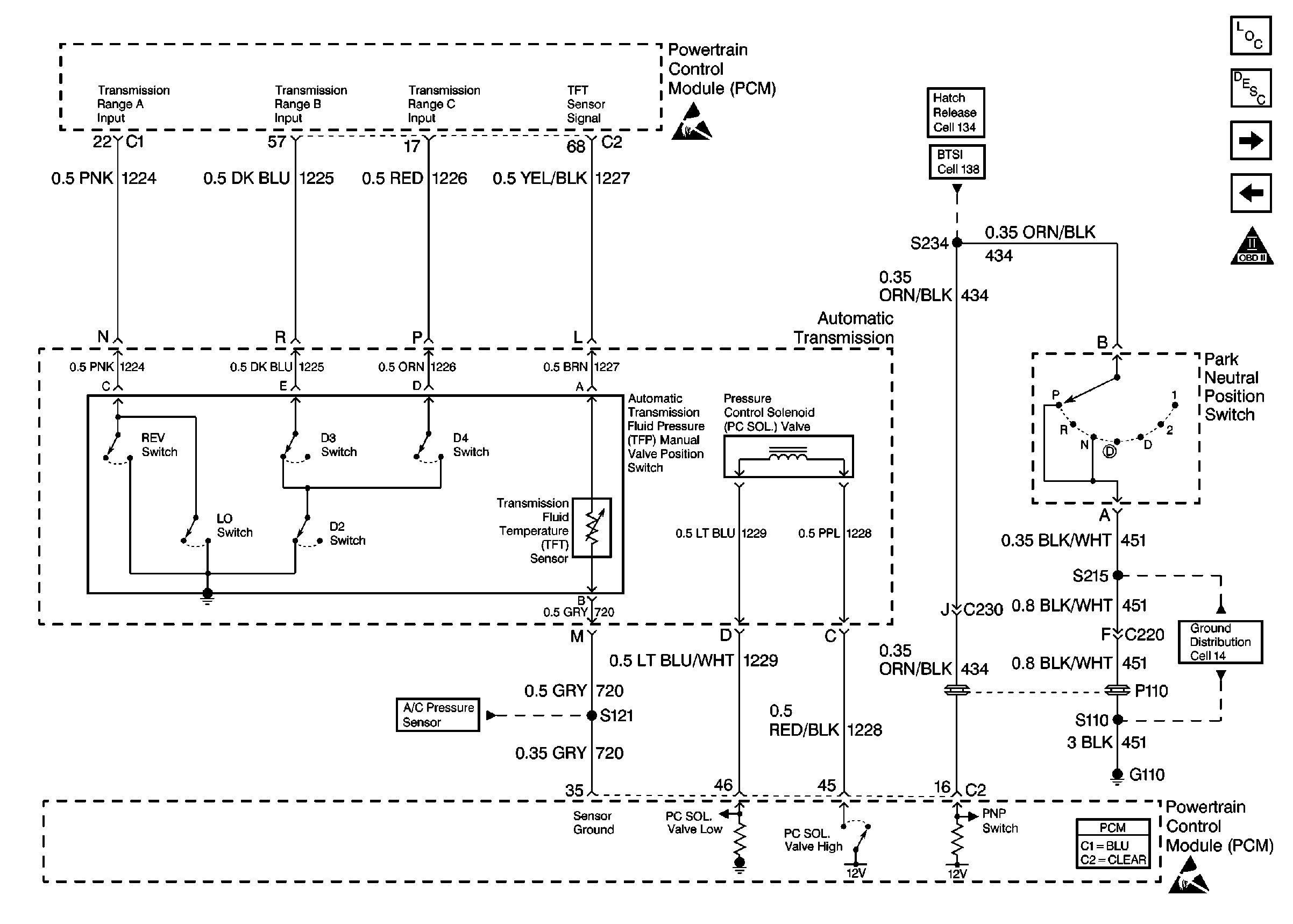
Figure 13:

Trans Range


Object Number: 192118  Size: FS
Engine Controls Components
Electronic Component Description
A/C HVAC Control
Brake Switch, TCC Solenoid
Handling ESD Sensitive Parts Notice
Powertrain Control Module Connector End Views
Handling ESD Sensitive Parts Notice
Ground Distribution Schematics
Shift Lock Control Schematics
Release Systems Schematics
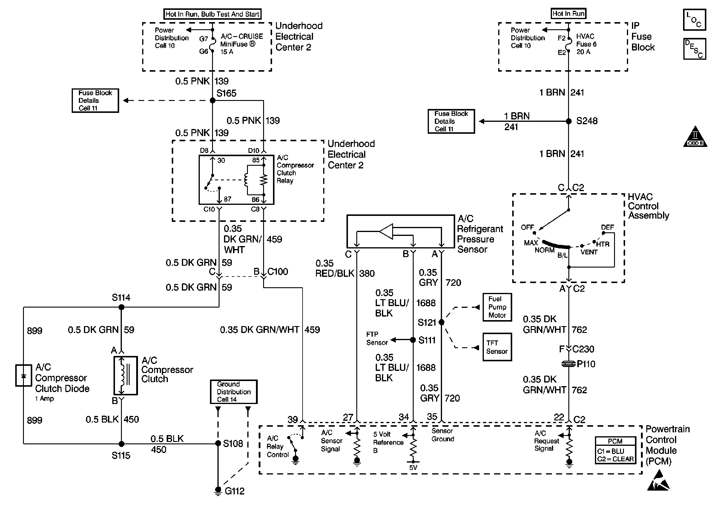
Figure 14:

A/C HVAC Control


Object Number: 192127  Size: FS
Engine Controls Components
Powertrain Control Module Controlled Air Conditioning Description
Cooling Fans
Trans Range
OBD II Symbol Description Notice
Powertrain Control Module Connector End Views
Handling ESD Sensitive Parts Notice
Power Distribution Schematics
Fuse Block Schematics
Ground Distribution Schematics
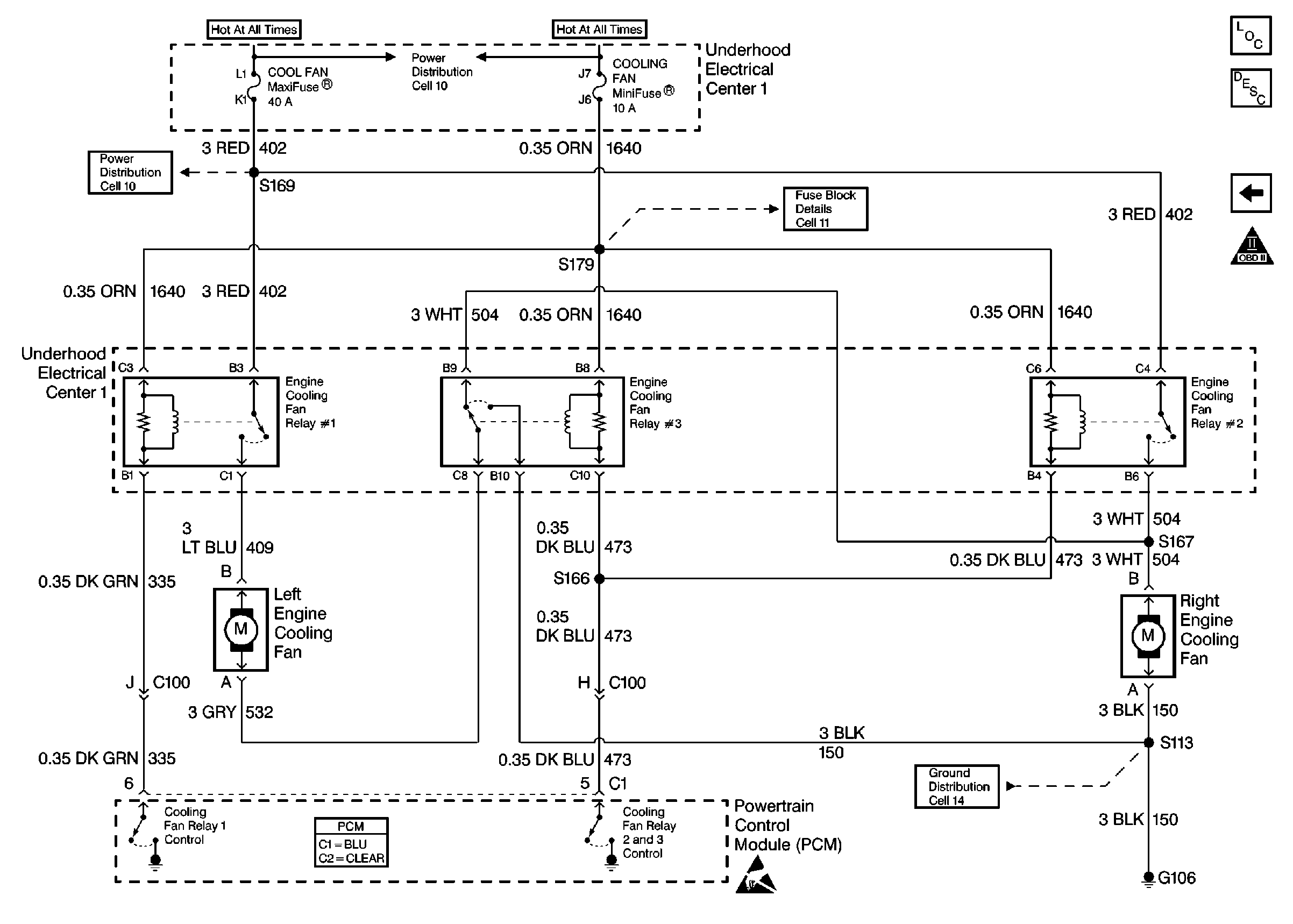
Figure 15:

Cooling Fans


Object Number: 192128  Size: FS
Engine Controls Components
Engine Cooling Fan Description - Electric
A/C HVAC Control
OBD II Symbol Description Notice
Handling ESD Sensitive Parts Notice
Powertrain Control Module Connector End Views
Power Distribution Schematics
Fuse Block Schematics
Ground Distribution Schematics