For 1990-2009 cars only
| Figure 1: |
Power, Ground and MIL
|
| Figure 2: |
Data Link Connector (DLC)
|
| Figure 3: |
Bank 1 Ignition Coil/Modules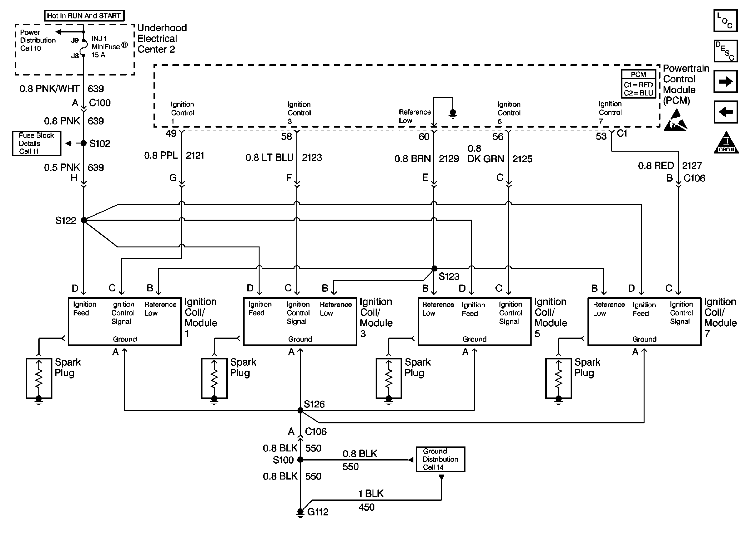
|
| Figure 4: |
Bank 2 Ignition Coil/Modules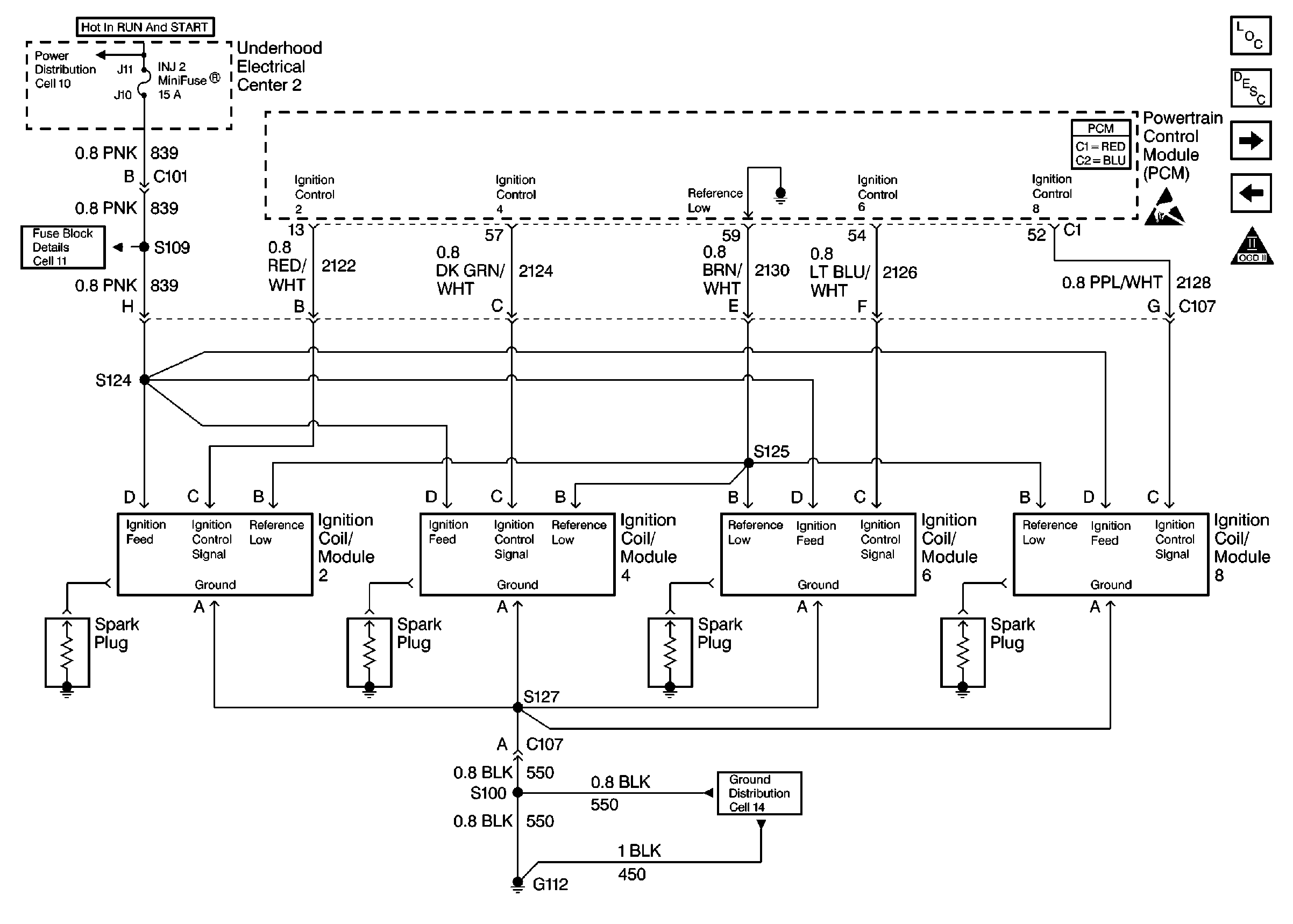
|
| Figure 5: |
Engine Speed Output, CKP and CMP Sensors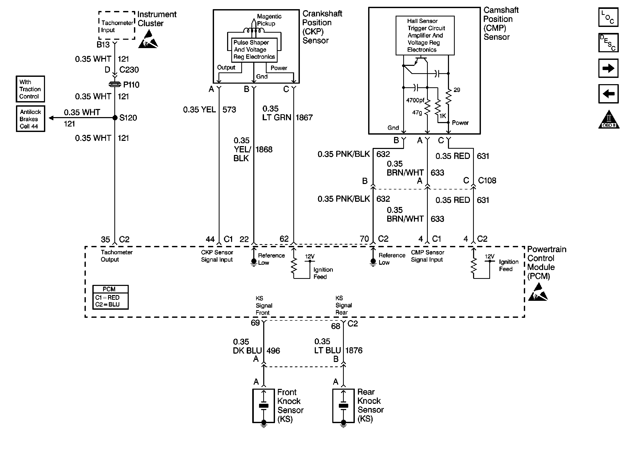
|
| Figure 6: |
Fuel System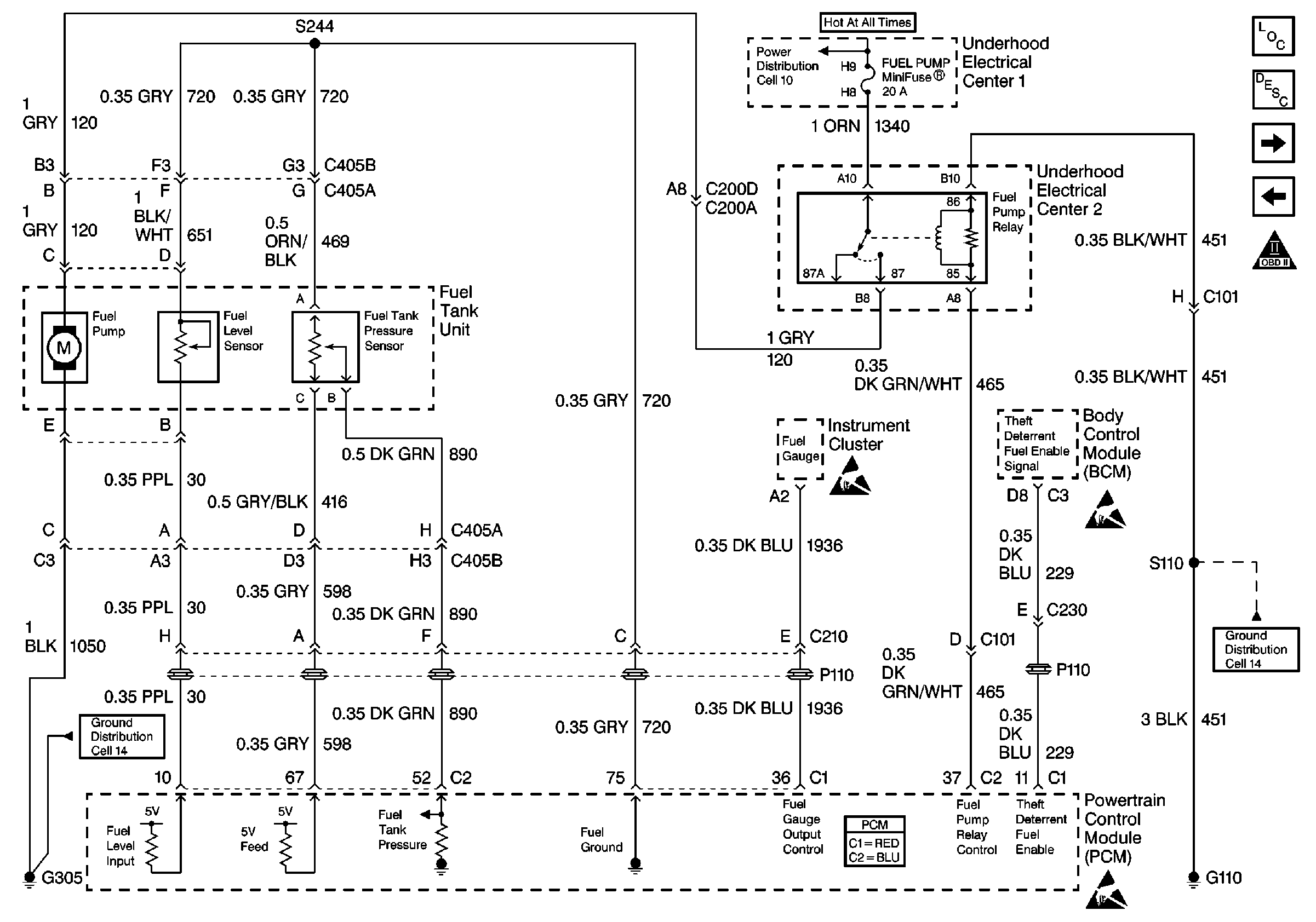
|
| Figure 7: |
Injector Circuits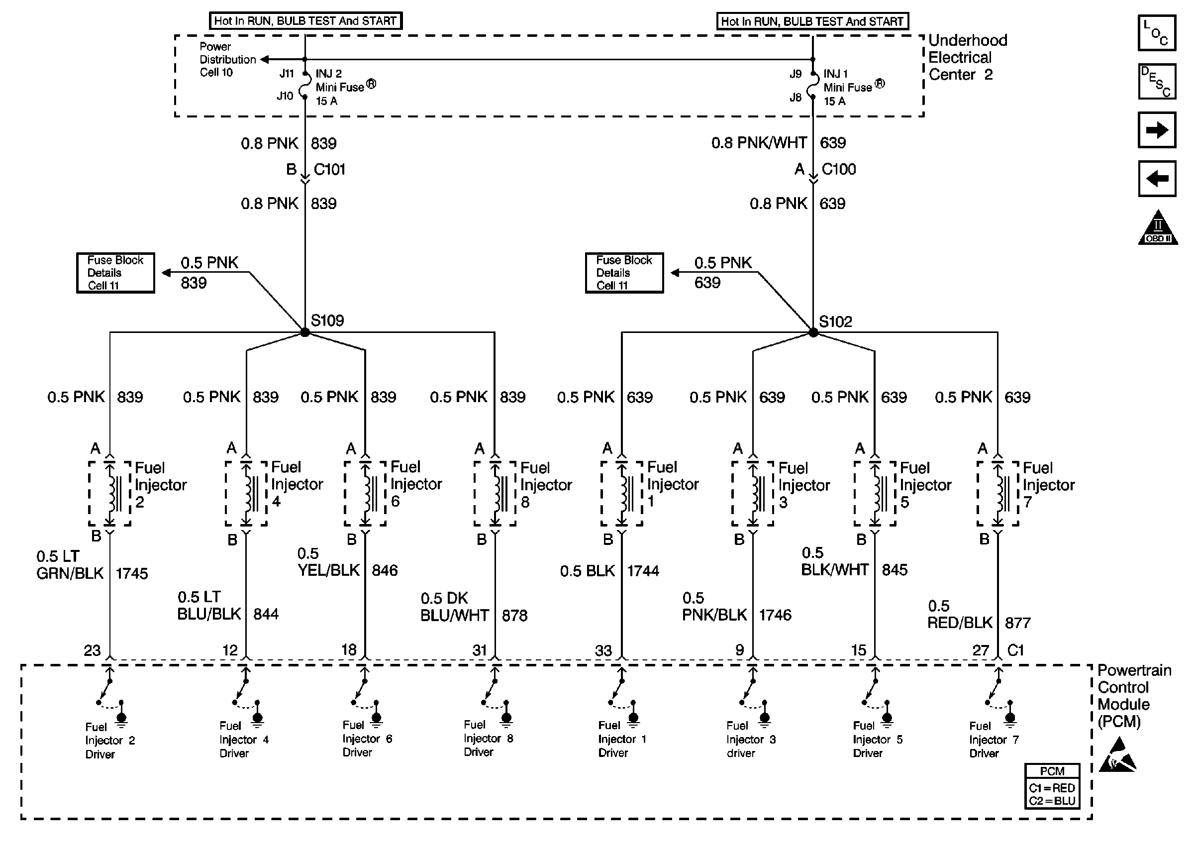
|
| Figure 8: |
Information Sensors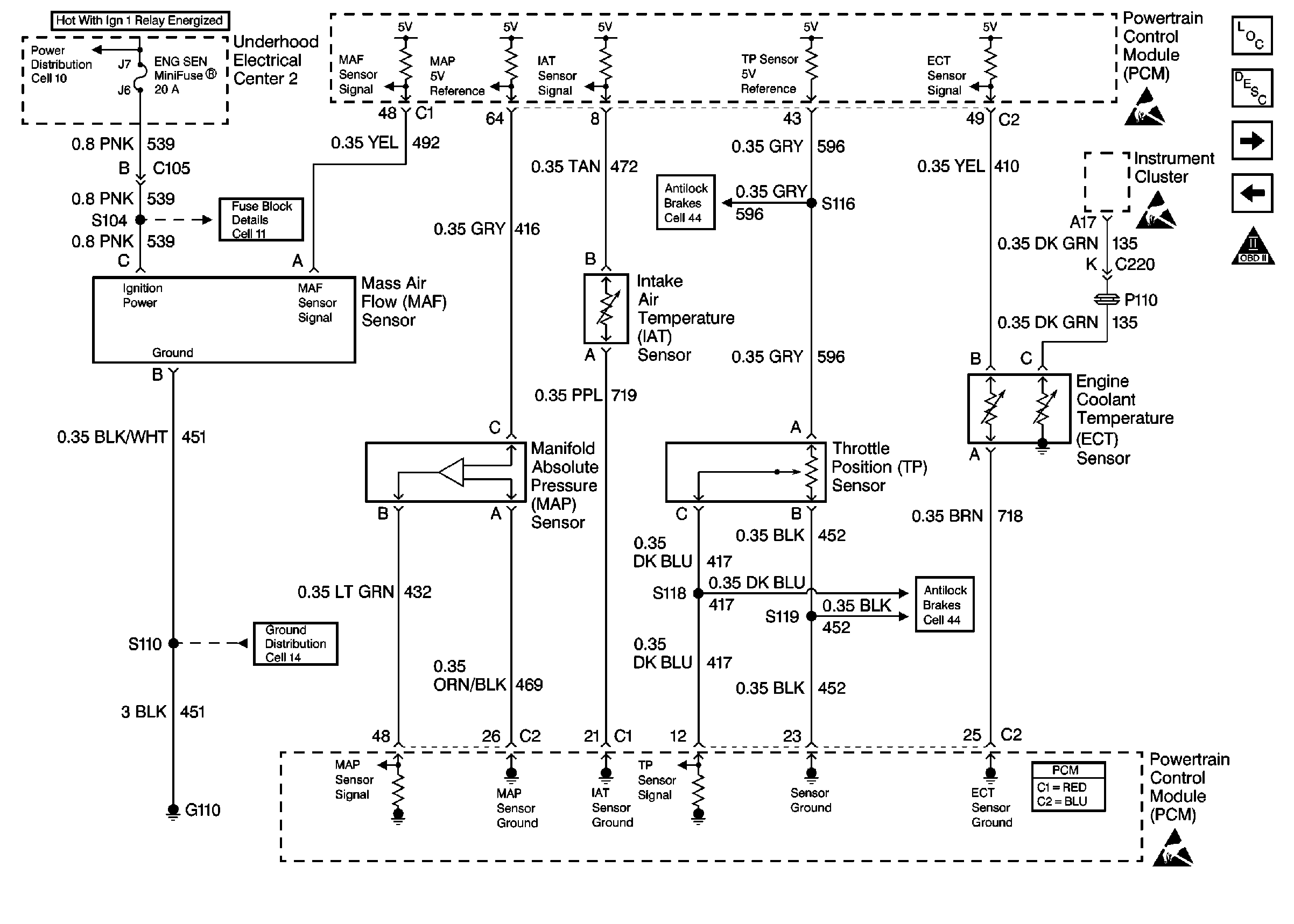
|
| Figure 9: |
Heated Oxygen Sensors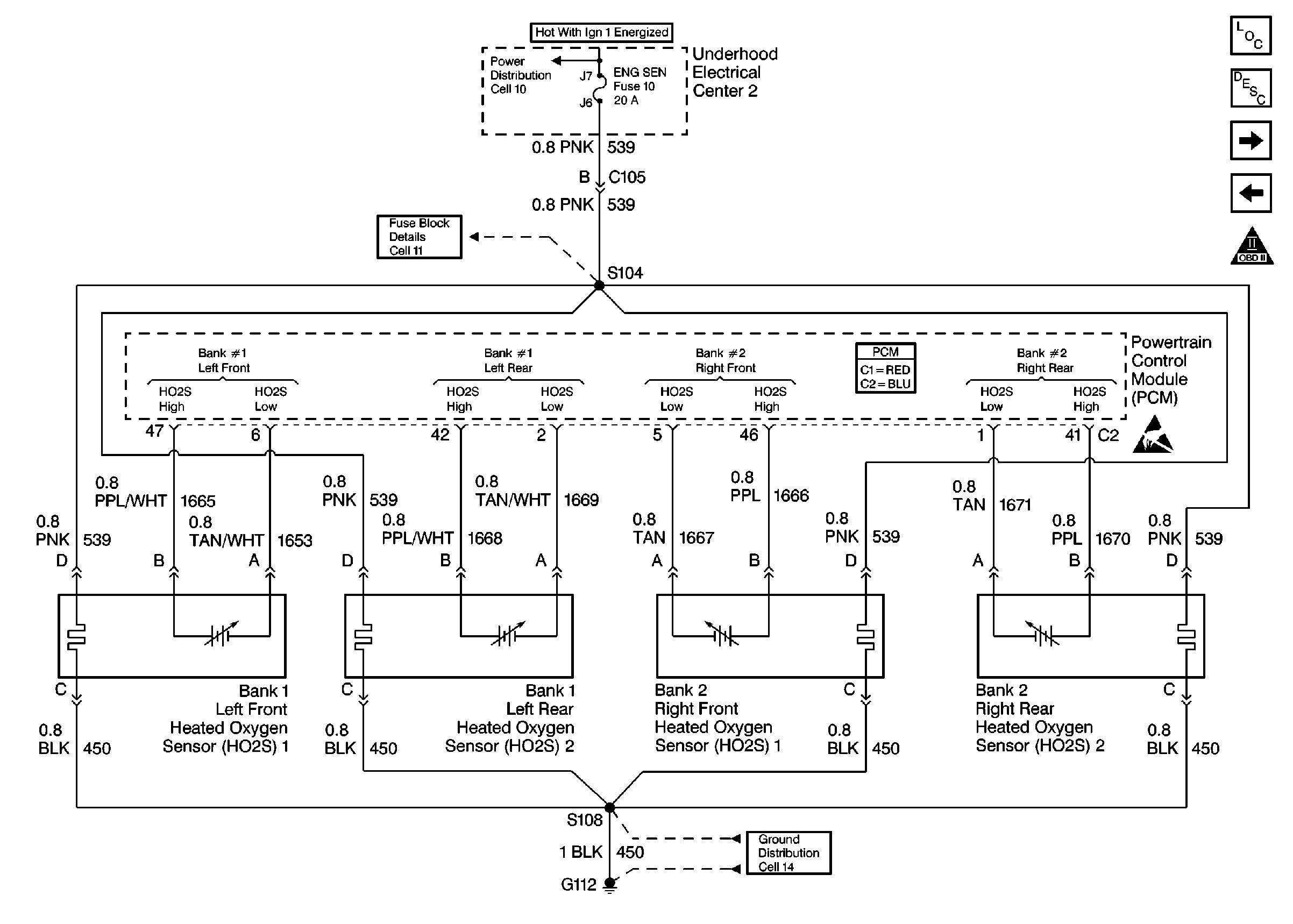
|
| Figure 10: |
AIR and IAC
|
| Figure 11: |
TCS Retard Signal, VSS Output and VSS Signal
|
| Figure 12: |
EVAP and EGR
|
| Figure 13: |
Oil Level
|
| Figure 14: |
Reverse Inhibit and Skip Shift Solenoids
|
| Figure 15: |
Transmission
|
| Figure 16: |
Transmission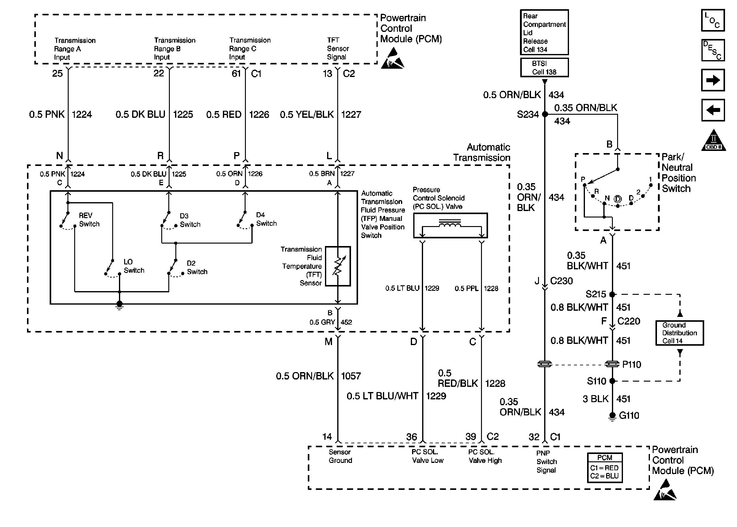
|
| Figure 17: |
A/C System
|
| Figure 18: |
Engine Cooling Fan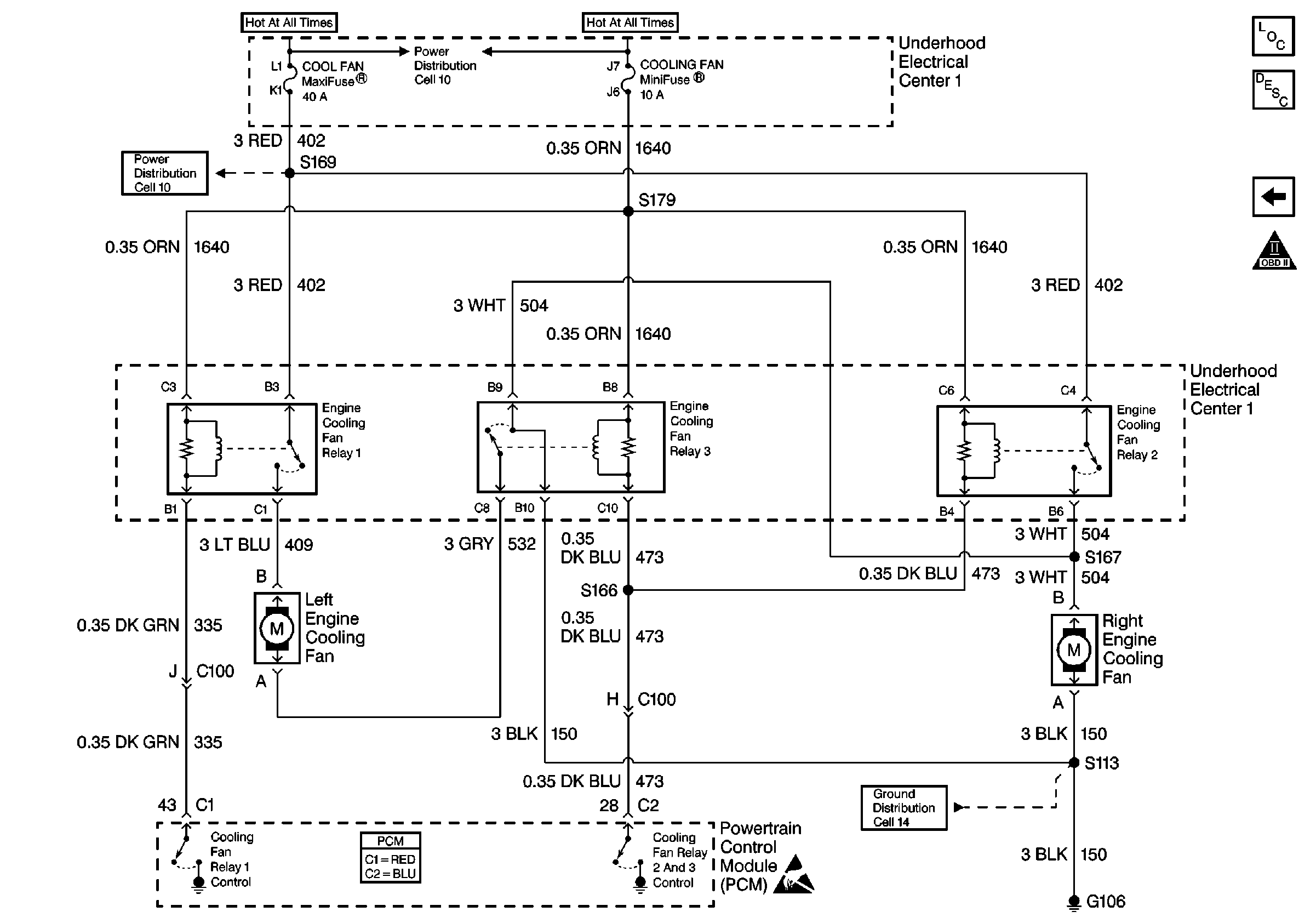
|
