For 1990-2009 cars only
Tools Required
J 29803-A ISO Flaring Kit
Important: Do not use ISO flares for the rear brake pipe connections to the rear wheel cylinders.
- Obtain the recommended tubing and steel fitting nuts of the correct size. Use the outside diameter of the tubing in order to specify the size.
- Cut the tubing to length. Determine the correct length by using string in order to measure the old brake pipe. Add 3 mm (0.125 in) for each ISO flare.
- Cut the end square.
- Chamfer the inside and outside diameter of the tubing. Use a de-burring tool.
- Remove all traces of lubricant from the tubing.
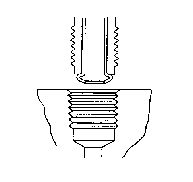
- ISO flare the tubing ends. Use the J 29803-A .
- Install the fittings on the tubing.
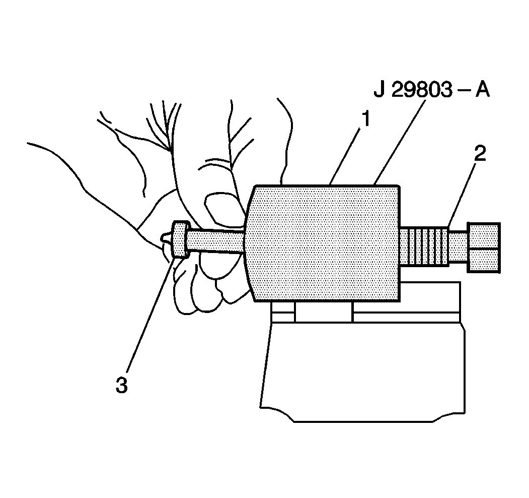
- Clamp the flaring tool body (1) in a vise.
- Select the correct size collet and forming mandrel (3) for the tube size used.
- Insert the proper forming mandrel (3) into the tool body (1).
- Hold the mandrel (3) in place with your finger.
- Thread in the forcing screw (2) until the screw makes contact and begins to move the forming mandrel (3).
- When contact is made, turn back the forcing screw (2) one complete turn.
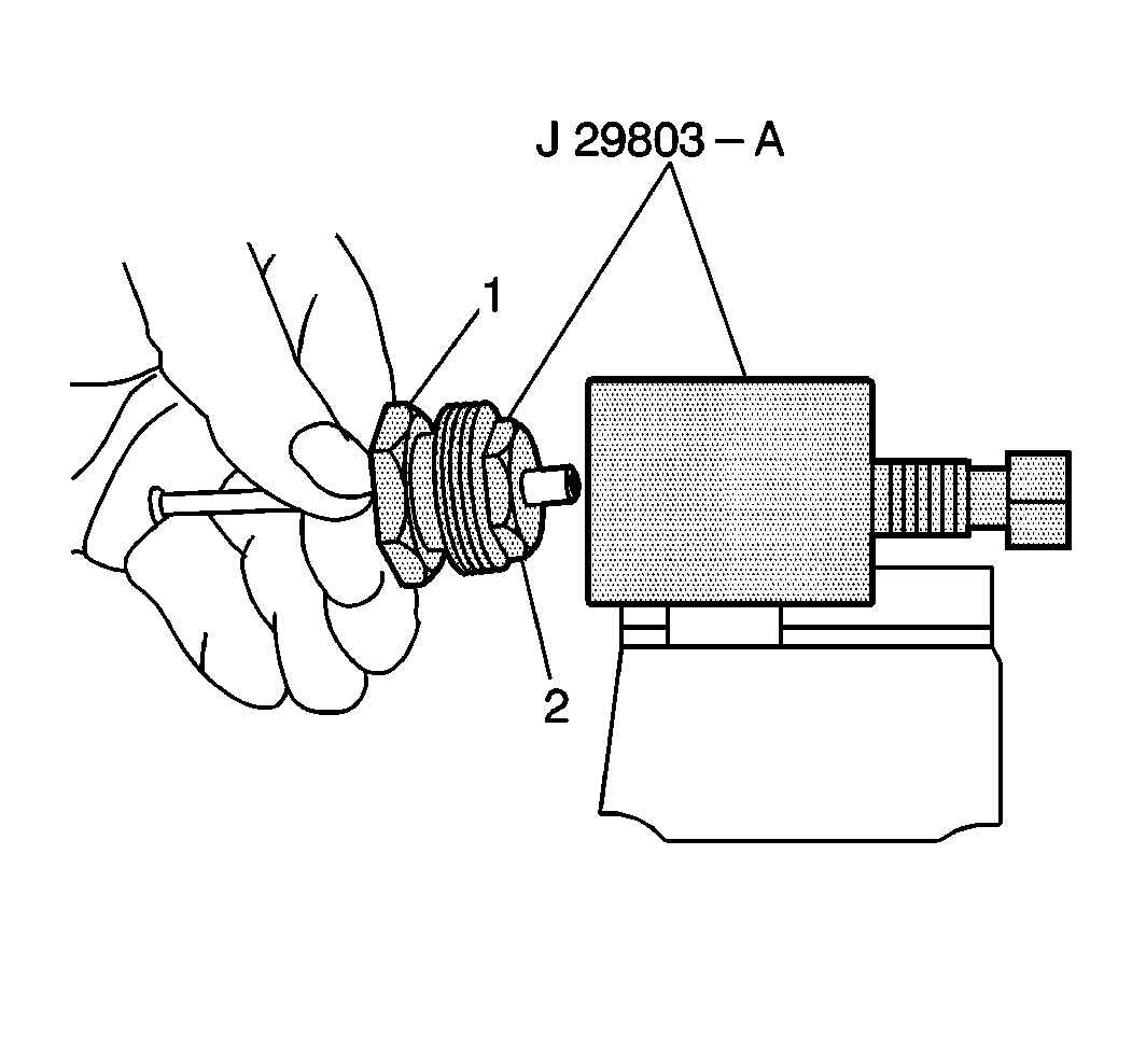
- Slide the clamping nut (1) over the tubing into the correct collet (2). Leave approximately 19 mm (0.750 in) of the tubing extending out of the collet (2).
- Insert the tubing into the tool body. Ensure that the tube end contacts the face of the forming mandrel.
- Tighten the clamping nut (1) into the tool body very tight in order to prevent the tube from pushing out.
- Wrench tighten the forcing screw in until the screw bottoms. Do not overtighten the forcing screw or the flare may become oversized.
- Back the clamping nut out of the tool body. Disassemble the clamping nut and collet.
- The flare is now ready for use.
- Bend the new brake pipe in order to match the old pipe. Use a tube bender.


| • | Maintain a minimum clearance of 19 mm (0.750 in) from all moving components, unless the brake pipe is clipped to the component. |
| • | Maintain a minimum clearance of 13 mm (0.50 in) from all vibrating components, unless the brake pipe is clipped to the component. |
| • | For armor wrapped pipe, contact is permissible if there is no relative movement between the pipe and the contact surface. |
