Power Steering Pump Flow Control Valve Replacement - Off Vehicle Control Valve
Removal Procedure
- Remove power steering pump assembly. Refer to Power Steering Pump Replacement for 3.8L V6 or Power Steering Pump Replacement for 5.7L V8.
- Remove powers steering gear inlet hose (1) from hydraulic pump fitting (2).
- Remove hydraulic pump fitting (2) and O-ring seal (3) from pump (6).
- Remove the flow control valve (4) and valve spring (5) from pump (6) cavity using magnet.
- Inspect flow control valve (4) for free movement within housing bore. If sticking occurs, check for burrs and clean as necessary. If necessary, replace flow control valve (4).
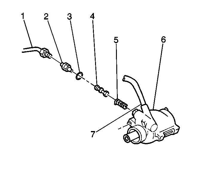
Important: The flow control valve must be installed in the same orientation it was in when removed or flow control and pressure relief will be affected.
Important: Do not disassemble the flow control valve (4).
Installation Procedure
- Install the valve spring (5) and flow control valve (4) into pump (6) cavity.
- Install new O-ring (3) to fitting (2).
- Hand start fitting (2) and O-ring seal (3) to pump (6). Once fitting is seated by hand, then tighten.
- Install inlet hose (1) to fitting (2).
- Install the power steering pump assembly. Refer to Power Steering Pump Replacement for 3.8L V6 or Power Steering Pump Replacement for 5.7L V8.
- Fill reservoir with fluid and bleed system. Refer to Power Steering System Bleeding in Power Steering.
Important: The flow control valve (4) should be installed face out, away from contact with the valve spring (5).
Important: Lubricate O-ring seal (3) with power steering fluid.
Tighten
Fitting to 75N·m (55 lb. ft.).
Tighten
Inlet hose (1) to 28N·m (21 lb. ft.).
Power Steering Pump Flow Control Valve Replacement - Off Vehicle Return Tube
Disassembly Procedure
- Inspect the return tube (2) on hydraulic pump housing assembly (1).
- Remove the O-ring union fitting (5) from the hydraulic pump housing assembly (1).
- Remove the O-ring seal (4) from the O-ring union fitting (5).
- Remove the control valve assembly (3).
- Remove the flow control spring (2).

Important: Handle the pump with care. Do not carry the hydraulic pump housing assembly (1) by the return tube (2).
Important: Replace the hydraulic pump housing assembly (1) if the return tube (2) is cracked or loose. Do not attempt to repair the hydraulic pump housing assembly (1).

Assembly Procedure
- Install the flow control spring (2) to the hydraulic pump housing assembly (1).
- Install the control valve assembly (3).
- Lubricate the O-ring seal (4) with power steering fluid.
- Install the O-ring seal (4) on to the O-ring union fitting (5).
- Install the O-ring union fitting (5) into the hydraulic pump housing assembly (1).
Notice: Use the correct fastener in the correct location. Replacement fasteners must be the correct part number for that application. Fasteners requiring replacement or fasteners requiring the use of thread locking compound or sealant are identified in the service procedure. Do not use paints, lubricants, or corrosion inhibitors on fasteners or fastener joint surfaces unless specified. These coatings affect fastener torque and joint clamping force and may damage the fastener. Use the correct tightening sequence and specifications when installing fasteners in order to avoid damage to parts and systems.
Tighten
Tighten the O-ring union fitting (5) to 75 N·m (55 lb ft).
