For 1990-2009 cars only
Removal Procedure
- Remove the I/P carrier. Refer to Instrument Panel Carrier Replacement in Instrument Panel, Gauges and Console.
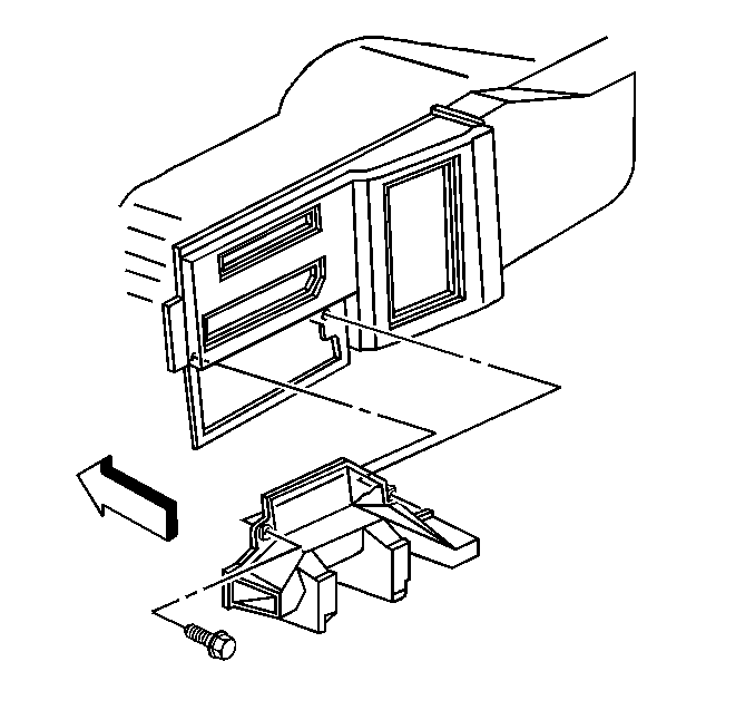
- Remove the front floor air outlet bolt.
- Remove the front floor air outlet.
- Remove the module cover screws.
- Remove the module cover.
- Remove the screw from the bi-level mode linkage.
- Remove the bi-level actuator and linkage.

Installation Procedure
- Install the bi-level actuator and linkage.
- Install the bi-level mode valve linkage screw.
- Install the module cover.
- Install the module cover screws.
- Install the front floor air outlet.
- Install the front floor air outlet bolt.
- Install the I/P carrier. Refer to Instrument Panel Carrier Replacement in Instrument Panel, Gauges and Console.
Tighten
Tighten the bi-level mode valve linkage screw to 2.3 N·m
(20 lb in).

Tighten
Tighten the front floor air outlet bolt to 1.9 N·m (17 lb in).
