| Table 1: | Antenna System Resistance Values |

Important: Remove the negative lead of the battery and zero the meter before measuring
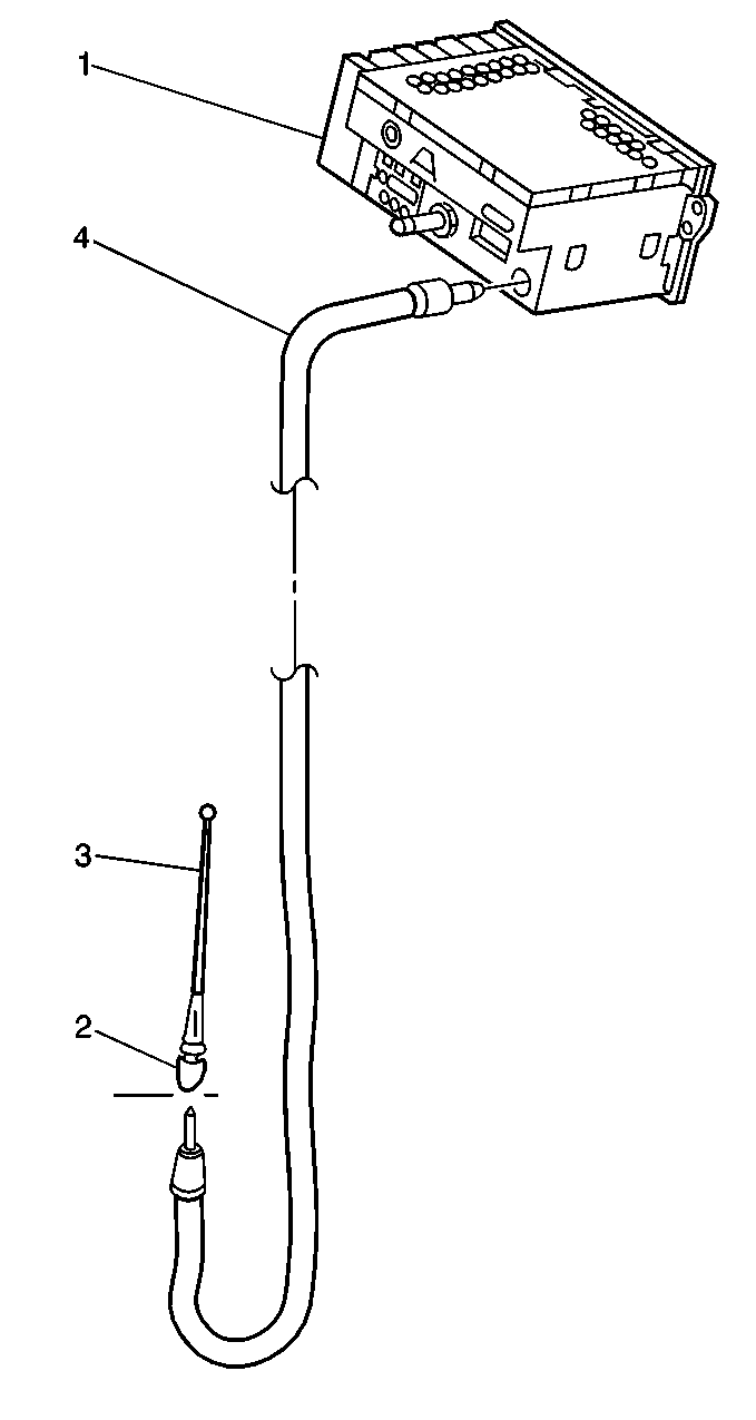
the resistance of the antenna. Wiggle the following components cautiously
during inspection:
• The antenna mast (3) • The lead-in tip (2) • The lead-in cable (4)
Important: The following readings must be obtained. If the readings are other than those listed some portion of the lead-in is intermittent. Replace the lead-in.
Digital Multimeter Probe Points | Resistance Measured in ohms |
|---|---|
A and B | less than 0.15 |
A and G | less than 0.15 |
B and C | less than 0.15 |
B and G | less than 0.15 |
A and D | Infinite |
B and D | Infinite |
B and E | Infinite |
B and H | Infinite |
A and E | Infinite |
A and H | Infinite |
A and C | less than 0.15 |
D and H (RG-62 and RG-62M) | less than 3.5 |
D and H (RG-58 and RG-59) | less than 0.2 |
D and B | Infinite |
D and G | Infinite |
D and C | Infinite |
E and C | Infinite |
D and E (RG-62 and RG-62M) | less than 3.5 |
D and E (RG-58 and RG-59) | less than 0.2 |
Step | Action | Value(s) | Yes | No |
|---|---|---|---|---|
1 |
Is the resistance value greater than the specified value? | 0.15 ohms | Go to Step 2 | Go to Step 5 |
2 | Inspect the base of the antenna. Is the connection good to the body ground? | -- | Go to Step 3 | Go to Step 6 |
3 | Inspect the coaxial cable interconnects for a poor connection or corrosion. Is either symptom present? | -- | Go to Step 4 | Go to Step 6 |
4 | Inspect the ground connection from the battery negative cable to the body. Is the connection good? | -- | Go to Step 5 | Go to Step 6 |
5 |
Does the meter indicate intermittent continuity? | -- | Go to Step 2 | Go to Step 7 |
6 | Repair the antenna ground circuit. Refer to Antenna Mast Cleaning . Is the repair complete? | -- | -- | |
7 | Measure the resistance between the radio coax lead-in connector (center conductor) and the antenna mast, with the DMM. Does the measured resistance approximately equal the specified values? | RG-58/RG-59: Less than 0.2 ohms RG-62/RG-62M: Less than 3.5 ohms | Go to Step 8 | Go to Step 3 |
8 | Wiggle the antenna coax while observing the DMM. Does the meter indicate intermittent continuity? | -- | Go to Step 9 | System OK |
9 | Inspect the coaxial cable interconnects for a poor connection or corrosion. Is either symptom present? | -- | Go to Step 10 | System OK |
10 | Repair/Replace the antenna coaxial circuit. Refer to Power Antenna Motor Replacement . Is the repair complete? | -- | -- |
