Removal Procedure
- Remove the rear axle shafts.
- On vehicles with standard non-traction control rear axles, remove the sensor plug mounting bolt/screw from the wheel speed sensor.
- On vehicles with standard non-traction control rear axles, remove the wheel speed sensor.
- Remove the differential carrier bearing cap bolts/screws.
- Remove the differential bearing shims.
- Remove the differential case from the rear axle housing.
Refer to Axle Shaft Replacement .
Refer to
Rear Axle With Antilock Brake System (Drum Brakes)
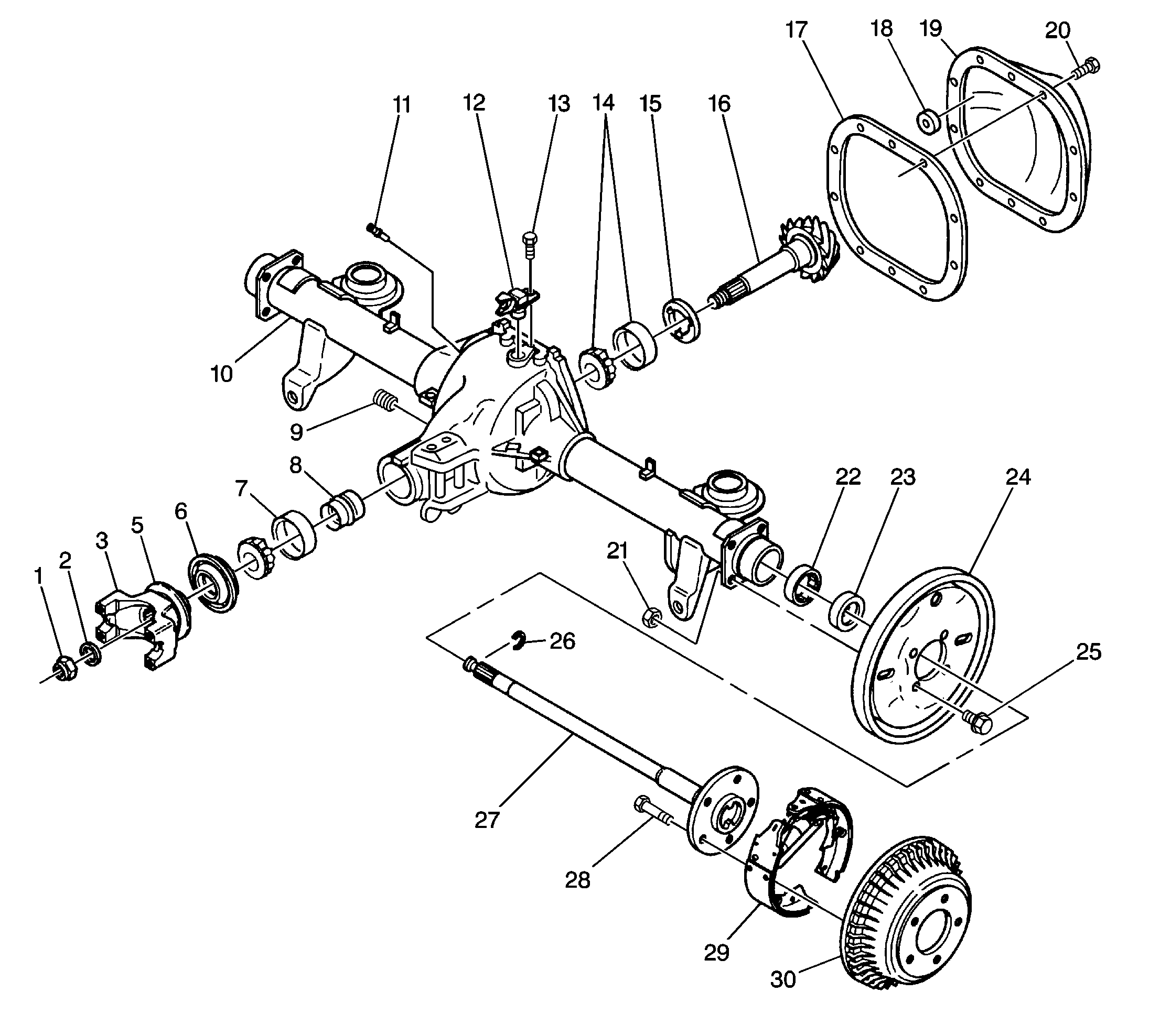
Carefully place the wheel speed sensor along the side of the rear axle housing.
Refer to
Rear Axle With Antilock Brake System (Drum Brakes)

Refer to
Rear Axle With Antilock Brake System and Differential Assembly
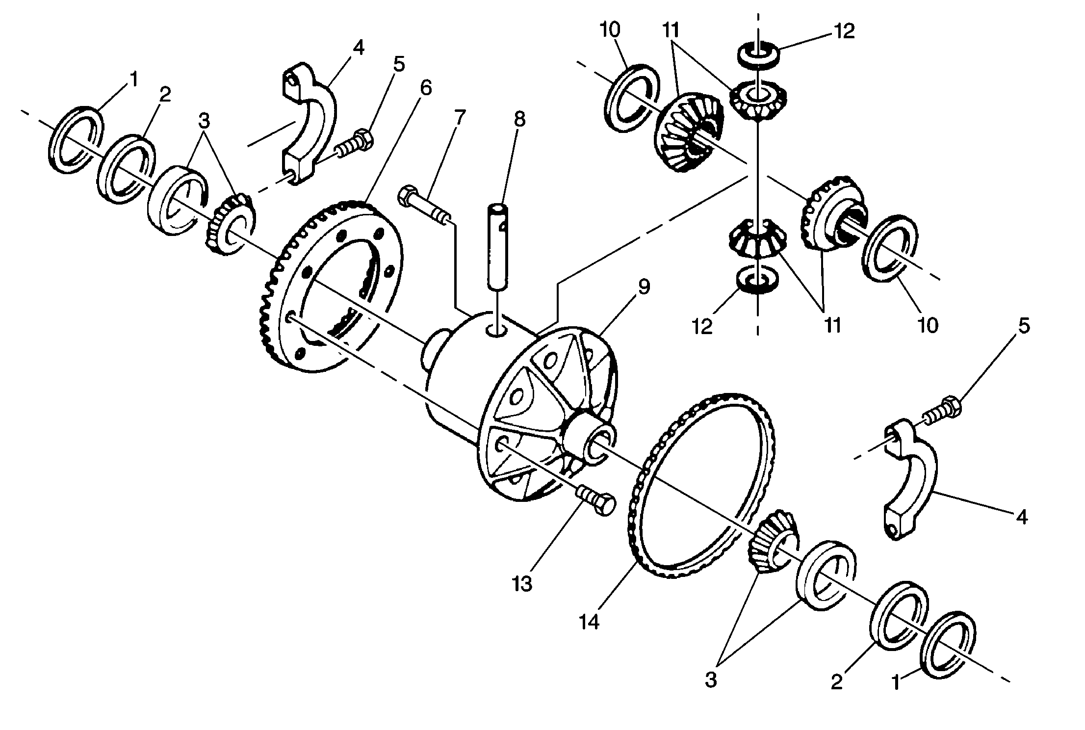
Important: Mark the differential carrier bearing caps R and L. This will ensure that they can be reassembled into their original positions.
Place the following components with the marked right and left differential bearings caps:| • | The right and left bearing outer races of the differential (side) bearings |
| • | The bearing shims |
Refer to
Rear Axle With Antilock Brake System and Differential Assembly

or
(1) Differential Bearing Shim (2) Differential
Bearing Spacer (3) Differential Bearing (4) Differential Carrier Bearing Cap (5) Differential
Carrier Bearing Cap Bolt/Screw (6) Differential Ring Gear (7) Differential Pinion Gear Shaft Lock
Bolt/Screw (8) Differential Pinion Gear Shaft (9) Differential Case (10) Front Differential
Side Gear Thrust Washer (11) Differential Pinion Gear (12) Differential
Pinion Thrust Washer (13) Differential Ring Gear Bolt/Screw (14) Rear Wheel Speed Sensor Reluctor
Wheel Rear Axle With Antilock Brake and Traction Control Systems Differential
Assembly
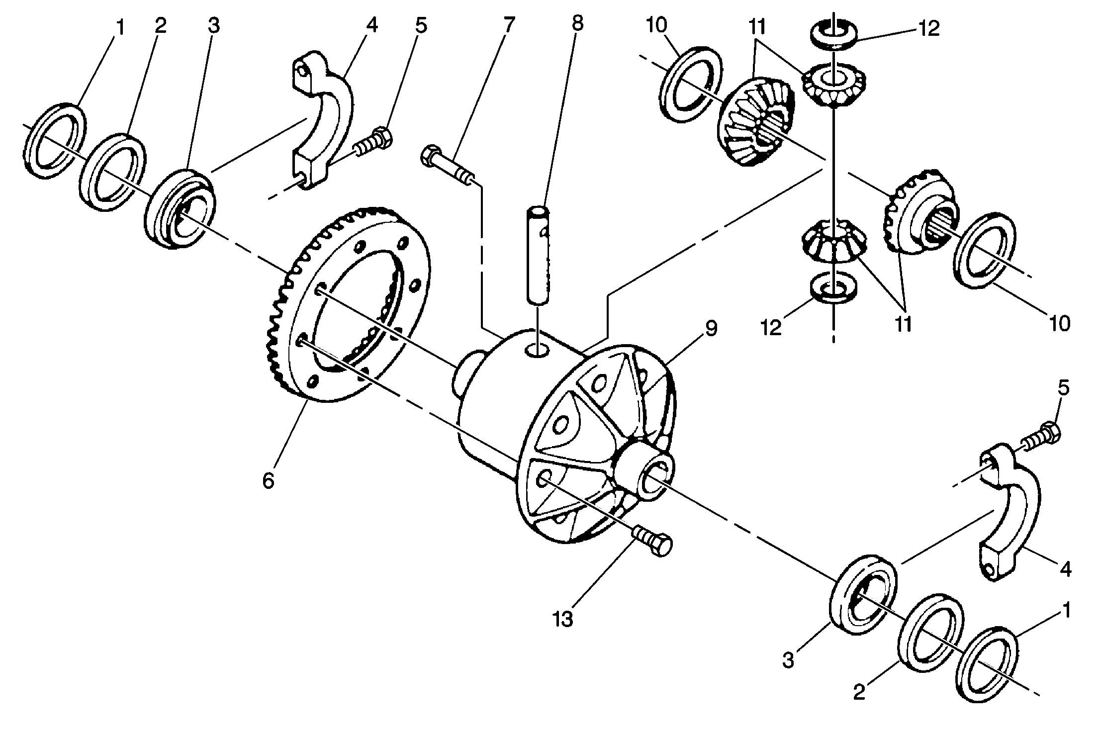
(1) Differential Bearing Shim (2) Differential
Bearing Spacer (3) Differential Bearing (4) Differential Carrier Bearing Cap (5) Differential
Carrier Bearing Cap Bolt/Screw (6) Differential Ring Gear (7) Differential Pinion Gear Shaft Lock
Bolt/Screw (8) Differential Pinion Gear Shaft (9) Differential Case (10) Front Differential
Side Gear Thrust Washer (11) Differential Pinion Gear (12) Differential Pinion Thrust Washer (13) Differential Ring Gear Bolt/Screw
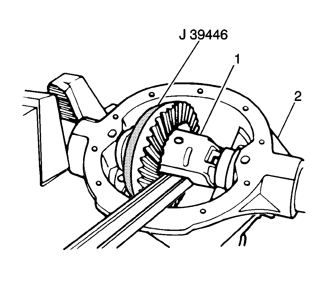
Notice: Be careful when prying the differential case out of the axle housing to prevent damage of the cover gasket surface. Support the differential case during removal to prevent case from falling and being damaged.
Important: Before removing the differential case from the rear axle housing, measure the differential ring gear-to-differential drive pinion gear backlash.
Refer to Backlash AdjustmentDisassembly Procedure
Tools Required
| • | J 22888-20A Differential Side Bearing Remover |
| • | J 8107-2 Differential Side Bearing Remover Plug |
| • | J 34168 Bearing Separator |
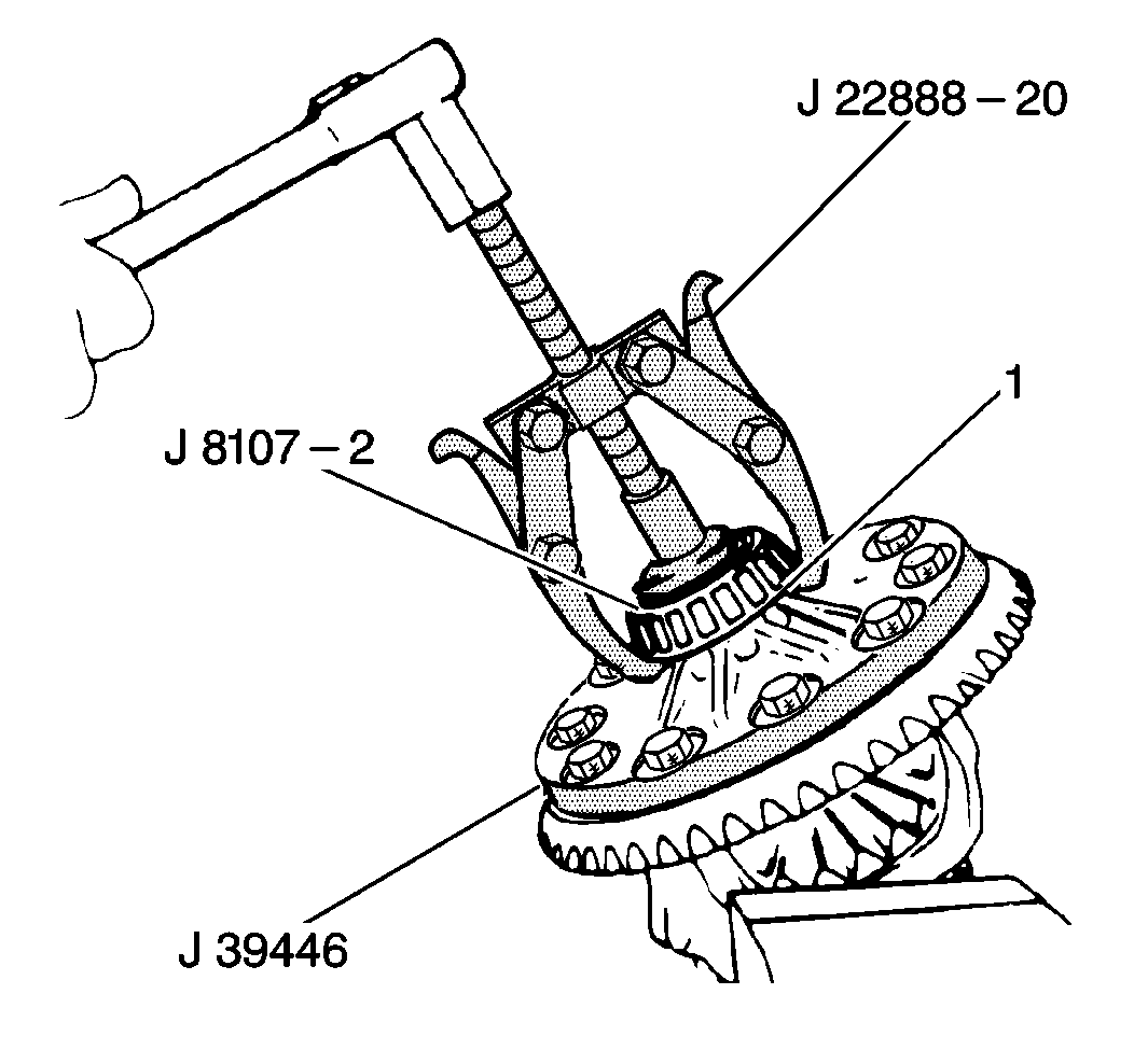
- Use the J 22888-20A and the J 8107-2 in order to remove the differential (side) bearing from the differential case.
- If a J 22888-20A will not fit use a J 34168 Bearing Separator to press the bearings off. (If removing an Auburn type limited slip differential case, skip Step 2.
- Remove the following components from the differential case:
- Remove all of the ring gear bolts/screws from the differential case.
- Use a brass drift and a hammer in order to drive the ring gear from the differential case.
- Use a brass hammer in order to remove the speed sensor reluctor wheel (14).
- Discard the speed sensor reluctor wheel.
| • | The upper and lower pinion gears |
| • | The pinion thrust washer |
| • | The left and right pinion gears |
| • | The differential side gear thrust washers |
| • | Mark the pinion gears and the differential case so the pinion gears may be reinstalled in the original positions. |
| • | Refer to
Rear Axle With Antilock Brake System and Differential Assembly
Rear Axle With Antilock Brake and Traction Control Systems Differential Assembly
|
The differential ring gear bolts/screws are the left-hand thread type bolts/screws.
Discard the ring gear bolts/screws.
Refer to
Rear Axle With Antilock Brake System and Differential Assembly

or
(1) Differential Bearing Shim (2) Differential
Bearing Spacer (3) Differential Bearing (4) Differential Carrier Bearing Cap (5) Differential
Carrier Bearing Cap Bolt/Screw (6) Differential Ring Gear (7) Differential Pinion Gear Shaft Lock
Bolt/Screw (8) Differential Pinion Gear Shaft (9) Differential Case (10) Front Differential
Side Gear Thrust Washer (11) Differential Pinion Gear (12) Differential
Pinion Thrust Washer (13) Differential Ring Gear Bolt/Screw (14) Rear Wheel Speed Sensor Reluctor
Wheel Rear Axle With Antilock Brake and Traction Control Systems Differential
Assembly

(1) Differential Bearing Shim (2) Differential
Bearing Spacer (3) Differential Bearing (4) Differential Carrier Bearing Cap (5) Differential
Carrier Bearing Cap Bolt/Screw (6) Differential Ring Gear (7) Differential Pinion Gear Shaft Lock
Bolt/Screw (8) Differential Pinion Gear Shaft (9) Differential Case (10) Front Differential
Side Gear Thrust Washer (11) Differential Pinion Gear (12) Differential Pinion Thrust Washer (13) Differential Ring Gear Bolt/Screw
Do not pry between the ring gear, the speed sensor reluctor wheel and the differential case if the ring gear tightly attached.
Refer to
Rear Axle With Antilock Brake System and Differential Assembly

or
(1) Differential Bearing Shim (2) Differential
Bearing Spacer (3) Differential Bearing (4) Differential Carrier Bearing Cap (5) Differential
Carrier Bearing Cap Bolt/Screw (6) Differential Ring Gear (7) Differential Pinion Gear Shaft Lock
Bolt/Screw (8) Differential Pinion Gear Shaft (9) Differential Case (10) Front Differential
Side Gear Thrust Washer (11) Differential Pinion Gear (12) Differential
Pinion Thrust Washer (13) Differential Ring Gear Bolt/Screw (14) Rear Wheel Speed Sensor Reluctor
Wheel Rear Axle With Antilock Brake and Traction Control Systems Differential
Assembly

(1) Differential Bearing Shim (2) Differential
Bearing Spacer (3) Differential Bearing (4) Differential Carrier Bearing Cap (5) Differential
Carrier Bearing Cap Bolt/Screw (6) Differential Ring Gear (7) Differential Pinion Gear Shaft Lock
Bolt/Screw (8) Differential Pinion Gear Shaft (9) Differential Case (10) Front Differential
Side Gear Thrust Washer (11) Differential Pinion Gear (12) Differential Pinion Thrust Washer (13) Differential Ring Gear Bolt/Screw
Important: Replace the speed sensor reluctor wheel if the speed sensor reluctor wheel is removed from vehicles with standard rear axles.
Refer toRear Axle With Antilock Brake System and Differential Assembly

| (1) | Differential Bearing Shim |
| (2) | Differential Bearing Spacer |
| (3) | Differential Bearing |
| (4) | Differential Carrier Bearing Cap |
| (5) | Differential Carrier Bearing Cap Bolt/Screw |
| (6) | Differential Ring Gear |
| (7) | Differential Pinion Gear Shaft Lock Bolt/Screw |
| (8) | Differential Pinion Gear Shaft |
| (9) | Differential Case |
| (10) | Front Differential Side Gear Thrust Washer |
| (11) | Differential Pinion Gear |
| (12) | Differential Pinion Thrust Washer |
| (13) | Differential Ring Gear Bolt/Screw |
| (14) | Rear Wheel Speed Sensor Reluctor Wheel |
Refer to
Rear Axle With Antilock Brake System and Differential Assembly

(1) Differential Bearing Shim (2) Differential
Bearing Spacer (3) Differential Bearing (4) Differential Carrier Bearing Cap (5) Differential
Carrier Bearing Cap Bolt/Screw (6) Differential Ring Gear (7) Differential Pinion Gear Shaft Lock
Bolt/Screw (8) Differential Pinion Gear Shaft (9) Differential Case (10) Front Differential
Side Gear Thrust Washer (11) Differential Pinion Gear (12) Differential
Pinion Thrust Washer (13) Differential Ring Gear Bolt/Screw (14) Rear Wheel Speed Sensor Reluctor
Wheel
Assembly Procedure
Tools Required
| • | J 8092 Driver Handle |
| • | J 21465-13 Driver Handle Extension |
| • | J 25299 Differential Side Bearing Installer |
- Lubricate all of the components of the differential before assembly.
- Clean the connecting surfaces of the ring gear and the differential case.
- On vehicles with a non-traction control rear axle, place the speed sensor reluctor wheel over the differential case on the ring gear side.
- On vehicles with a non-traction control rear axle, position the ring gear over the speed sensor reluctor wheel.
- Install two ring gear bolts/screws into opposite sides of the ring gear.
- Install the remaining new ring gear bolts/screws.
- Position the side gear thrust washers over the side gear hubs.
- Install the pinion gears into the differential case.
- Position one upper or lower pinion gear (without a pinion thrust washer) between the left pinion gear and the right pinion gear.
- Position the other pinion gear between the left and the right pinion side gears so that the pinion gear shaft holes are aligned.
- Rotate the upper and the lower pinion gears back toward the loading opening enough to permit sliding in the pinion thrust washers.
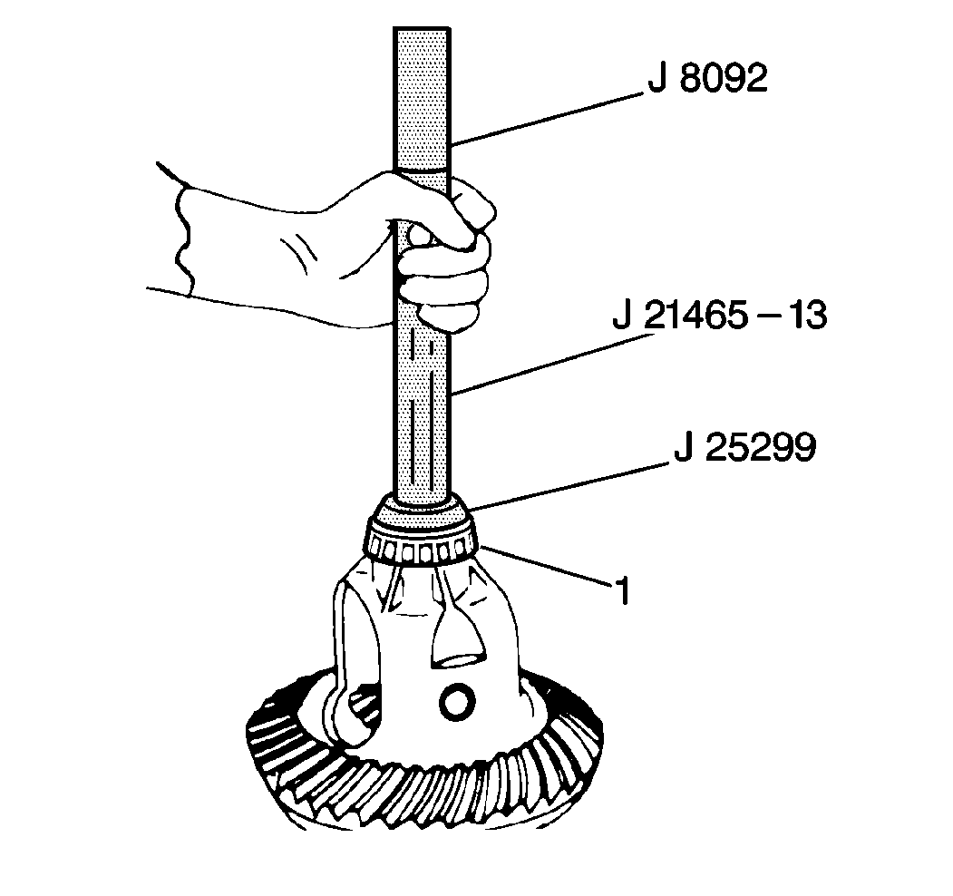
- Use the J 8092 , the J 21465-13 and the J 25299 in order to install the differential bearings (1) to the differential case.
Use one of the following lubricants:
| • | Axle lubricant |
| • | SAE 80W-90 GL-5 gear lubricant or an equivalent |
Refer to
Rear Axle With Antilock Brake System and Differential Assembly

or
(1) Differential Bearing Shim (2) Differential
Bearing Spacer (3) Differential Bearing (4) Differential Carrier Bearing Cap (5) Differential
Carrier Bearing Cap Bolt/Screw (6) Differential Ring Gear (7) Differential Pinion Gear Shaft Lock
Bolt/Screw (8) Differential Pinion Gear Shaft (9) Differential Case (10) Front Differential
Side Gear Thrust Washer (11) Differential Pinion Gear (12) Differential
Pinion Thrust Washer (13) Differential Ring Gear Bolt/Screw (14) Rear Wheel Speed Sensor Reluctor
Wheel Rear Axle With Antilock Brake and Traction Control Systems Differential
Assembly

(1) Differential Bearing Shim (2) Differential
Bearing Spacer (3) Differential Bearing (4) Differential Carrier Bearing Cap (5) Differential
Carrier Bearing Cap Bolt/Screw (6) Differential Ring Gear (7) Differential Pinion Gear Shaft Lock
Bolt/Screw (8) Differential Pinion Gear Shaft (9) Differential Case (10) Front Differential
Side Gear Thrust Washer (11) Differential Pinion Gear (12) Differential Pinion Thrust Washer (13) Differential Ring Gear Bolt/Screw
Caution: Once the speed sensor reluctor wheel has been removed from the differential case, a new speed sensor reluctor wheel must be installed. The press fit may be lost if the speed sensor reluctor wheel is used more than once. This would allow the speed sensor reluctor wheel to rotate freely on the differential case causing a significant reduction in performance of the antilock brake system, which could result in bodily injury.
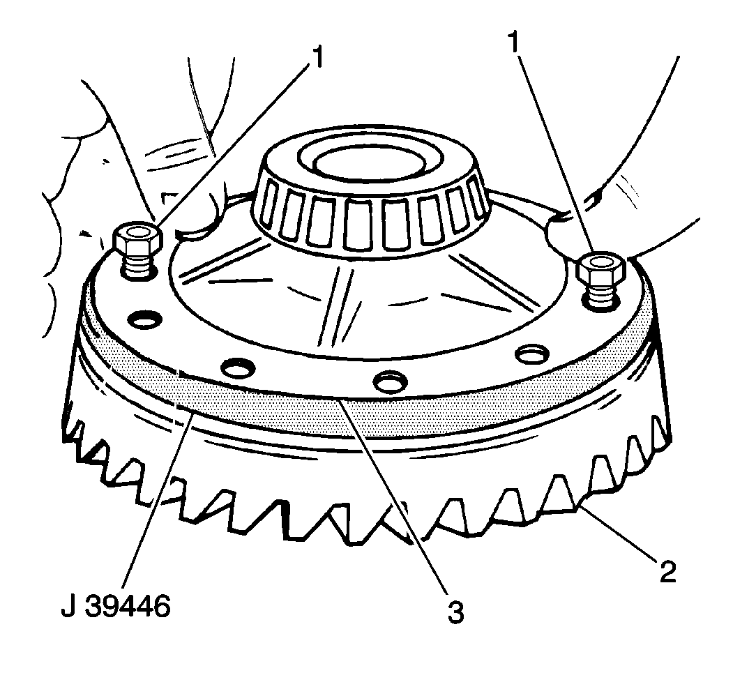
Install the speed sensor reluctor wheel.
Refer to
Rear Axle With Antilock Brake System and Differential Assembly

(1) Differential Bearing Shim (2) Differential
Bearing Spacer (3) Differential Bearing (4) Differential Carrier Bearing Cap (5) Differential
Carrier Bearing Cap Bolt/Screw (6) Differential Ring Gear (7) Differential Pinion Gear Shaft Lock
Bolt/Screw (8) Differential Pinion Gear Shaft (9) Differential Case (10) Front Differential
Side Gear Thrust Washer (11) Differential Pinion Gear (12) Differential
Pinion Thrust Washer (13) Differential Ring Gear Bolt/Screw (14) Rear Wheel Speed Sensor Reluctor
Wheel
Install the ring gear (2).
(If converting to an Auburn type limited slip differential case, skip to Step 12.
Notice: Use the correct fastener in the correct location. Replacement fasteners must be the correct part number for that application. Fasteners requiring replacement or fasteners requiring the use of thread locking compound or sealant are identified in the service procedure. Do not use paints, lubricants, or corrosion inhibitors on fasteners or fastener joint surfaces unless specified. These coatings affect fastener torque and joint clamping force and may damage the fastener. Use the correct tightening sequence and specifications when installing fasteners in order to avoid damage to parts and systems.
Finger tighten the new ring gear bolts/screws.
Tighten
Tighten the differential ring gear bolts/screws alternately in progressive stages to 120 N·m (89 lb ft).
If the original side gear thrust washers are being installed, install the side gear thrust washers in their original positions.
Refer to
Rear Axle With Antilock Brake System and Differential Assembly

or
(1) Differential Bearing Shim (2) Differential
Bearing Spacer (3) Differential Bearing (4) Differential Carrier Bearing Cap (5) Differential
Carrier Bearing Cap Bolt/Screw (6) Differential Ring Gear (7) Differential Pinion Gear Shaft Lock
Bolt/Screw (8) Differential Pinion Gear Shaft (9) Differential Case (10) Front Differential
Side Gear Thrust Washer (11) Differential Pinion Gear (12) Differential
Pinion Thrust Washer (13) Differential Ring Gear Bolt/Screw (14) Rear Wheel Speed Sensor Reluctor
Wheel Rear Axle With Antilock Brake and Traction Control Systems Differential
Assembly

(1) Differential Bearing Shim (2) Differential
Bearing Spacer (3) Differential Bearing (4) Differential Carrier Bearing Cap (5) Differential
Carrier Bearing Cap Bolt/Screw (6) Differential Ring Gear (7) Differential Pinion Gear Shaft Lock
Bolt/Screw (8) Differential Pinion Gear Shaft (9) Differential Case (10) Front Differential
Side Gear Thrust Washer (11) Differential Pinion Gear (12) Differential Pinion Thrust Washer (13) Differential Ring Gear Bolt/Screw
If the original pinion gears are being installed, install the pinion gears in their original positions.
Refer to
Rear Axle With Antilock Brake System and Differential Assembly

or
(1) Differential Bearing Shim (2) Differential
Bearing Spacer (3) Differential Bearing (4) Differential Carrier Bearing Cap (5) Differential
Carrier Bearing Cap Bolt/Screw (6) Differential Ring Gear (7) Differential Pinion Gear Shaft Lock
Bolt/Screw (8) Differential Pinion Gear Shaft (9) Differential Case (10) Front Differential
Side Gear Thrust Washer (11) Differential Pinion Gear (12) Differential
Pinion Thrust Washer (13) Differential Ring Gear Bolt/Screw (14) Rear Wheel Speed Sensor Reluctor
Wheel Rear Axle With Antilock Brake and Traction Control Systems Differential
Assembly

(1) Differential Bearing Shim (2) Differential
Bearing Spacer (3) Differential Bearing (4) Differential Carrier Bearing Cap (5) Differential
Carrier Bearing Cap Bolt/Screw (6) Differential Ring Gear (7) Differential Pinion Gear Shaft Lock
Bolt/Screw (8) Differential Pinion Gear Shaft (9) Differential Case (10) Front Differential
Side Gear Thrust Washer (11) Differential Pinion Gear (12) Differential Pinion Thrust Washer (13) Differential Ring Gear Bolt/Screw
Rotate the pinion gears until one of the upper or lower pinion gears is opposite the loading opening in the differential case.
Refer to
Rear Axle With Antilock Brake System and Differential Assembly

or
(1) Differential Bearing Shim (2) Differential
Bearing Spacer (3) Differential Bearing (4) Differential Carrier Bearing Cap (5) Differential
Carrier Bearing Cap Bolt/Screw (6) Differential Ring Gear (7) Differential Pinion Gear Shaft Lock
Bolt/Screw (8) Differential Pinion Gear Shaft (9) Differential Case (10) Front Differential
Side Gear Thrust Washer (11) Differential Pinion Gear (12) Differential
Pinion Thrust Washer (13) Differential Ring Gear Bolt/Screw (14) Rear Wheel Speed Sensor Reluctor
Wheel Rear Axle With Antilock Brake and Traction Control Systems Differential
Assembly

(1) Differential Bearing Shim (2) Differential
Bearing Spacer (3) Differential Bearing (4) Differential Carrier Bearing Cap (5) Differential
Carrier Bearing Cap Bolt/Screw (6) Differential Ring Gear (7) Differential Pinion Gear Shaft Lock
Bolt/Screw (8) Differential Pinion Gear Shaft (9) Differential Case (10) Front Differential
Side Gear Thrust Washer (11) Differential Pinion Gear (12) Differential Pinion Thrust Washer (13) Differential Ring Gear Bolt/Screw
Rotate the pinion gears until the holes in the upper and the lower pinion gears are aligned with the holes in the differential case.
Refer to
Rear Axle With Antilock Brake System and Differential Assembly

or
(1) Differential Bearing Shim (2) Differential
Bearing Spacer (3) Differential Bearing (4) Differential Carrier Bearing Cap (5) Differential
Carrier Bearing Cap Bolt/Screw (6) Differential Ring Gear (7) Differential Pinion Gear Shaft Lock
Bolt/Screw (8) Differential Pinion Gear Shaft (9) Differential Case (10) Front Differential
Side Gear Thrust Washer (11) Differential Pinion Gear (12) Differential
Pinion Thrust Washer (13) Differential Ring Gear Bolt/Screw (14) Rear Wheel Speed Sensor Reluctor
Wheel Rear Axle With Antilock Brake and Traction Control Systems Differential
Assembly

(1) Differential Bearing Shim (2) Differential
Bearing Spacer (3) Differential Bearing (4) Differential Carrier Bearing Cap (5) Differential
Carrier Bearing Cap Bolt/Screw (6) Differential Ring Gear (7) Differential Pinion Gear Shaft Lock
Bolt/Screw (8) Differential Pinion Gear Shaft (9) Differential Case (10) Front Differential
Side Gear Thrust Washer (11) Differential Pinion Gear (12) Differential Pinion Thrust Washer (13) Differential Ring Gear Bolt/Screw
Installation Procedure
Tools Required
J 25588 Side Bearing Shim Installer
- Install the differential case into the rear axle housing.
- Use the following steps in order to install the differential bearing shims:
- Install the differential bearing cap bolts/screws (5).
- Measure the backlash.
- Install the rear axle shafts.
- Install the following components:
Refer to
Rear Axle With Antilock Brake System and Differential Assembly

or
(1) Differential Bearing Shim (2) Differential
Bearing Spacer (3) Differential Bearing (4) Differential Carrier Bearing Cap (5) Differential
Carrier Bearing Cap Bolt/Screw (6) Differential Ring Gear (7) Differential Pinion Gear Shaft Lock
Bolt/Screw (8) Differential Pinion Gear Shaft (9) Differential Case (10) Front Differential
Side Gear Thrust Washer (11) Differential Pinion Gear (12) Differential
Pinion Thrust Washer (13) Differential Ring Gear Bolt/Screw (14) Rear Wheel Speed Sensor Reluctor
Wheel Rear Axle With Antilock Brake and Traction Control Systems Differential
Assembly

(1) Differential Bearing Shim (2) Differential
Bearing Spacer (3) Differential Bearing (4) Differential Carrier Bearing Cap (5) Differential
Carrier Bearing Cap Bolt/Screw (6) Differential Ring Gear (7) Differential Pinion Gear Shaft Lock
Bolt/Screw (8) Differential Pinion Gear Shaft (9) Differential Case (10) Front Differential
Side Gear Thrust Washer (11) Differential Pinion Gear (12) Differential Pinion Thrust Washer (13) Differential Ring Gear Bolt/Screw
Important:
• Do not reinstall the production bearing shims. The production bearing shims may break when tapped by a hammer. • Service bearing shims are reusable. The differential bearings must have the original outer races in place when the bearings are reused. Refer to
Differential Carrier Bearing Preload Adjustment
. • Ensure that the bearing shim packs remain in each shim pack's proper position (right side or left side).
| 2.1. | Select the correct left side bearing shim. |
The bearing shim must be 0.10 mm (0.004 in) thicker than the shim that was removed from the left side.
| 2.2. | Insert the left side bearing shim pack between the spacer and the left bearing race. |
| 2.3. | Loosely install the carrier bearing cap. |
Refer to
Rear Axle With Antilock Brake System and Differential Assembly

or
(1) Differential Bearing Shim (2) Differential
Bearing Spacer (3) Differential Bearing (4) Differential Carrier Bearing Cap (5) Differential
Carrier Bearing Cap Bolt/Screw (6) Differential Ring Gear (7) Differential Pinion Gear Shaft Lock
Bolt/Screw (8) Differential Pinion Gear Shaft (9) Differential Case (10) Front Differential
Side Gear Thrust Washer (11) Differential Pinion Gear (12) Differential
Pinion Thrust Washer (13) Differential Ring Gear Bolt/Screw (14) Rear Wheel Speed Sensor Reluctor
Wheel Rear Axle With Antilock Brake and Traction Control Systems Differential
Assembly

(1) Differential Bearing Shim (2) Differential
Bearing Spacer (3) Differential Bearing (4) Differential Carrier Bearing Cap (5) Differential
Carrier Bearing Cap Bolt/Screw (6) Differential Ring Gear (7) Differential Pinion Gear Shaft Lock
Bolt/Screw (8) Differential Pinion Gear Shaft (9) Differential Case (10) Front Differential
Side Gear Thrust Washer (11) Differential Pinion Gear (12) Differential Pinion Thrust Washer (13) Differential Ring Gear Bolt/Screw
| 2.4. | Select the correct right side bearing shim. |
The bearing shim must be 0.10 mm (0.004 inch) thicker than the shim that was removed from the right side.
| 2.5. | Insert the bearing shim between the spacer and the right bearing race. |
| 2.6. | Use the J 25588 in order to drive the right bearing shim into position. |
Notice: Use the correct fastener in the correct location. Replacement fasteners must be the correct part number for that application. Fasteners requiring replacement or fasteners requiring the use of thread locking compound or sealant are identified in the service procedure. Do not use paints, lubricants, or corrosion inhibitors on fasteners or fastener joint surfaces unless specified. These coatings affect fastener torque and joint clamping force and may damage the fastener. Use the correct tightening sequence and specifications when installing fasteners in order to avoid damage to parts and systems.
Refer to
Rear Axle With Antilock Brake System and Differential Assembly

or
(1) Differential Bearing Shim (2) Differential
Bearing Spacer (3) Differential Bearing (4) Differential Carrier Bearing Cap (5) Differential
Carrier Bearing Cap Bolt/Screw (6) Differential Ring Gear (7) Differential Pinion Gear Shaft Lock
Bolt/Screw (8) Differential Pinion Gear Shaft (9) Differential Case (10) Front Differential
Side Gear Thrust Washer (11) Differential Pinion Gear (12) Differential
Pinion Thrust Washer (13) Differential Ring Gear Bolt/Screw (14) Rear Wheel Speed Sensor Reluctor
Wheel Rear Axle With Antilock Brake and Traction Control Systems Differential
Assembly

(1) Differential Bearing Shim (2) Differential
Bearing Spacer (3) Differential Bearing (4) Differential Carrier Bearing Cap (5) Differential
Carrier Bearing Cap Bolt/Screw (6) Differential Ring Gear (7) Differential Pinion Gear Shaft Lock
Bolt/Screw (8) Differential Pinion Gear Shaft (9) Differential Case (10) Front Differential
Side Gear Thrust Washer (11) Differential Pinion Gear (12) Differential Pinion Thrust Washer (13) Differential Ring Gear Bolt/Screw
Tighten
Tighten the differential carrier bearing cap bolts/screws to 75 N·m (55 lb ft).
Correct the backlash as necessary.
Refer to Backlash Adjustment
Refer to Axle Shaft Replacement
| • | The wheel speed sensor |
| • | Refer to
Rear Axle With Antilock Brake System (Drum Brakes)
Rear Axle With Antilock Brake and Traction Control Systems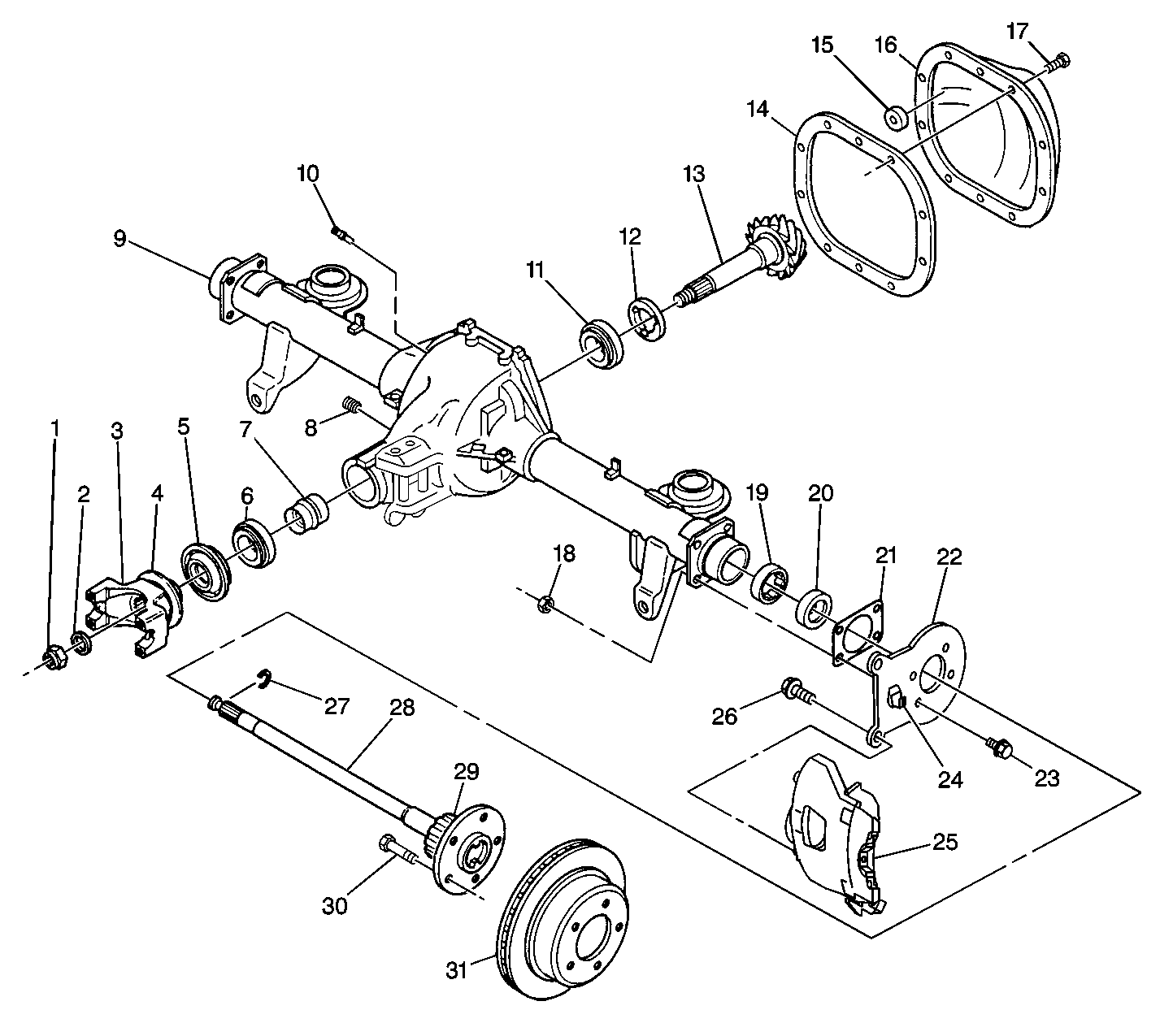
|
| • | The wheel speed sensor mounting bolt/screw |
| • | Refer to
Rear Axle With Antilock Brake System and Differential Assembly
|
Tighten
Tighten the wheel speed sensor mounting plug bolt/screw to 10 N·m (89 lb in).
