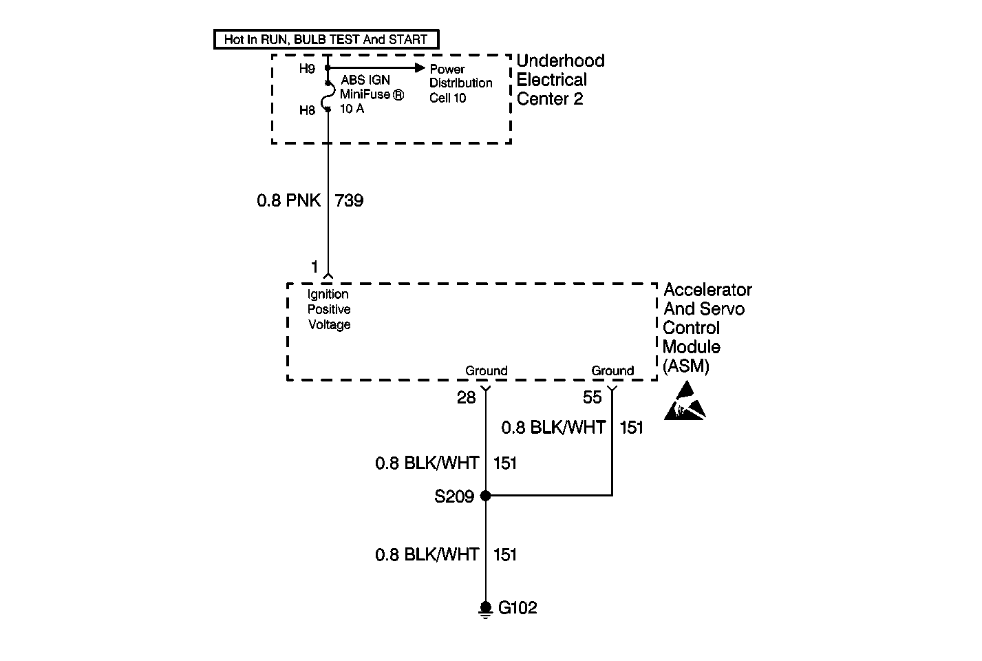
Circuit Description
This circuit monitors the voltage level available to the ASM. If the voltage drops below 7.5 volts, full performance of the traction control system cannot be guaranteed.
Conditions for Setting the DTC
DTC C0901 can set anytime the ignition is in the RUN position and ignition voltage is less than 7.5 volts
Action Taken When the DTC Sets
| • | The TCS is disabled |
| • | The traction control indicator is turned on |
Conditions for Clearing the DTC
| • | The condition for the DTC is no longer present and the scan tool clear DTC function is used |
| • | 100 ignition cycles have passed with no DTCs detected |
Diagnostic Aids
| • | Thoroughly inspect the wiring and the connectors. Failure to carefully and fully inspect the wiring and the connectors can result in misdiagnosis. Misdiagnosis may cause replacement of parts without repairing the malfunction. |
| • | Inspect for other low voltage conditions. |
| • | Test the charging system. Refer to Charging System Check in Engine Electrical. |
| • | The following conditions are other possible causes of low system voltage: |
| - | A charging system malfunction |
| - | Excessive parasitic drain |
| - | A weak battery |
| - | A faulty system ground |
| • | If an intermittent malfunction exists, refer to Troubleshooting Procedures Cell 4 in Electrical Diagnosis. |
Test Description
The numbers below refer to the step numbers on the diagnostic table.
Step | Action | Value(s) | Yes | No |
|---|---|---|---|---|
1 | Was the Diagnostic System Check performed? | -- | Go to Step 2 | |
2 | Check the Charging System. Refer to Charging System Check in Engine Electrical. Is the charging system OK? | -- | Go to Step 3 | Go to Charging System Check in Engine Electrical |
3 |
Is there any evidence of damage or corrosion? | -- | Go to Step 7 | Go to Step 4 |
Using the J 39200 DMM, measure the resistance between the ASM harness connector terminal 28 and a good ground. Is the resistance within specifications? | 0-5 ohms | Go to Step 5 | Go to Step 8 | |
5 | Using the J 39200 DMM, measure the resistance between the ASM harness connector terminal 55 and a good ground. s the resistance within specifications? | 0-5 ohms | Go to Step 6 | Go to Step 8 |
Is the voltage more than the specified value? | 7.5 V | Go to Step 9 | Go to Battery Charging in Engine Electrical | |
7 | Repair as necessary. Are the repairs complete? | -- | -- | |
8 | Repair the open or high resistance in CKT 151. Refer to Repair Procedures Cell 5 in Electrical Diagnosis. Is the circuit repair complete? | -- | -- | |
9 | Replace the ASM. Refer to Accelerator and Servo Control Module Replacement . Is the replacement complete? | -- | -- |
