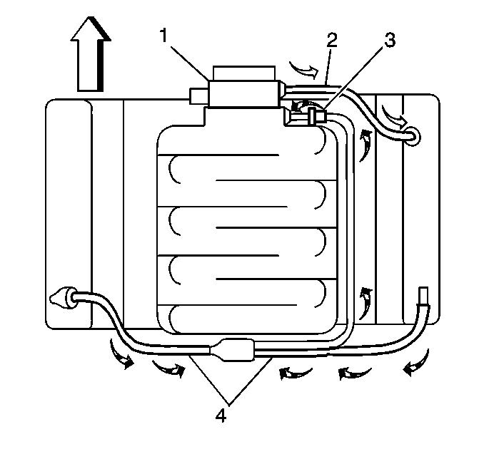
A closed crankcase ventilation system is used to provide a more complete scavenging of crankcase vapors. Fresh air from the throttle body is supplied to the crankcase, mixed with blow-by gases and then passed through a crankcase ventilation valve into the intake manifold.
The primary control is through the crankcase ventilation valve which meters the flow at a rate depending on manifold vacuum. To maintain idle quality, the crankcase ventilation valve restricts the flow when intake manifold vacuum is high. If abnormal operating conditions arise, the system is designed to allow excessive amounts of blow-by gases to back flow through the crankcase vent tube into the engine air inlet to be consumed by normal combustion.
The engine ventilation system was developed to minimize oil consumption and ensure that oil ingestion could not occur during vehicle limit handling maneuverers. Filtered fresh air is routed from up stream of the throttle blade to the front of the right rocker cover via a formed rubber hose. To reduce the potential of oil pullover into the throttle bore area due to back flow of the ventilation system, the fitting in the right side rocker cover is located between a shield from the rocker arms. Blow-by gases are routed from the rear of both rocker covers, through molded nylon lines to a tee fitting located on the centerline of the engine at the rear of the intake manifold. From there, a single nylon line carries the foul air gases through an externally mounted, horizontal PCV valve and enters the intake manifold behind the throttle body.
The dual draw system was develop to meet the limited handling maneuver requirements. During sustained maximum lateral accelerations, the outboard rocker cover may fill with oil. The dual draw system passively switches, allowing the PCV valve to draw on the rocker cover with the least resistance. This results in the system drawing on the air filled, or inboard rocker cover and eliminates oil pullover due to drawing on the oil-filled outboard rocker cover.
Crankcase Ventilation System Routing

