For 1990-2009 cars only
Removal Procedure
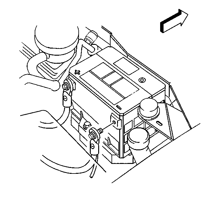
- Disconnect the negative battery cable. Refer to Battery Negative Cable Disconnection and Connection in Engine Electrical.
- Remove the inflatable restraint coil. Refer to Inflatable Restraint Steering Wheel Module Coil Replacement in Restraints.
- Insert the ignition key into the lock cylinder.
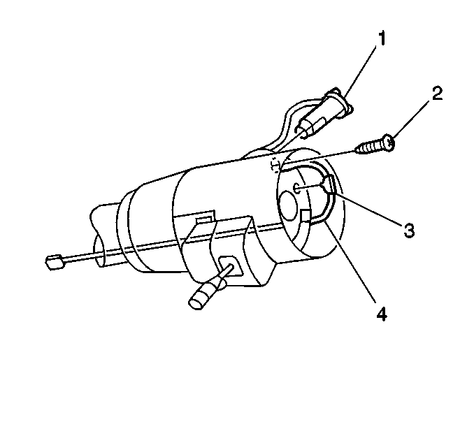
- Remove the lock retaining screw (2).
- Remove the lock cylinder (1) and harness (4), perform the following:


Leave the key in the LOCK position.

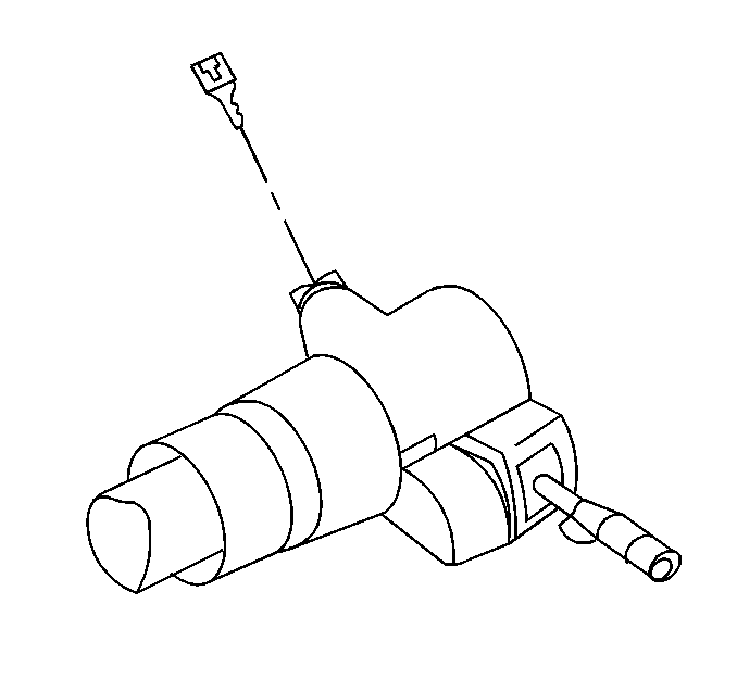
| • | Disconnect the terminal connector from the bulkhead connector. |
| • | Remove the wiring protector. |
| • | Disconnect the retaining clip (3) from the lock housing cover sleeve. |
| • | Gently pull wire harness (4) through the column. |
| • | Remove the lock cylinder (1) from the vehicle. |
Installation Procedure
- Install the lock cylinder (1) and harness (4), perform the following:
- Install the lock retaining screw (2).
- Remove the ignition key from the lock cylinder.
- Install the inflatable restraint coil. Refer to Inflatable Restraint Steering Wheel Module Coil Replacement in Restraints.
- Connect the negative battery cable. Refer to Battery Negative Cable Disconnection and Connection in Engine Electrical.

| • | Install the lock cylinder (1) to the vehicle. |
| • | Gently pull wire harness (4) through the column. |
| • | Connect the retaining clip (3) to the lock housing cover sleeve. |
| • | Install the wiring protector. |
| • | Connect the terminal connector to the bulkhead connector. |
Tighten
Tighten the lock retaining screw to 2.5 N·m (22 lb in).


