For 1990-2009 cars only
Removal Procedure
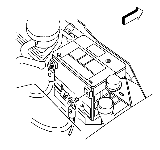
- Disconnect the negative battery cable. Refer to Battery Negative Cable Disconnection and Connection in Engine Electrical.
- Remove the right quarter inner rear trim finishing panel.
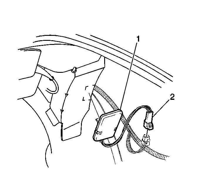
- Disconnect the shock sensor electrical connector (2).
- On the convertible, remove the shock sensor (1) from the wheelhouse bracket.
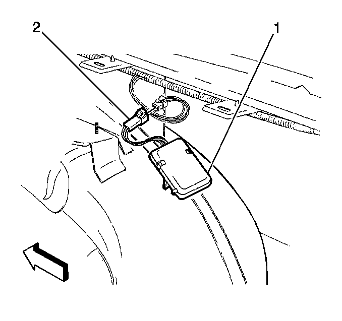
- Disconnect the shock sensor electrical connector (2).
- On the coupe, remove the shock sensor (1) from the right rear inner wheelhouse.
- Remove the shock sensor (2) from the vehicle.
- Clean the shock sensor mounting surface.


Installation Procedure
Important: The shock sensor sensitivity is preset and should not require adjustment. Remove the label covering and adjust only if more or less sensitivity is requested. Refer to System Components in Content Theft Deterrent (CTD) Operation.
- Remove the paper backing from the shock sensor (1).
- Connect the shock sensor (2) electrical connector.
- Remove the paper backing from the shock sensor (1).
- On the convertible, install the shock sensor (1) from the wheelhouse bracket.
- Connect the shock sensor electrical connector (2).
- Remove the right quarter inner rear trim finishing panel.
- Connect the negative battery cable. Refer to Battery Negative Cable Disconnection and Connection in Engine Electrical.

On the coupe, install the shock sensor (1) to the right rear inner wheelhouse.


