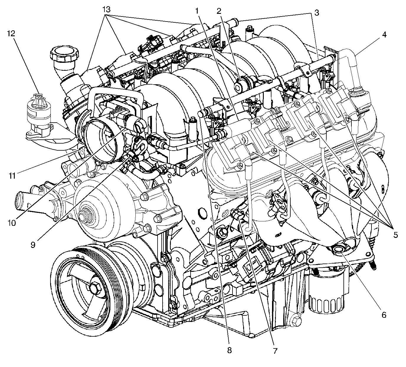
| Figure 1: |
Full Engine View LH Side
|
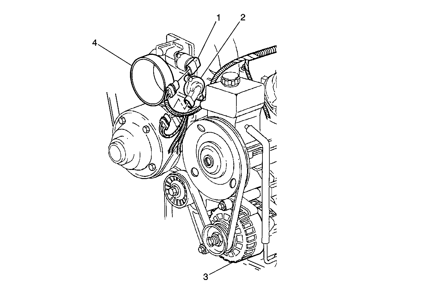
| Figure 2: |
Idle Air Control (IAC) Motor, Throttle Position (TP) Sensor, Generator
|
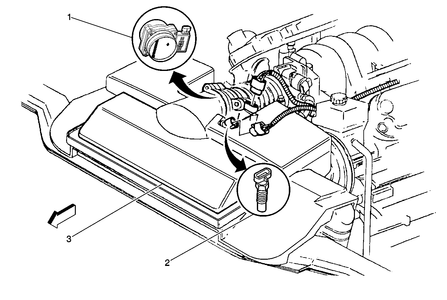
| Figure 3: |
Mass Air Flow Sensor and Intake Air Temperature Sensor
|
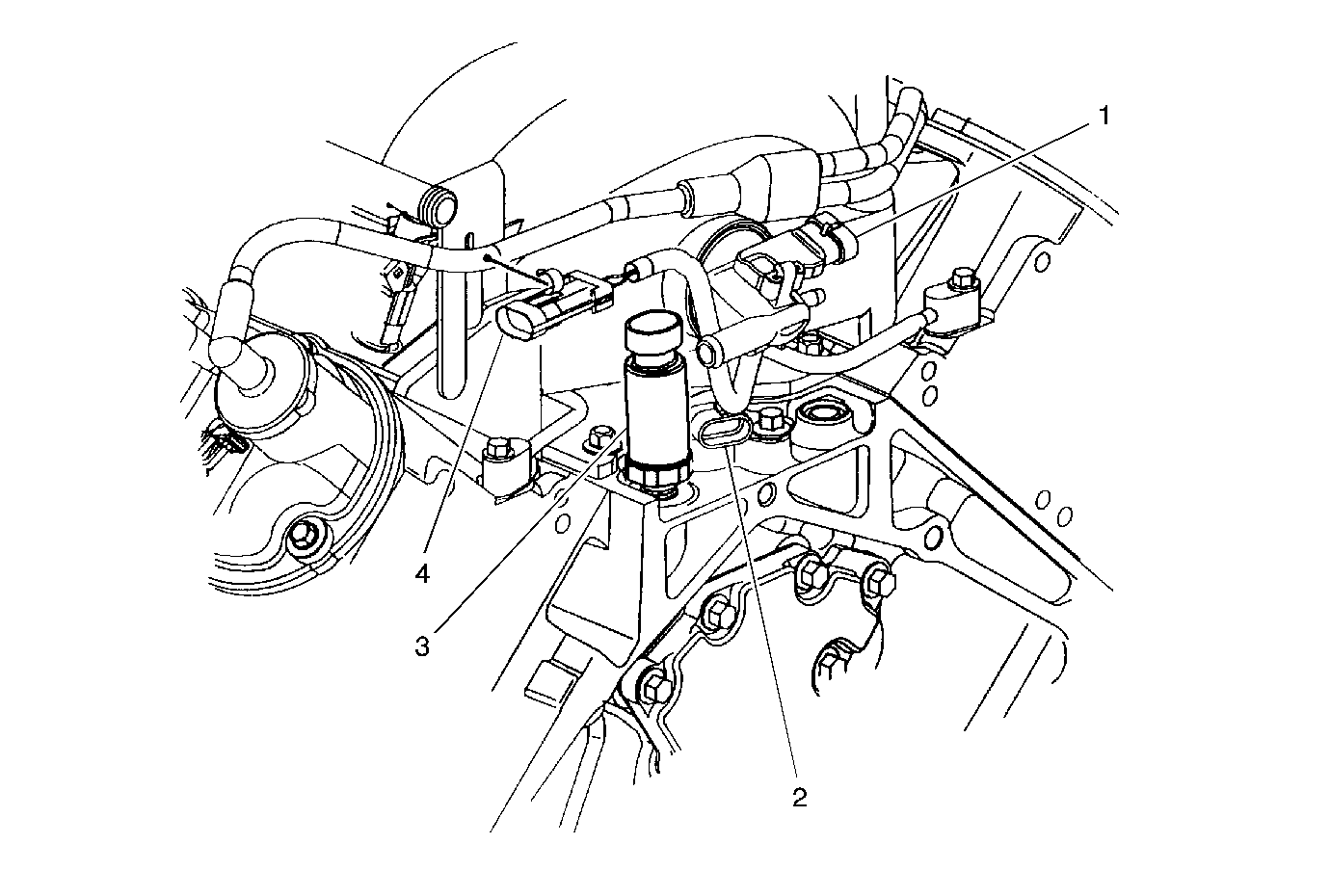
| Figure 4: |
Manifold Absolute Pressure (MAP) Sensor, Camshaft Position (CMP) Sensor,
Oil Pressure Switch
|
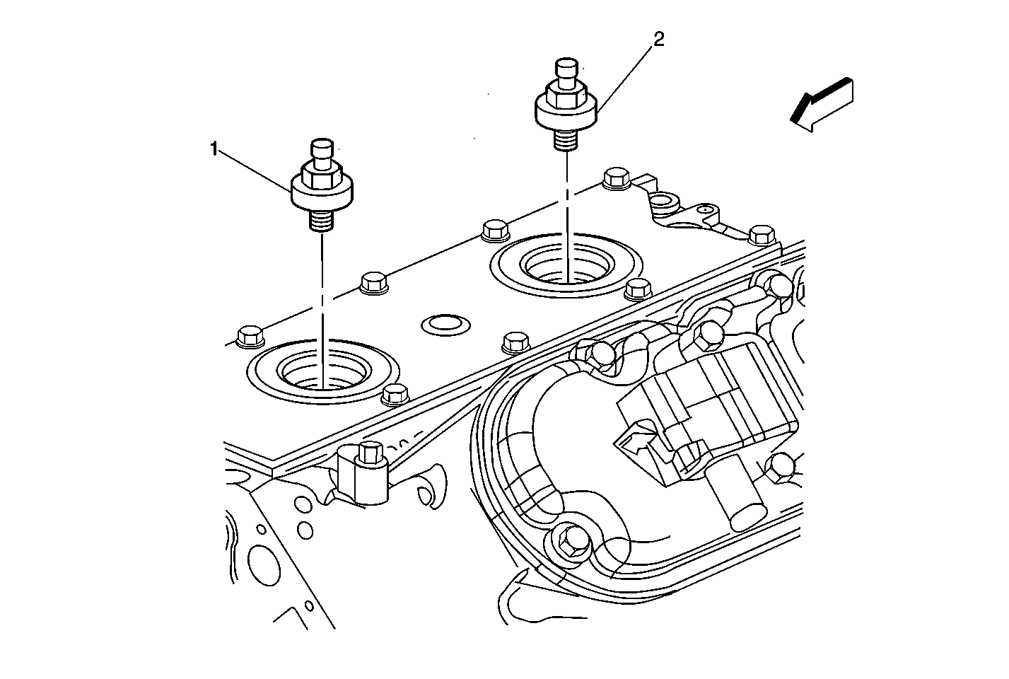
| Figure 5: |
Knock Sensors
|
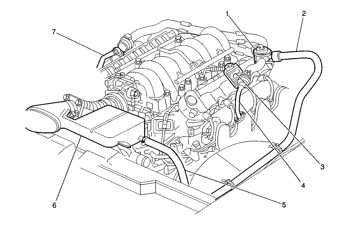
| Figure 6: |
AIR System
|
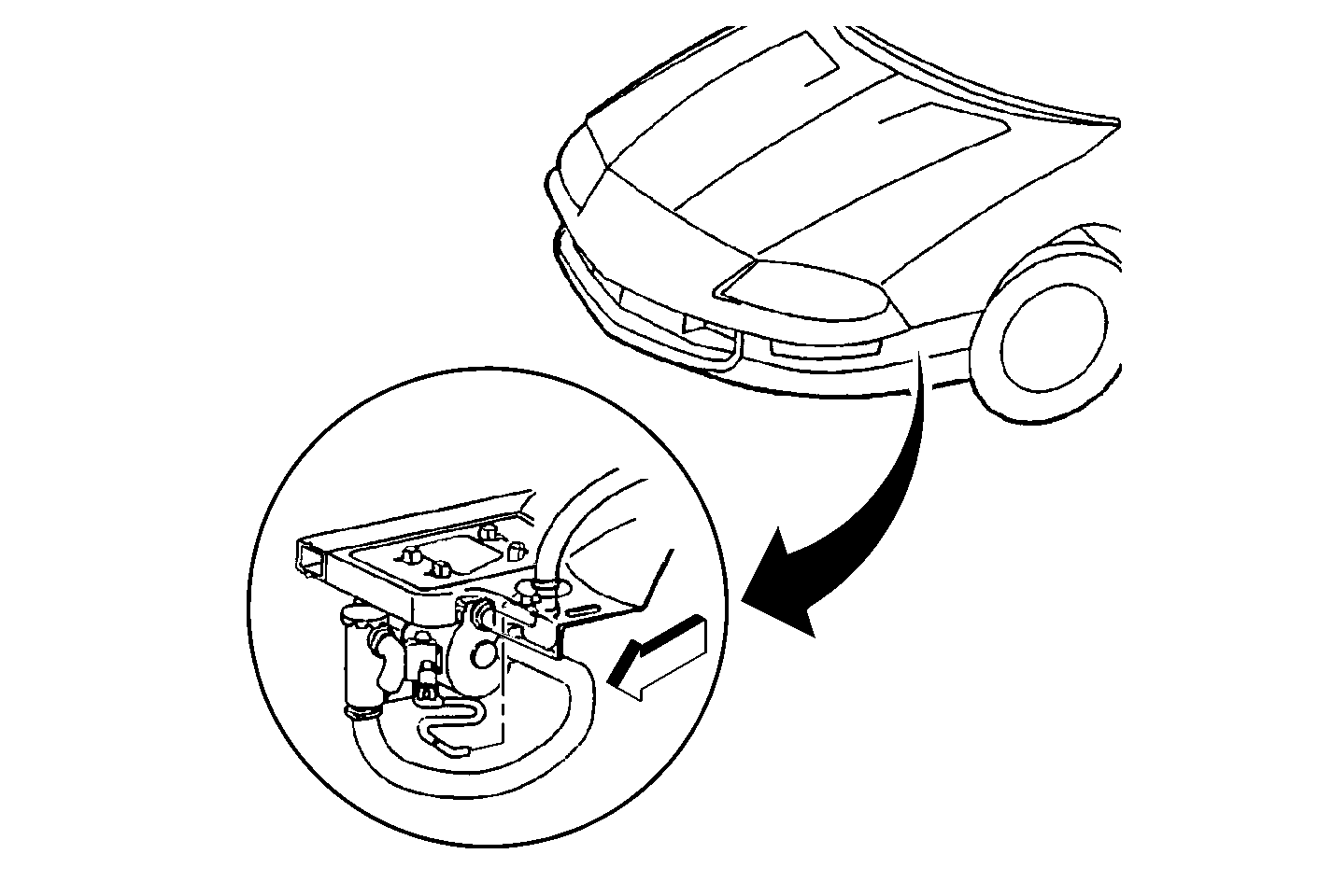
| Figure 7: |
AIR Pump Location
|
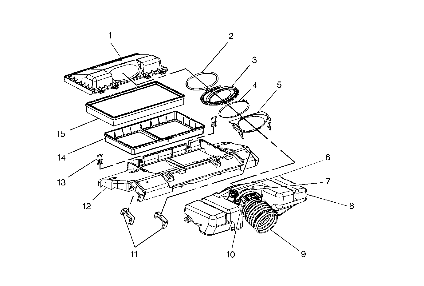
| Figure 8: |
Air Cleaner Housing and Resonator
|
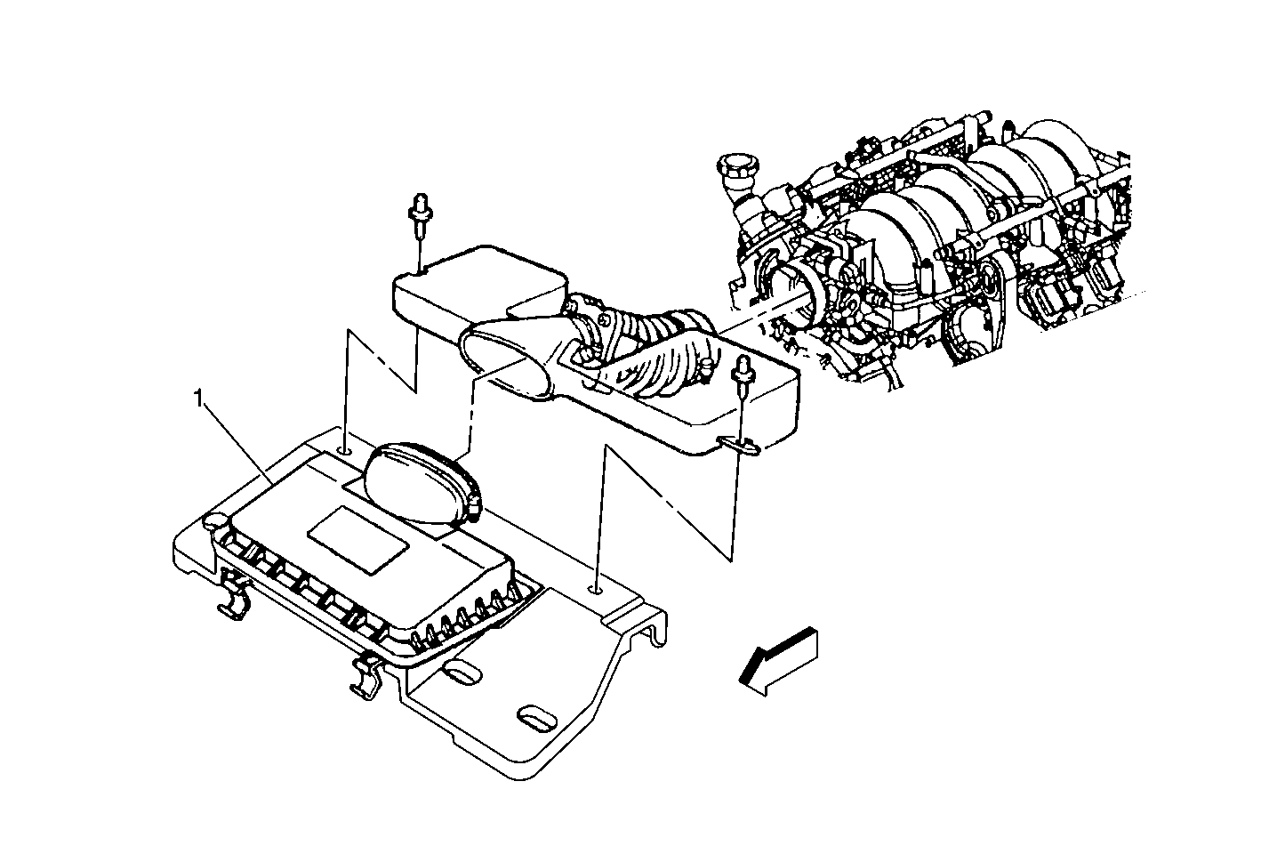
| Figure 9: |
Air Cleaner Location
|
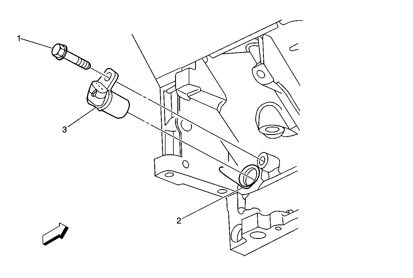
| Figure 10: |
Crankshaft Position Sensor Location
|
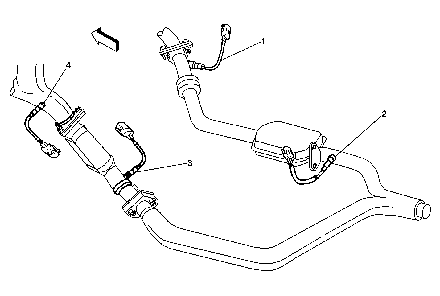
| Figure 11: |
HO2S Location
|
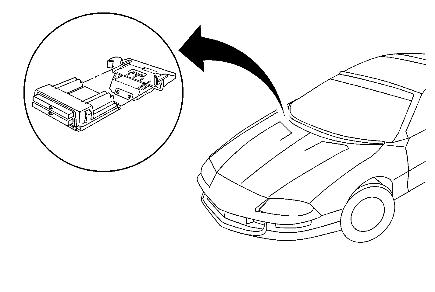
| Figure 12: |
PCM Location
|
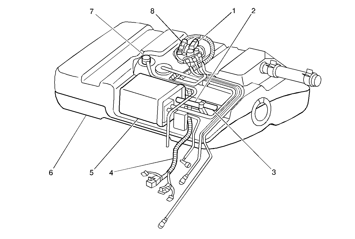
| Figure 13: |
Fuel Tank Assembly with EVAP Canister
|
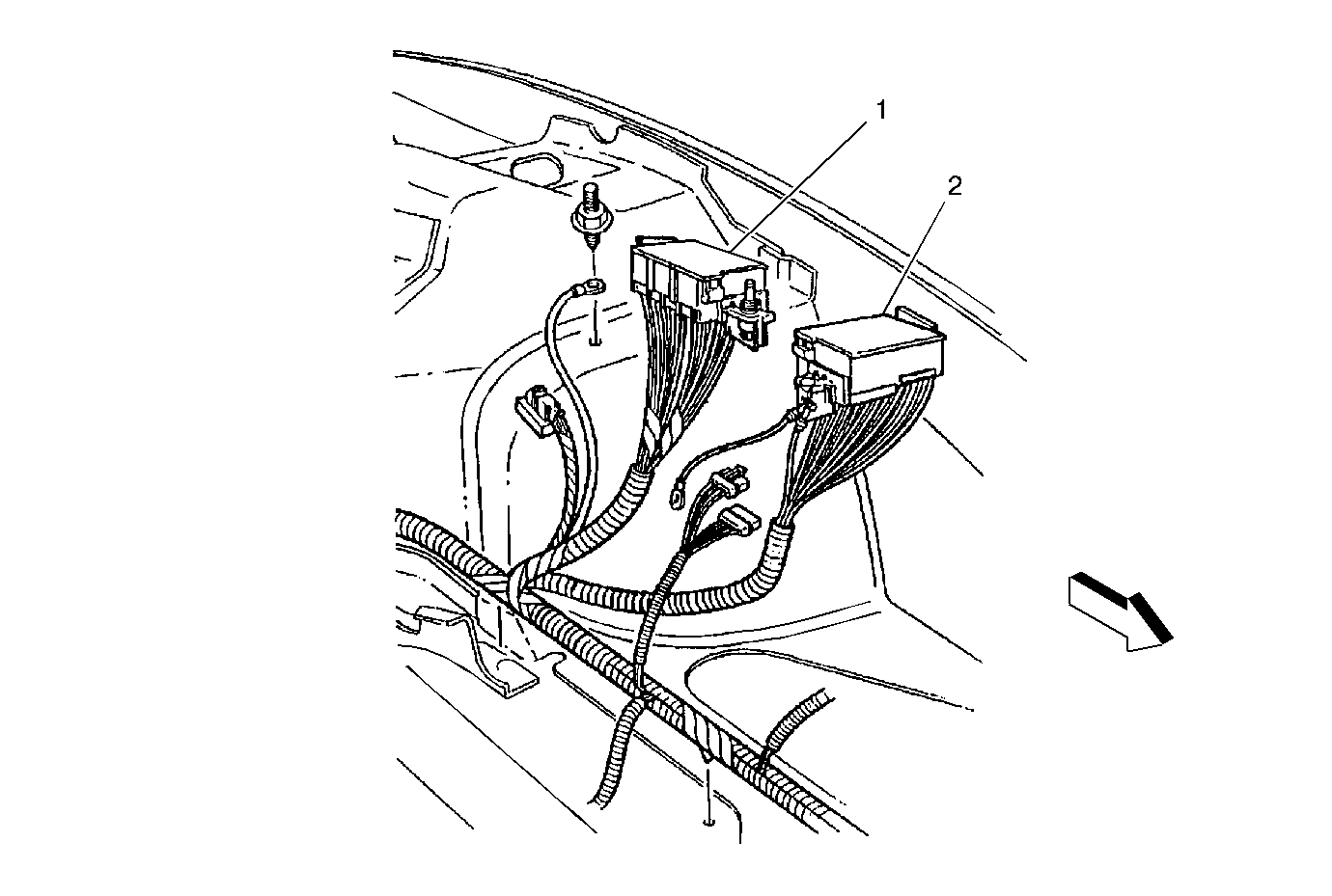
| Figure 14: |
Fuse Blocks #1 and #2
|


