Battery Electrical Drain/Parasitic Load Test for Pontiac Firebird 2001
Tools Required
J 38758 Parasitic Draw Test Switch
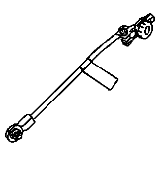
Notice: Do not turn the parasitic draw test switch to the OFF position with the engine running. Damage will occur to the vehicle's electrical system.
Notice: The test switch must be in the ON position when removing the fuses in order to maintain continuity in the electrical system. This avoids damaging the digital multimeter due to accidental overloading, such as a door being opened to change a fuse.
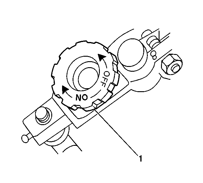
- Disconnect the battery negative cable from the battery negative terminal.
- Install the male end of the J 38758 to the battery negative terminal.
- Turn the J 38758 knob to the OFF position.
- Install the battery negative cable to the female end of the J 38758 .
- Turn the J 38758 knob to the ON position.
- Road test the vehicle and activate all of the accessories, including the radio and the air conditioning.
- Turn OFF all accessories including courtesy lamps.
- Park the vehicle. Turn the ignition switch to the OFF position and remove the ignition key.
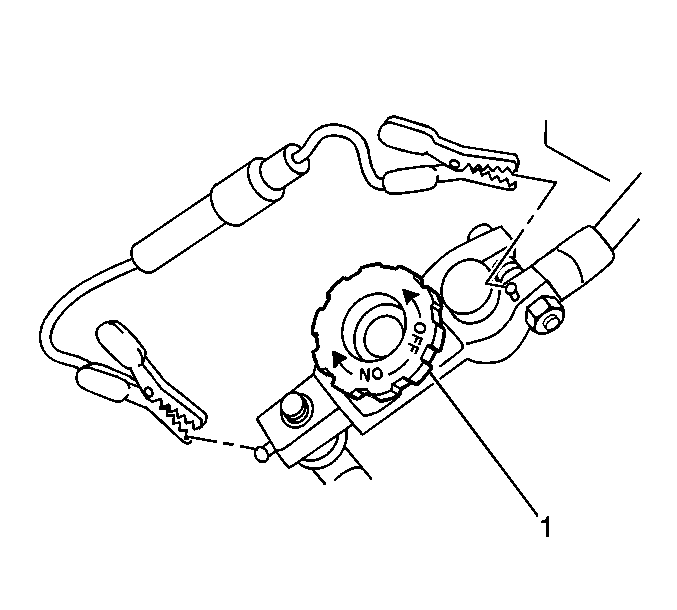
- Connect a 10 A fused jumper wire to the test switch tool terminals.
- Turn the J 38758 knob (1) to the OFF position. The current flows through the jumper wire.
- Wait one minute. If the fuse blows, use an inductive ammeter to locate the current draw.
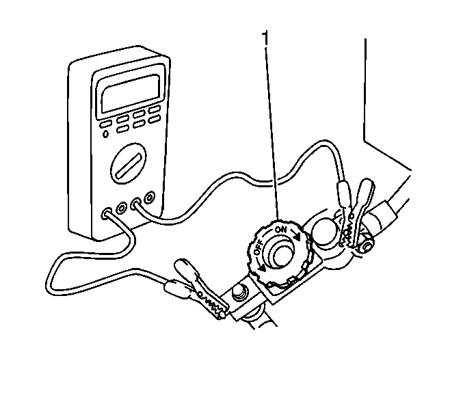
- Set a digital multimeter to the 10 A scale.
- Connect the digital multimeter to the test switch tool terminals.
- Turn the J 38758 knob (1) to the OFF position.
- Wait one minute. Check and record the current reading.
- Turn the J 38758 knob to the OFF position. Wait 10 minutes.
- Check and record the current reading.
- Note the battery reserve capacity. Refer to Battery Usage .
- Check the charging system. If the vehicle has an acceptable amount of current drain, refer to Charging System Test .
- When the vehicle has an unacceptable amount of parasitic current drain, remove each fuse one at a time until the current drain falls to an acceptable level. This will indicate which circuit is causing the drain. Refer to Power Distribution Schematics in Wiring Systems to diagnose exactly which part of the suspect circuit is causing the parasitic drain. In some cases a non-fused circuit or component, such as a generator, is the cause of excessive parasitic current drain.
- Repeat the parasitic current drain test procedure after any repair has been completed to make sure that the parasitic current drain is now at an acceptable level.
- When the cause of the excessive current draw has been located and repaired, remove the J 38758 .
- Connect the battery negative cable to the battery negative terminal. Refer to Fastener Tightening Specifications .
Caution: Refer to Battery Disconnect Caution in the Preface section.
Important: The switch knob (1) on the J 38758 is marked ON and OFF. When the switch knob is in the ON position, the circuit is closed and electrical current will pass through the switch. When the switch knob is in the OFF position, the circuit is open and electrical current will not pass through the switch.
| • | When there is a current reading of 2 A or less, turn the J 38758 knob to the ON position. The electrical current will now pass through the switch. |
| • | Then, switch the digital multimeter to the 2 A scale for a more accurate reading. |
| • | Divide the reserve capacity by 4. |
| • | Compare this to the multimeter milliampere reading taken in the previous step. |
| • | The parasitic current drain should not exceed this number. |
| • | Example: If a battery has a reserve capacity of 100 minutes, the current drain should not exceed 25 mA. |
Notice: The test switch must be in the ON position when removing the fuses in order to maintain continuity in the electrical system. This avoids damaging the digital multimeter due to accidental overloading, such as a door being opened to change a fuse.
Notice: Use the correct fastener in the correct location. Replacement fasteners must be the correct part number for that application. Fasteners requiring replacement or fasteners requiring the use of thread locking compound or sealant are identified in the service procedure. Do not use paints, lubricants, or corrosion inhibitors on fasteners or fastener joint surfaces unless specified. These coatings affect fastener torque and joint clamping force and may damage the fastener. Use the correct tightening sequence and specifications when installing fasteners in order to avoid damage to parts and systems.
