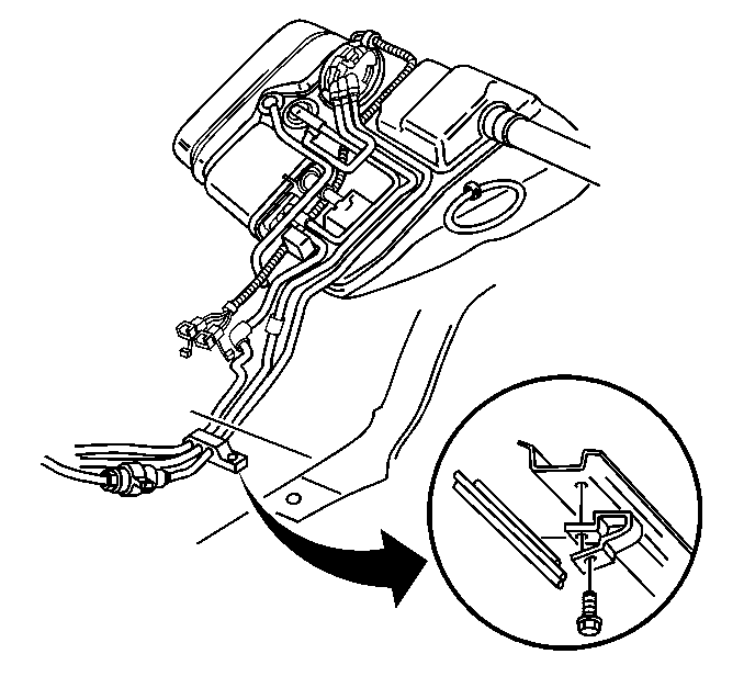
Evaporative Emission System Hoses/Pipes Replacement Engine Compartment
Engine Compartment EVAP Pipe Removal Procedure
- Clean all the EVAP pipe connections and the surrounding areas before disconnecting in order to avoid possible contamination of the EVAP system.
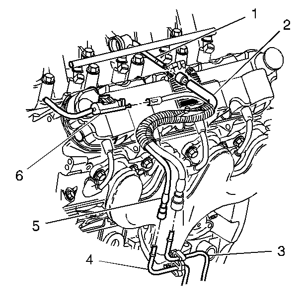
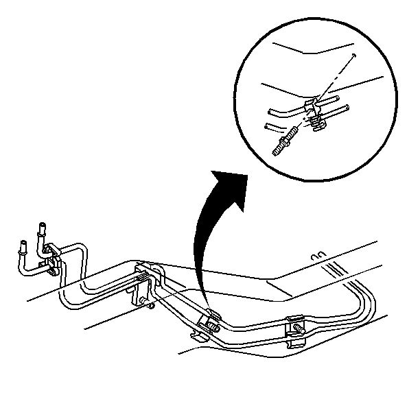
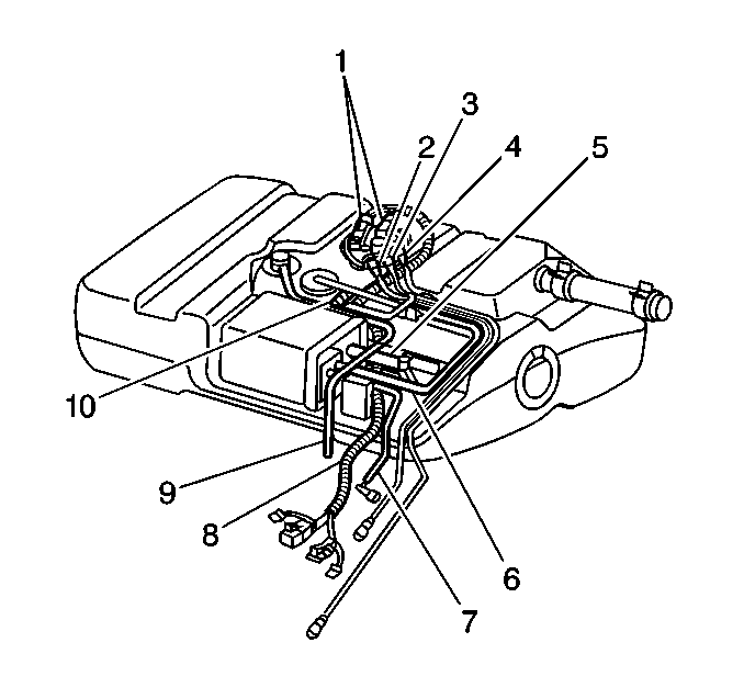
- Disconnect the engine compartment EVAP pipe (5) at the EVAP canister purge valve (6).
- Disconnect the engine compartment EVAP pipe (5) at the chassis EVAP pipe (4).
- Cap the EVAP pipes in order to prevent possible EVAP system contamination.
Engine Compartment EVAP Pipe Installation Procedure
- Remove the caps from the EVAP pipes.
- Connect the engine compartment EVAP pipe (5) to the chassis EVAP pipe (4).
- Connect the engine compartment EVAP pipe (5) to the EVAP canister purge valve (6).
Evaporative Emission System Hoses/Pipes Replacement Chassis
Chassis EVAP Pipe Removal Procedure
- Clean all the EVAP pipe connections and the surrounding areas before disconnecting the pipes in order to avoid possible contamination of the EVAP system.
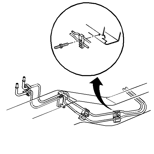
- Disconnect the engine compartment EVAP pipe (5) from the chassis EVAP pipe (4).
- Raise the vehicle. Refer to Lifting and Jacking the Vehicle in General Information.
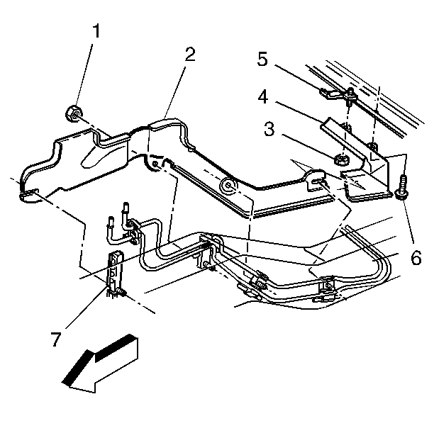
- Remove the rear fuel pipe shield attaching nuts (3) and bolt (6).
- Remove the rear fuel pipe shield (4).
- Remove the front fuel pipe shield attaching nuts (1).
- Remove the front fuel pipe shield (2).
- Disconnect the EVAP purge pipe (1) at the rear quick connect fitting.
- Remove the EVAP pipe attaching hardware and the EVAP pipe. Note the position of the pipe for installation.
Chassis EVAP Pipe Installation Procedure
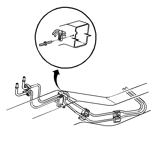
- Position the EVAP pipe to the frame rail.
- Loosely install the clip stud in the indicated position.
- Loosely install the clip stud in the indicated position.
- Loosely install the clip stud in the indicated position.
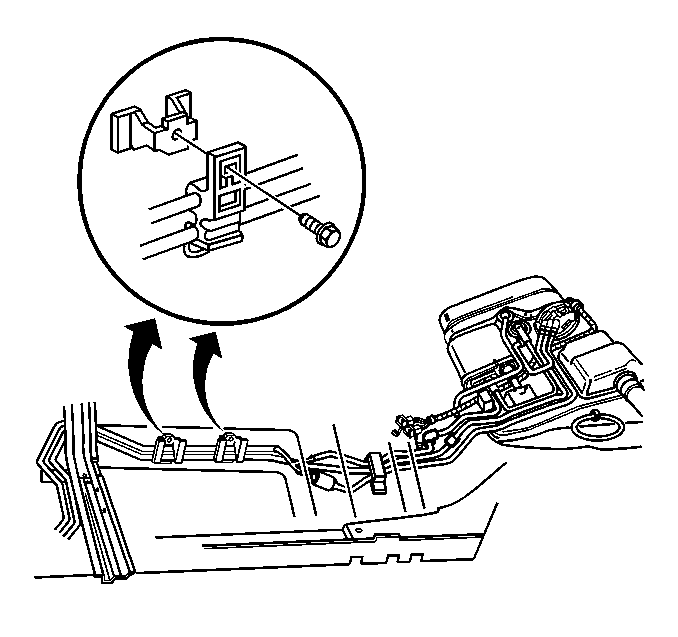
- Align the EVAP pipe clips to the indicated positions.
- Install the front pipe clip bolts.
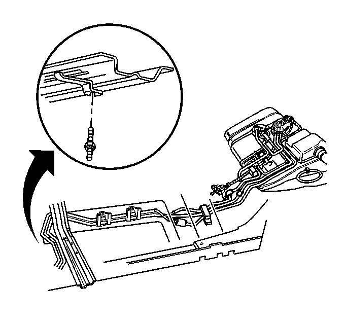
- Align the EVAP pipe clip to the indicated position.
- Install the pipe clamp stud.
- Connect the EVAP purge pipe (1) at the rear quick connect fitting.
- Install the EVAP pipe into the rear pipe clip.
- Align the fuel and EVAP pipes in a flat position.
- Install the rear pipe clip bolt.
- Position the front fuel pipe shield (2) to the 3 fuel pipe clip studs and the brake pipe clip stud (7).
- Install the pipe shield nuts (1).
- Position the rear fuel pipe shield (4) to the fuel pipe stud and the fuel pipe clip stud (5).
- Loosely install the pipe shield nuts (3).
- Install the pipe shield bolt (6).
- Tighten the fuel pipe shield bolt to 5 N·m (44 lb in).
- Tighten the fuel pipe shield nuts to 5 N·m (44 lb in).
- Lower the vehicle.
- Connect the engine compartment EVAP pipe (5) to the chassis EVAP pipe (4).
Important: When replacing the EVAP pipes, always replace them with original equipment or parts that meet the GM specifications for those parts. The replacement pipes must have the same type of fittings as the original pipes in order to ensure the integrity of the connection.
Notice: Use the correct fastener in the correct location. Replacement fasteners must be the correct part number for that application. Fasteners requiring replacement or fasteners requiring the use of thread locking compound or sealant are identified in the service procedure. Do not use paints, lubricants, or corrosion inhibitors on fasteners or fastener joint surfaces unless specified. These coatings affect fastener torque and joint clamping force and may damage the fastener. Use the correct tightening sequence and specifications when installing fasteners in order to avoid damage to parts and systems.
Tighten
Tighten the 3 studs to 5 N·m (44 lb in).
Tighten
Tighten the front pipe clip bolts to 4.5 N·m (40 lb
in).
Tighten
Tighten the pipe clamp stud to 5 N·m (44 lb in).
Tighten
Tighten the rear pipe clip bolt to 5.5 N·m (49 lb
in).
Tighten
Tighten the pipe shield nuts to 5 N·m (44 lb in).
Tighten
Evaporative Emission System Hoses/Pipes Replacement Rear
Rear EVAP Pipes and Hose Removal Procedure
- Remove the fuel tank. Refer to Fuel Tank Replacement .
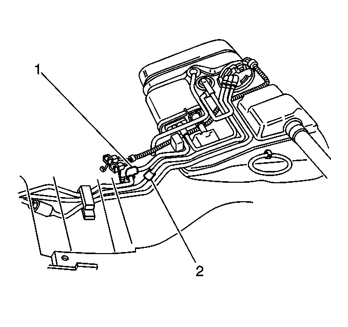
- Remove the EVAP purge pipe (7) from the EVAP canister.
- Remove the EVAP canister vent solenoid hose (5).
- Remove the EVAP pipe to fill limiter vent valve pipe (3).
- Cap the EVAP pipes in order to prevent possible EVAP system contamination.
Rear EVAP Pipes and Hose Installation Procedure
- Remove the caps from the fuel and EVAP pipes.
- Install the EVAP pipe to fill limiter vent valve pipe (3).
- Install the EVAP canister vent solenoid hose (5).
- Connect the EVAP purge pipe (7) to the EVAP canister.
- Install the fuel tank. Refer to Fuel Tank Replacement .
