Tools Required
J 39446 ABS Exciter Ring Protector Kit
Removal Procedure
- Raise and support the vehicle. Refer to Lifting and Jacking the Vehicle in General Information.
- Remove the rear tire and wheel assembly. Refer to Tire and Wheel Removal and Installation in Tires and Wheels.
- Remove the rear brake rotor. Refer to Rear Brake Rotor Replacement in Disc Brakes.
- Remove the rear axle housing cover. Refer to Rear Axle Housing Cover and Gasket Replacement .
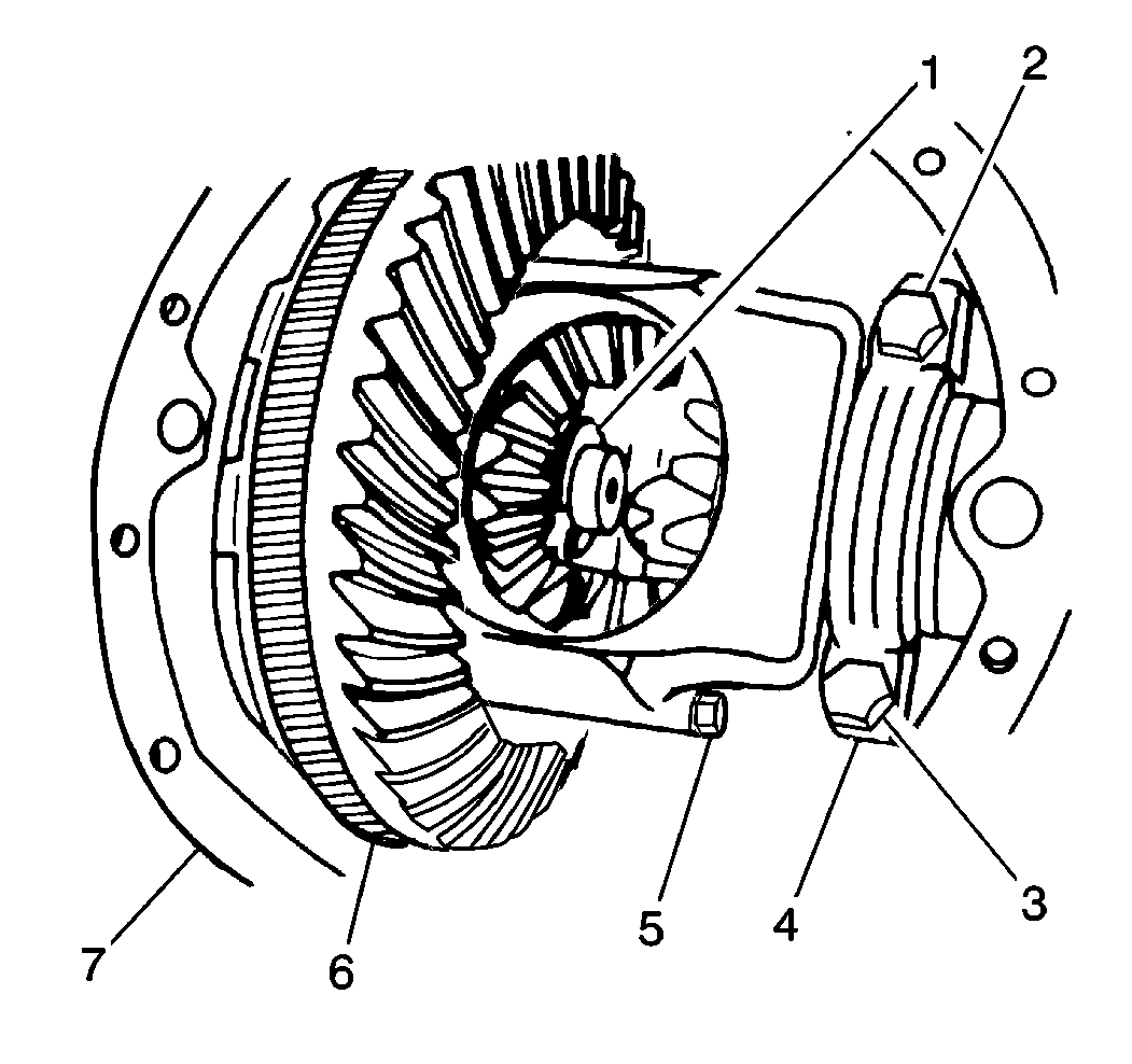
- Install the J 39446 to the speed sensor reluctor wheel (6) on vehicles that are equipped with non-traction control axles.
- Remove the pinion gear shaft lock bolt (5) from the differential case.
- Remove the pinion gear shaft from the differential case.
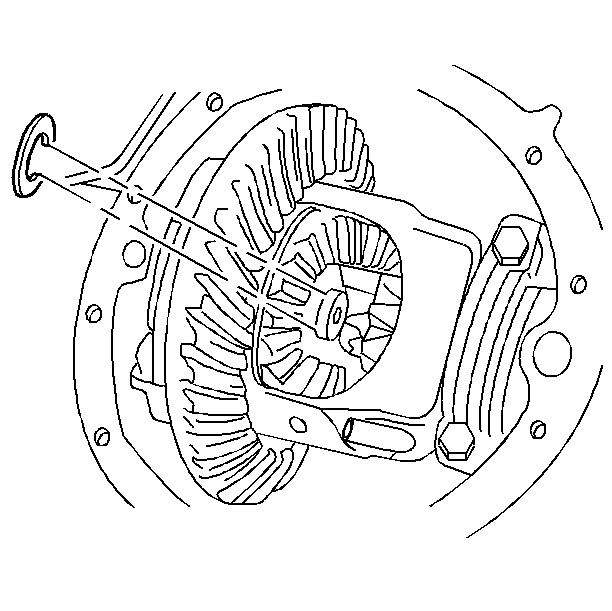
- Push the flanged end of the axle shaft into the rear axle housing in order to access the rear axle shaft lock.
- Remove the rear axle shaft lock.
- Remove the rear axle shaft from the rear axle housing.


Important: Do not damage the rear wheel speed sensor reluctor wheel during axle shaft removal on vehicles that are equipped with traction control.
The rear wheel speed sensor reluctor wheel is located on the axle shaft. If the rear wheel speed sensor reluctor wheel is damaged, replace the rear axle shaft.Installation Procedure
- Install the rear axle shaft to the housing.
- Install the rear axle shaft lock.
- Install the pinion gear shaft through the following components:
- Thoroughly clean the threads of the pinion gear shaft lock bolt (5) and apply threadlocker, GM US P/N 12345382 Canada P/N 10953489 or equivalent to the bolt threads.
- Install the pinion gear shaft lock bolt (5).
- Remove the J 39446 from the speed sensor reluctor wheel (6) if the vehicle has a standard rear axle.
- Install the rear axle housing cover. Refer to Rear Axle Housing Cover and Gasket Replacement .
- Install the rear brake rotor. Refer to Rear Brake Rotor Replacement in Disc Brakes.
- Install the rear tire and wheel assembly. Refer to Tire and Wheel Removal and Installation in Tires and Wheels.
- Lower the vehicle.

Ensure that the following conditions are met:
| • | The splines on the end of the axle shaft do not damage the rear wheel bearing seal. |
| • | The splines on the end of the axle shaft engage with splines of the differential side gear. |
Push the axle shaft outward so that the rear axle shaft lock seats in the counterbore of the differential side gear.
| • | The differential case |
| • | The pinion gear thrust washers |
| • | The pinion gears |
| • | Align the hole in the pinion gear shaft with the rear axle shaft lock bolt/screw hole in the differential case. |

Notice: Use the correct fastener in the correct location. Replacement fasteners must be the correct part number for that application. Fasteners requiring replacement or fasteners requiring the use of thread locking compound or sealant are identified in the service procedure. Do not use paints, lubricants, or corrosion inhibitors on fasteners or fastener joint surfaces unless specified. These coatings affect fastener torque and joint clamping force and may damage the fastener. Use the correct tightening sequence and specifications when installing fasteners in order to avoid damage to parts and systems.
Tighten
Tighten the differential pinion gear shaft lock bolt (5) to 36 N·m
(27 lb ft).
If a new speed sensor reluctor wheel (6) was installed, remove and discard the plastic covering.
