GM Service Manual Online
For 1990-2009 cars only
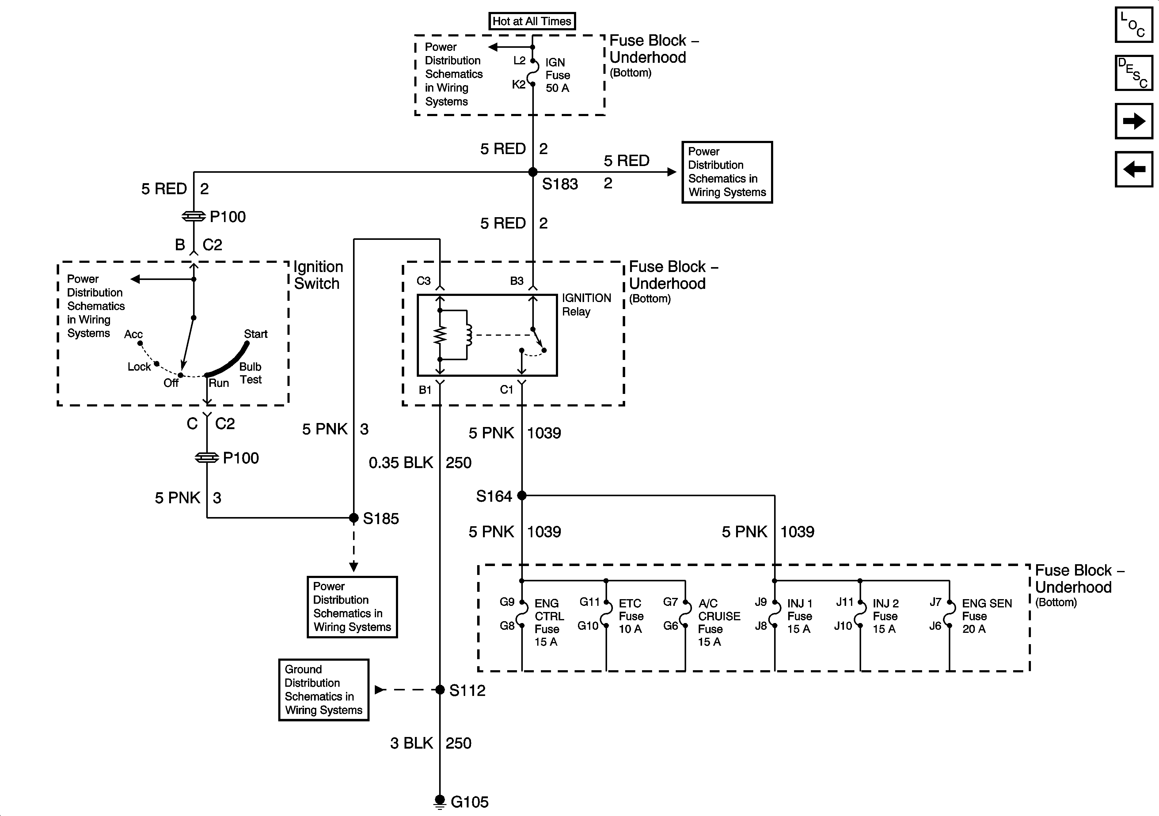
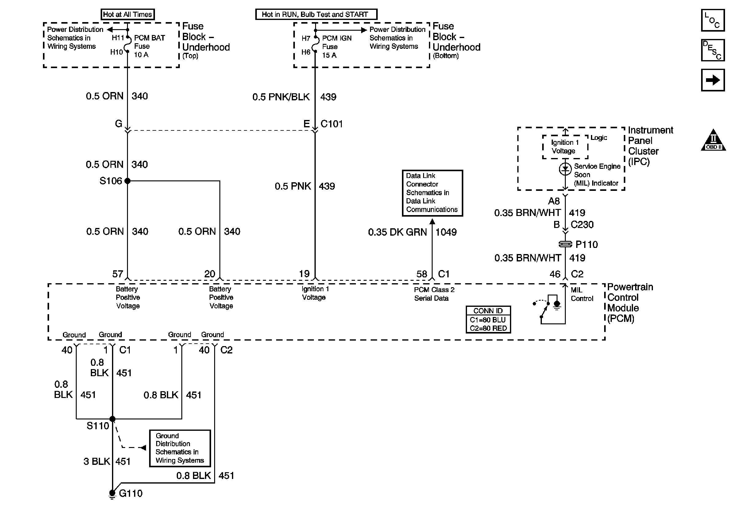
Figure 1:

Module Power, Ground, Serial Data and MIL

Object Number: 771404  Size: FS
Master Electrical Component List
Powertrain Control Module Description
Ignition Relay
OBD II Symbol Description Notice
ENG CTRL, FUEL PUMP, AIR PUMP and PCM BAT Fuses
ABS IGN, PCM IGN and STRTR Fuses
Class 2 Serial Data Communication
G110 V8 LS1
Figure 2:

Ignition Relay


Object Number: 1869018  Size: FS
Master Electrical Component List
Powertrain Control Module Description
Engine Data Sensors 5Volt and Low Reference
Module Power,Ground Serial Data and MIL
Battery Positive Voltage Bussing
IGN Fuse and Ignition Switch Bussing
G105
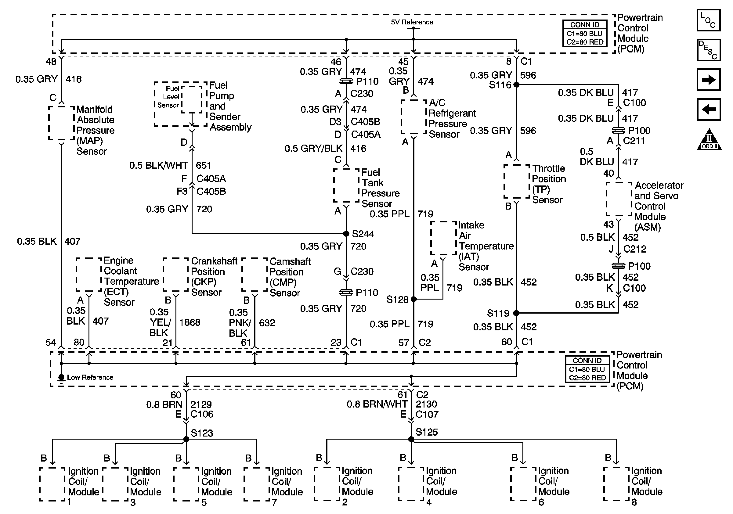
Figure 3:

Engine Data Sensors - 5 Volt and Low Reference

Object Number: 802138  Size: FS
Master Electrical Component List
Powertrain Control Module Description
Engine Data Sensors-Pressure and Temperature
Ignition Relay
OBD II Symbol Description Notice
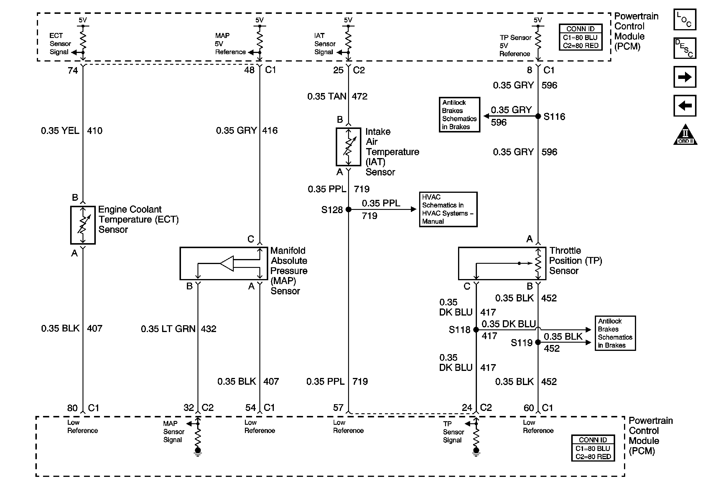
Figure 4:

Engine Data Sensors Pressure and Temperature

Object Number: 771575  Size: FS
Master Electrical Component List
Air Intake System Description
Engine Data Sensors MAF and VSS
Engine Data Sensors 5Volt and Low Reference
OBD II Symbol Description Notice
Traction Control Switch V8 LS1
Compressor Controls - V8 LS1
Traction Control Switch V8 LS1
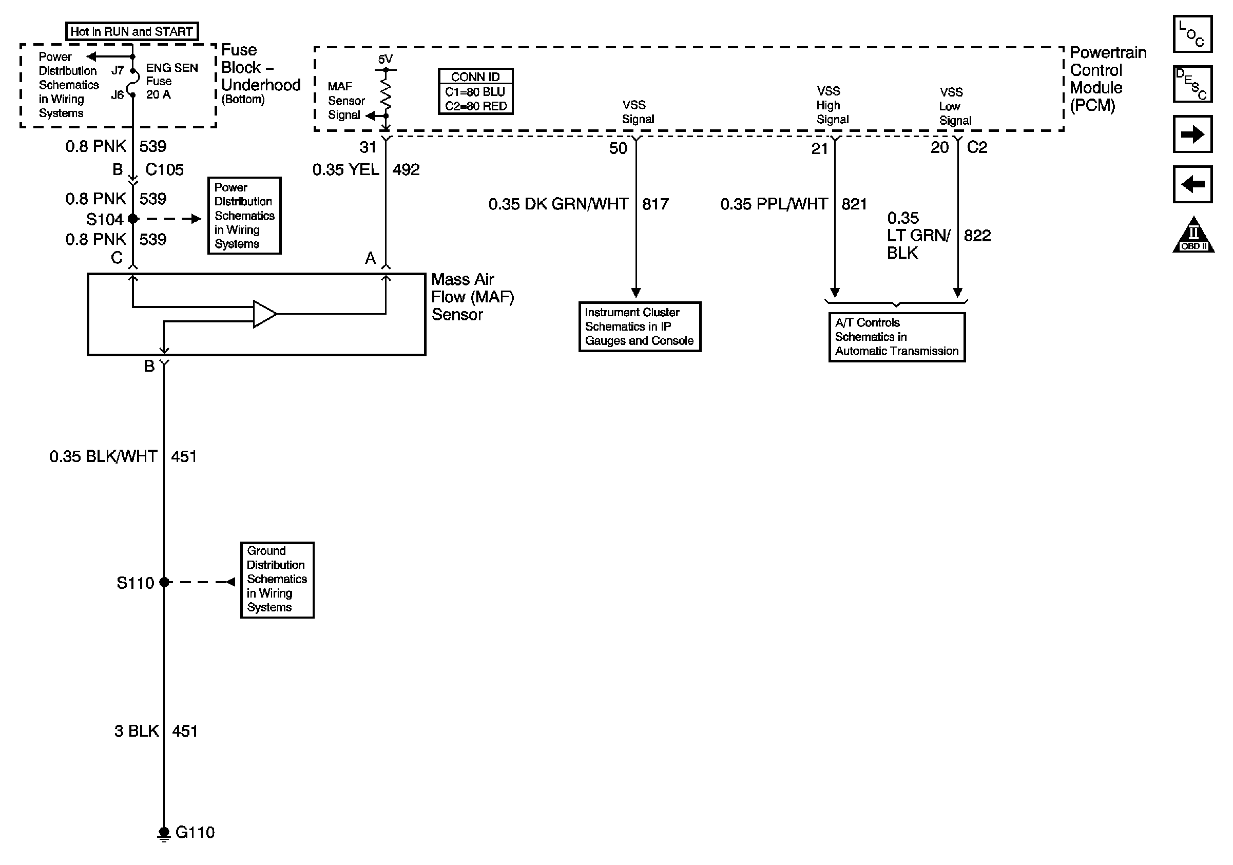
Figure 5:

Engine Data Sensors MAF and VSS


Object Number: 771583  Size: FS
Master Electrical Component List
Evaporative Emission Control System Description
Engine Data Sensors-HO2S
Engine Data Sensors-Pressure and Temperature
OBD II Symbol Description Notice
ENG SEN Fuse
ENG SEN Fuse
Power, Ground, SerialData, Speedometer,Tachometer and Voltmeter
VSS, TFT and PNP V8 LS1
ENG CTRL Fuse
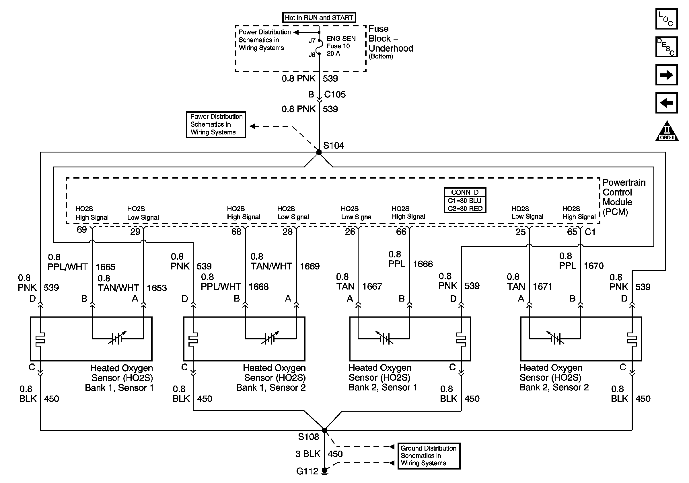
Figure 6:

Engine Data Sensors H02S


Object Number: 771577  Size: FS
Master Electrical Component List
Powertrain Control Module Description
Ignition Controls-Ignition System 1,3,5,7
Engine Data Sensors MAF and VSS
OBD II Symbol Description Notice
ENG SEN Fuse
ENG SEN Fuse
G112 V8 LS1
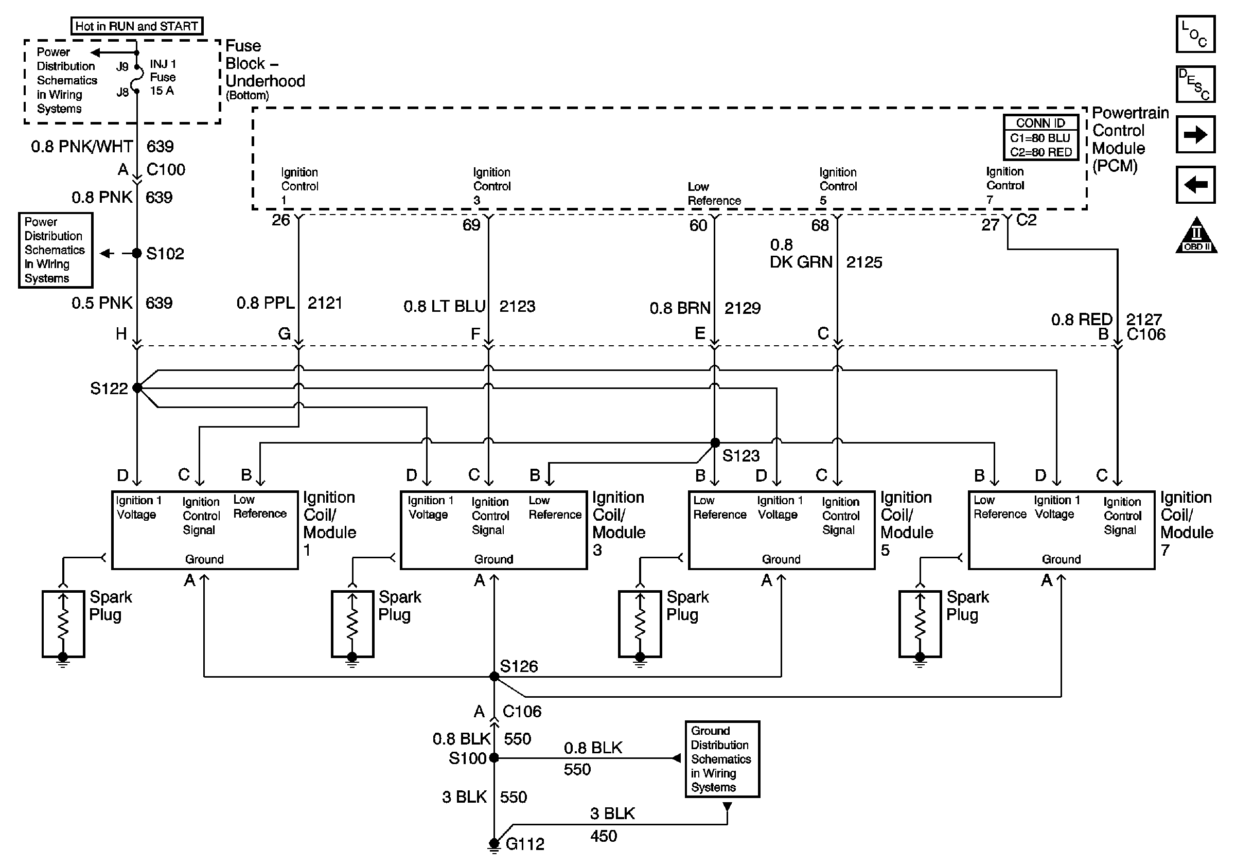
Figure 7:

Ignition Controls Ignition System 1,3,5,7

Object Number: 771454  Size: FS
Master Electrical Component List
Electronic Ignition (EI) System Description
Ignition Controls-Ignition System 2,4,6,8
Engine Data Sensors-HO2S
OBD II Symbol Description Notice
INJ 1 Fuse
INJ 1 Fuse
G112 V8 LS1
Figure 8:

Ignition Controls Ignition System 2,4,6,8
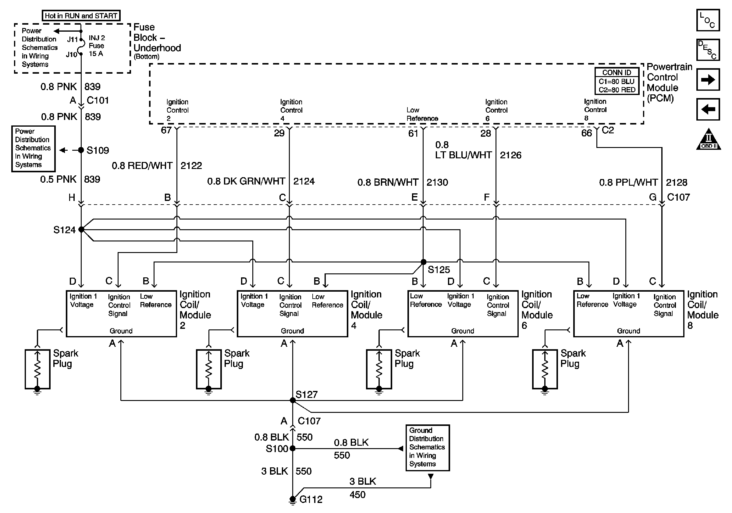

Object Number: 771455  Size: FS
Master Electrical Component List
Electronic Ignition (EI) System Description
Ignition Controls Sensors
Ignition Controls-Ignition System 1,3,5,7
OBD II Symbol Description Notice
INJ 2 Fuse
INJ 2 Fuse
G112 V8 LS1
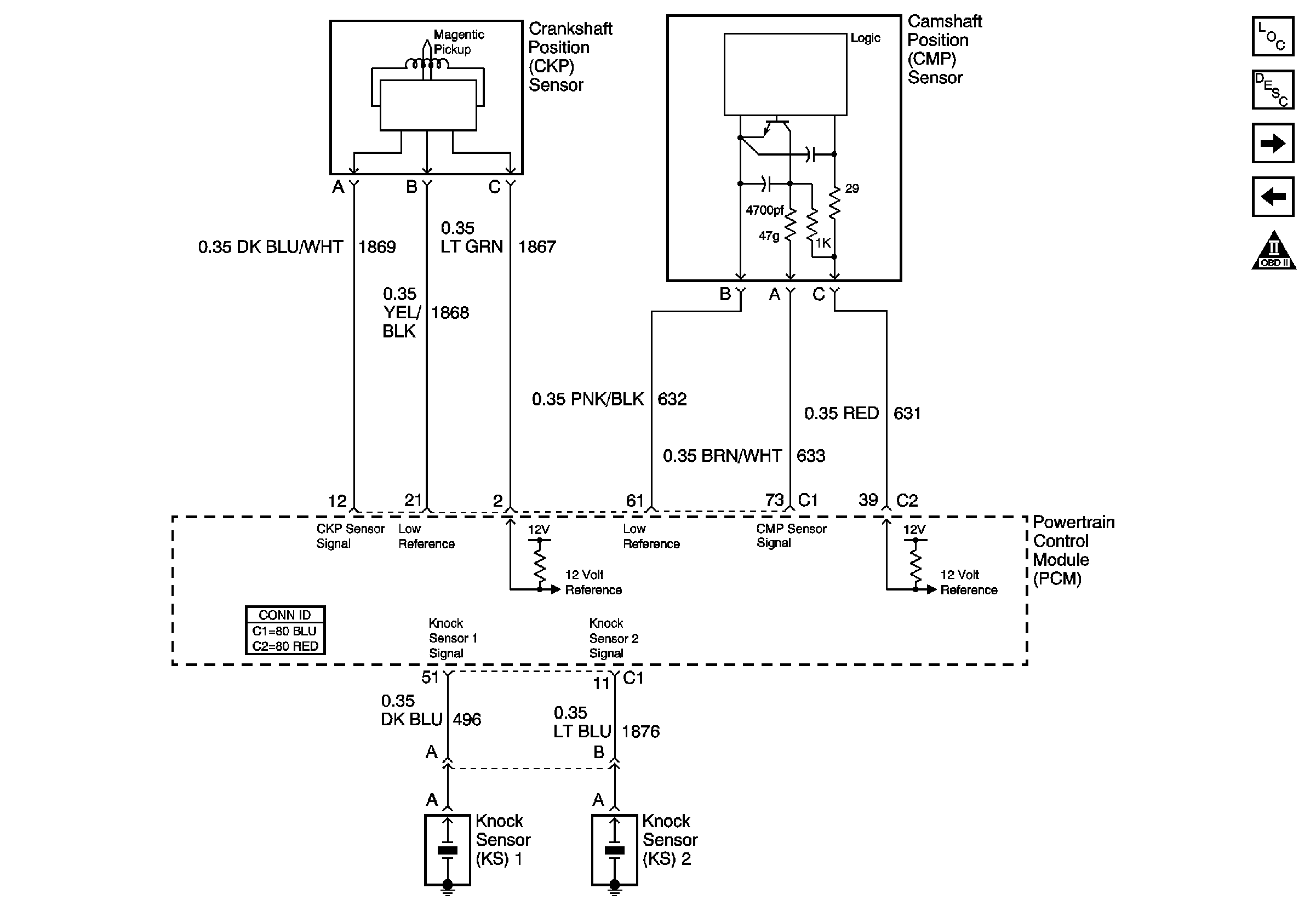
Figure 9:

Ignition Controls Sensors


Object Number: 771457  Size: FS
Master Electrical Component List
Knock Sensor (KS) System Description
Fuel Controls-Fuel Pump Controls
Ignition Controls-Ignition System 2,4,6,8
OBD II Symbol Description Notice
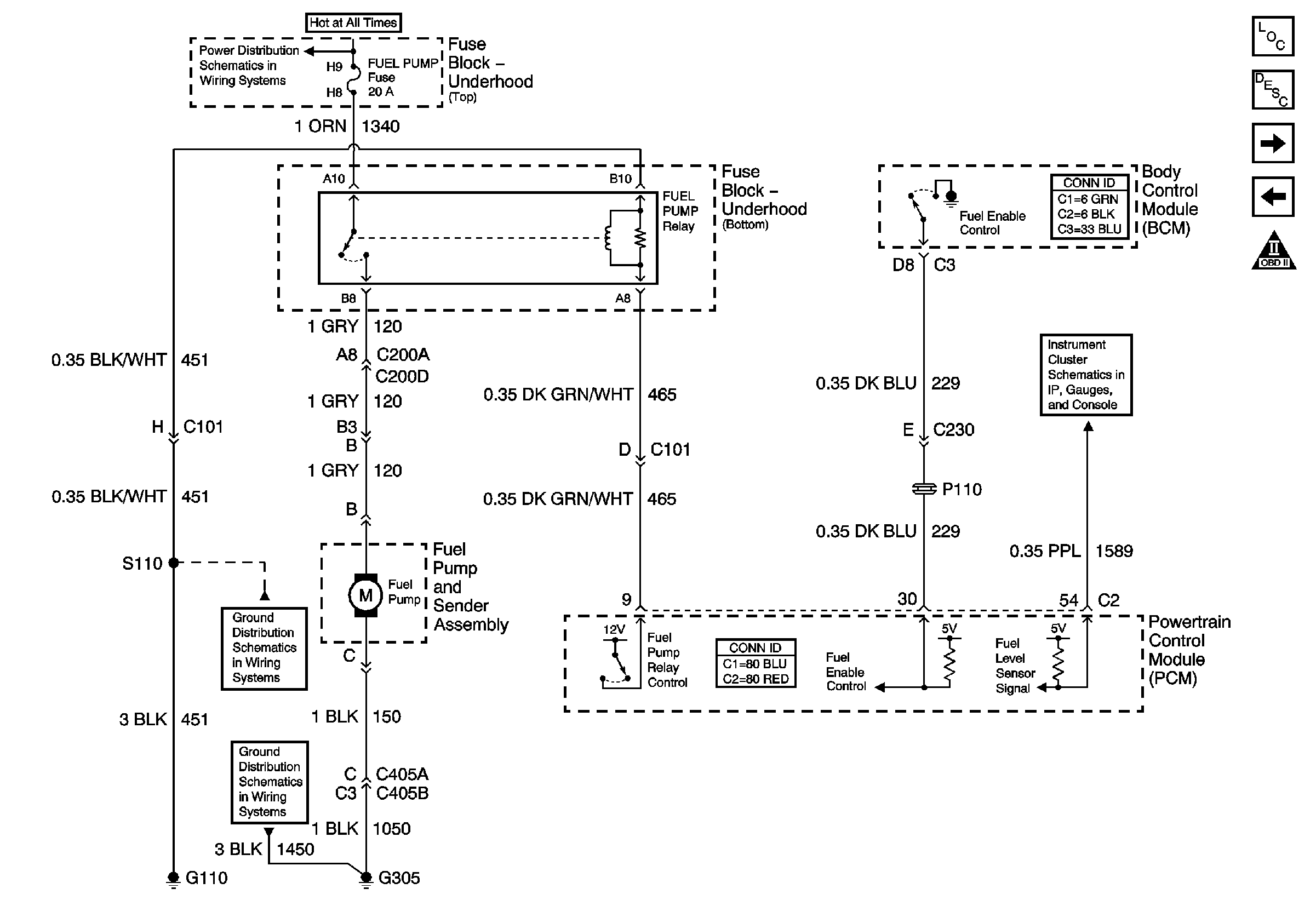
Figure 10:

Fuel Controls Fuel Pump Controls


Object Number: 771459  Size: FS
Master Electrical Component List
Fuel System Description
Fuel Controls-Fuel Injectors
Ignition Controls Sensors
OBD II Symbol Description Notice
ENG CTRL, FUEL PUMP, AIR PUMP and PCM BAT Fuses
G110 V6 L36
G305, G310, G320
Engine Coolant Temperature Gauge, Engine Oil Pressure Gauge and Fuel Level Gauge
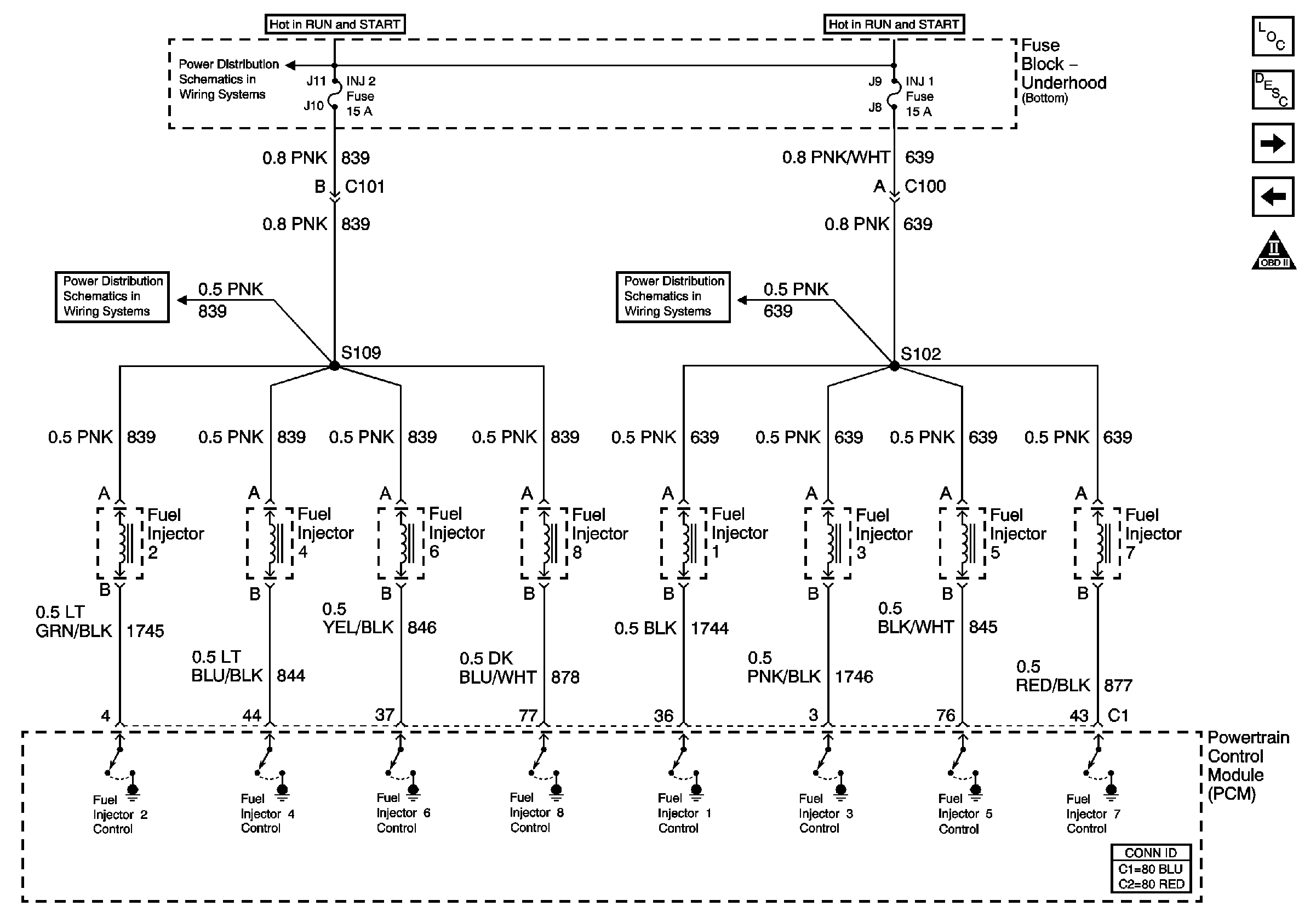
Figure 11:

Fuel Controls Fuel Injectors


Object Number: 771573  Size: FS
Master Electrical Component List
Fuel System Description
Fuel Controls-EVAP Controls
Fuel Controls-Fuel Pump Controls
OBD II Symbol Description Notice
INJ 2 Fuse
INJ 2 Fuse
INJ 1 Fuse
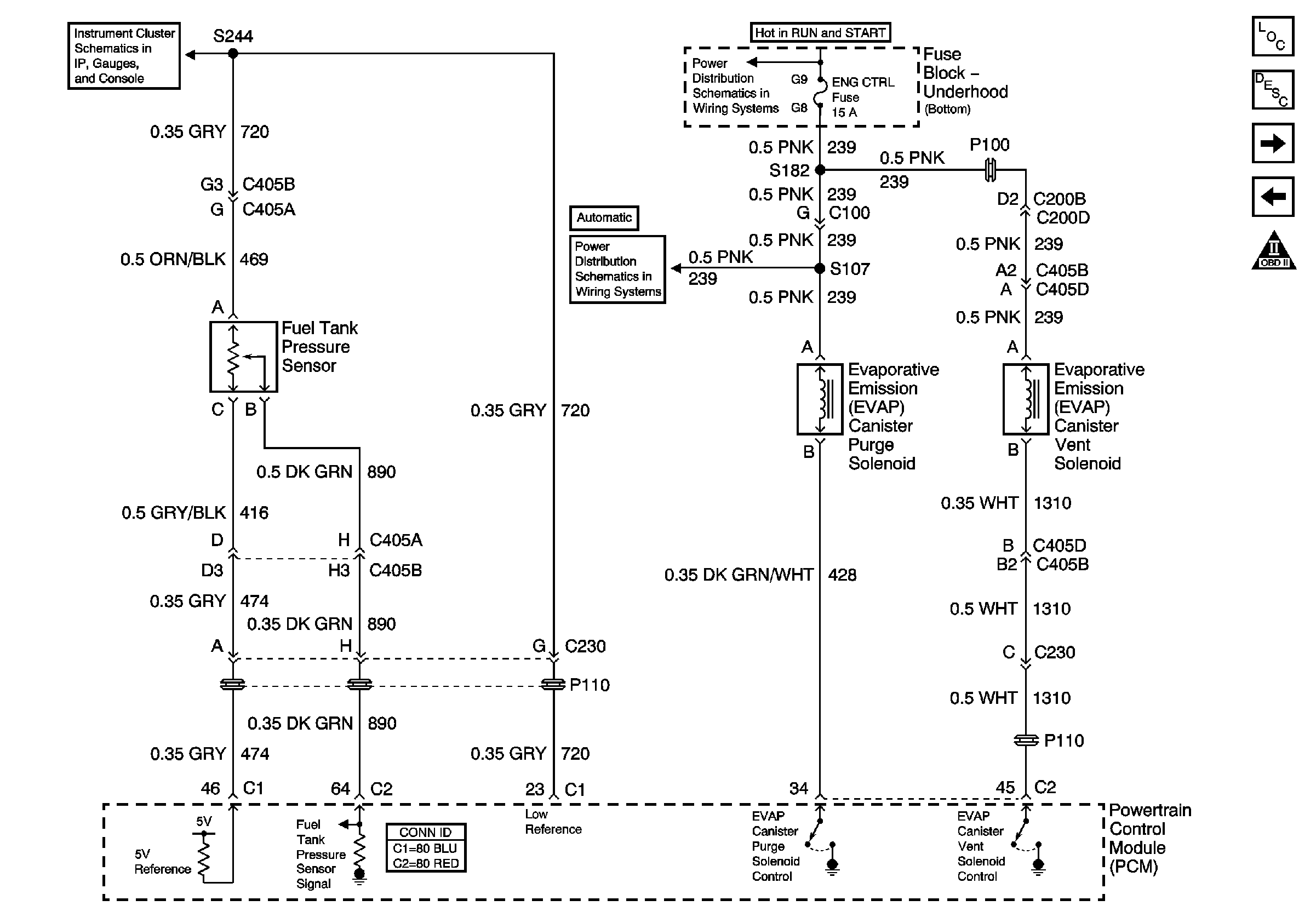
Figure 12:

Fuel Controls EVAP Controls


Object Number: 771462  Size: FS
Master Electrical Component List
Fuel System Description
Device Controls
Fuel Controls-Fuel Injectors
OBD II Symbol Description Notice
Engine Coolant Temperature Gauge, Engine Oil Pressure Gauge and Fuel Level Gauge
ENG CTRL Fuse
ENG CTRL Fuse
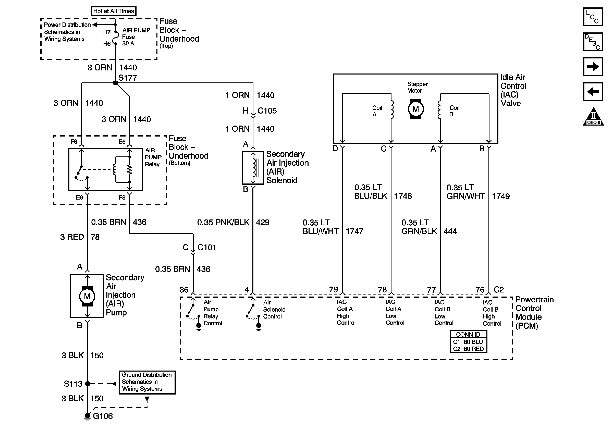
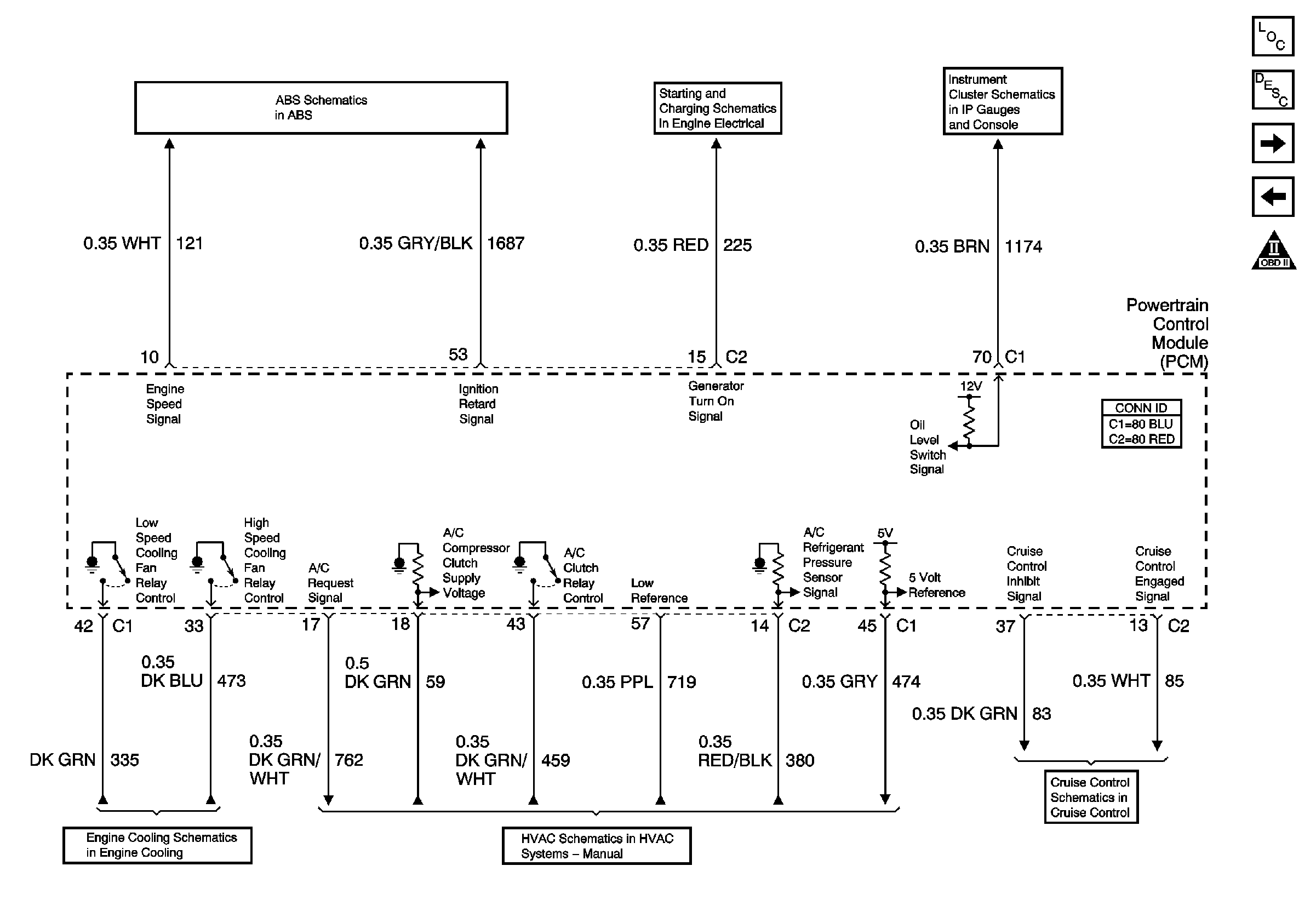
Figure 13:

Device Controls


Object Number: 771580  Size: FS
Master Electrical Component List
Secondary Air Injection System Description
Controlled Monitored Subsystem References
Fuel Controls-EVAP Controls
OBD II Symbol Description Notice
ENG CTRL, FUEL PUMP, AIR PUMP and PCM BAT Fuses
G106
Figure 14:

Controlled Monitored Subsystem References


Object Number: 771584  Size: FS
Master Electrical Component List
Powertrain Control Module Description
Transmission Controls-M/T and A/T
Device Controls
OBD II Symbol Description Notice
Indicators
Charging
ASM,Accelerator Control and Adjuster V8 VIN G W/NW9
V8 VIN G
Compressor Controls - V8 LS1
Release/Inhibit Signals V8 LS1
Figure 15:

Transmission Controls Manual and Automatic
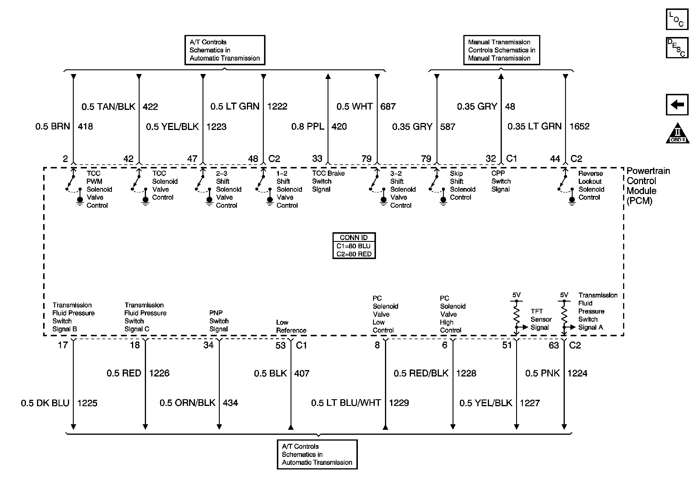

Object Number: 771586  Size: FS
Master Electrical Component List
Powertrain Control Module Description
Controlled Monitored Subsystem References
OBD II Symbol Description Notice
Solenoids and TCC V8 LS1
MM6
VSS, TFT and PNP V8 LS1