Tools Required
J 36221 Hydraulic Clutch Line Separator
Removal Procedure
- Remove the driver side instrument panel insulator. Refer to Instrument Panel Insulator Panel Replacement - Left Side in Instrument Panel, Gages and Console.
- Remove the drive side knee bolster. Refer to Driver Knee Bolster Replacement in Instrument Panel, Gages and Console.
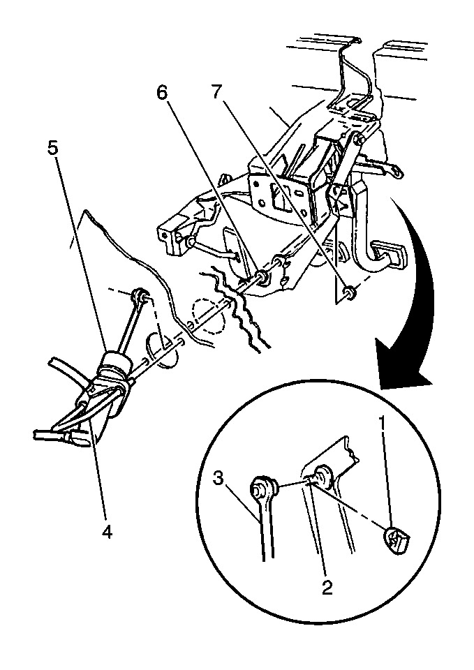
- Remove the clutch pedal pin retainer (1).
- Remove the clutch master cylinder push rod (3) from the clutch pedal pin (2).
- Remove the clutch master cylinder nuts (7).
- Remove the clutch master cylinder push on nuts (6).
- Remove the clutch master cylinder U-bolt (4).
- Remove the clutch master cylinder (5) from the front of dash.
- Raise and suitably support the vehicle. Refer to Lifting and Jacking the Vehicle in General Information.
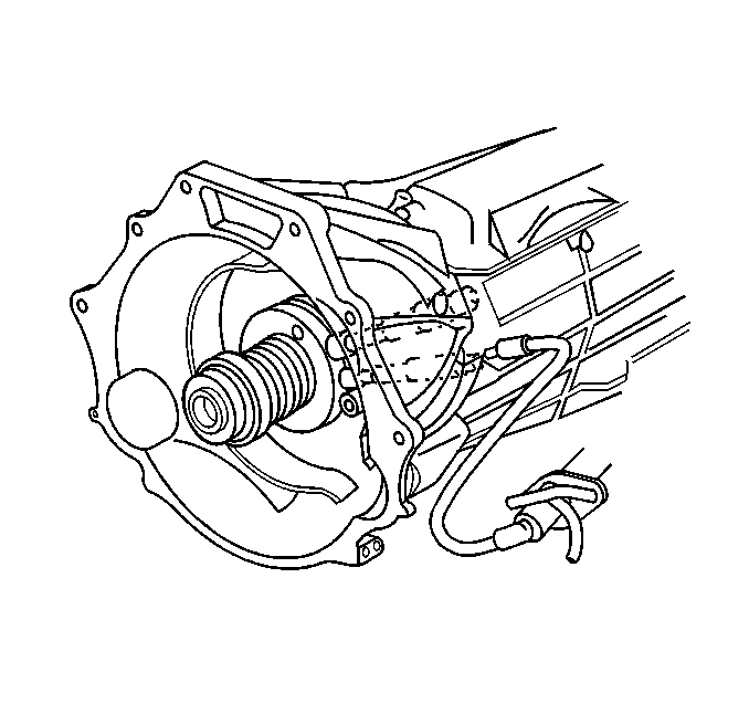
- Using the J 36221 , depress the white circular release ring on the actuator hose and simultaneously pull lightly on the master cylinder hose to disconnect.
- Protect both hose coupling ends from dirt and damage.
- Lower the vehicle.
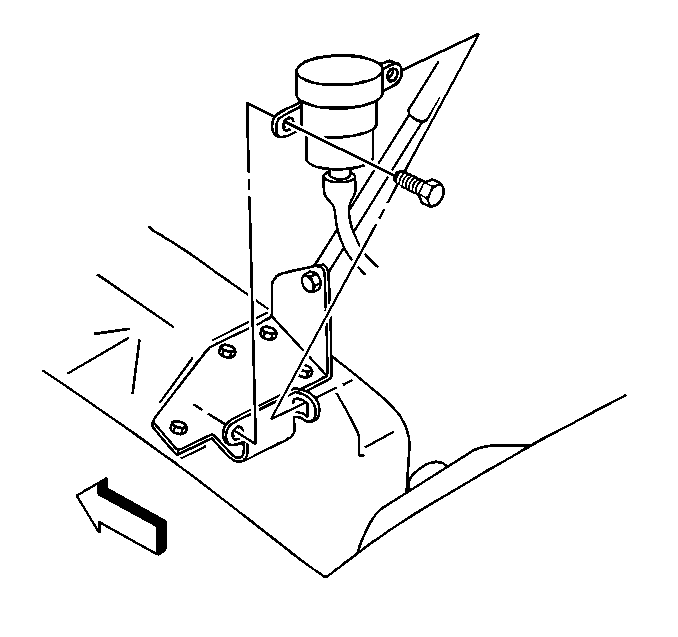
- Remove the clutch master cylinder reservoir push-in retainer.
- Slide the clutch master cylinder reservoir out from the hood strut bracket.
- Remove the clutch master cylinder (and reservoir) from the vehicle.


Installation Procedure
- Install the clutch master cylinder into the opening in the front of dash.
- Slide the clutch master cylinder reservoir into the opening on the hood strut bracket.
- Install the clutch master cylinder reservoir push-in retainer.
- Raise the vehicle.
- Connect the clutch master cylinder hose to the clutch actuator.
- Check the clutch hydraulic hoses for twists or kinks.
- Lower the vehicle.
- Install the clutch master cylinder U-bolt (4).
- Install the clutch master cylinder push on nuts (6).
- Install the clutch master cylinder nuts (7).
- Install the clutch master cylinder push rod (3) onto the clutch pedal pin (2).
- Install the clutch pedal pin retainer (1).
- Remove the drive side knee bolster. Refer to Driver Knee Bolster Replacement in Instrument Panel, Gages and Console.
- Remove the driver side instrument panel insulator. Refer to Instrument Panel Insulator Panel Replacement - Left Side in Instrument Panel, Gages and Console.
- Bleed the clutch hydraulic system. Refer to Hydraulic Clutch Bleeding .


Important: DO NOT rely on an audible click or a visual verification of the clutch hydraulic hose quick connect fitting connection.
Push together the clutch hydraulic quick connect fittings, then pull back on the fittings to verify engagement.

Notice: Use the correct fastener in the correct location. Replacement fasteners must be the correct part number for that application. Fasteners requiring replacement or fasteners requiring the use of thread locking compound or sealant are identified in the service procedure. Do not use paints, lubricants, or corrosion inhibitors on fasteners or fastener joint surfaces unless specified. These coatings affect fastener torque and joint clamping force and may damage the fastener. Use the correct tightening sequence and specifications when installing fasteners in order to avoid damage to parts and systems.
Tighten
Tighten the clutch master cylinder nuts (7) to 20 N·m (15 lb ft).
