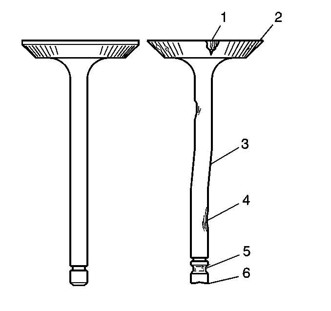
- Inspect the valves for the following conditions:
| • | Burnt or eroded areas (1) |
| • | A worn or scored stem (4) |
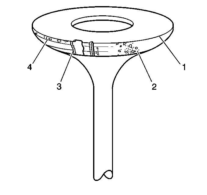
- Inspect the valve face for the following conditions:
| • | Burnt or eroded areas (3) |
- Inspect the valve seats for a loose fit in the cylinder head.
Notice: Proper valve stem-to-valve guide clearance is necessary for proper engine
operation and component life. Excessive clearance may cause a noisy valve
train, premature valve stem oil seal failure, excessive oil consumption and
related component damage. Insufficient clearance may cause a noisy valve train,
rough engine operation or sticking valves that may lead to related component
damage. Failure to inspect valve stem-to-valve guide clearance and repair
or replace necessary components may lead to extensive engine damage.
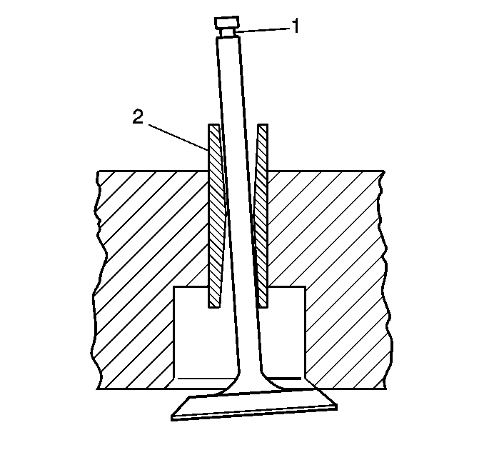
Important: Excessive valve stem-to guide clearance may cause the following conditions:
| • | Premature valve stem oil seal wear |
| • | Excessive engine oil consumption |
- Inspect for excessive valve stem (1) to guide (2) clearance.
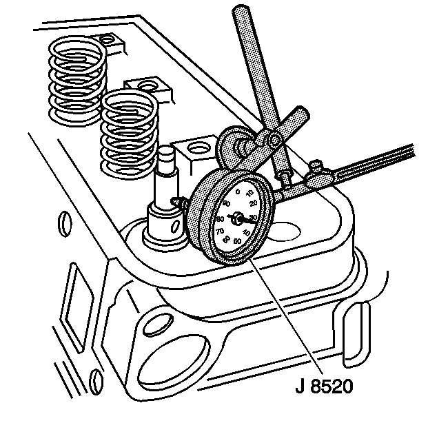
- Use a dial indicator in order to measure the valve stem-to-guide clearance. Complete the following
steps:
| 5.1. | Install the valve into the guide. |
| 5.2. | Install the
J 8520
onto the cylinder head. |
| 5.3. | Locate the dial indicator so that the movement of the valve stem from side to side, crosswise to the cylinder head, will cause a direct movement on the indicator stem. |
| 5.4. | Ensure that the indicator stem contacts the side of the valve stem just above the valve guide. |
| 5.5. | Drop the valve head about 2 mm (1/8 in) off the valve seat. |
| 5.6. | Use light pressure and move the valve stem side to side in order to obtain a clearance reading. |
| 5.7. | If the valve stem to guide clearance is not within specification, replace the valve and/or repair the guide in order to obtain the proper clearances. |
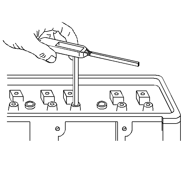
Important: Replace a valve stem that has excessive scoring or wear. A valve guide that is worn and has excessive stem-to-guide clearance may need to be sleeved.
- Ream the valve guides for oversize valves if the clearance exceeds the specifications.
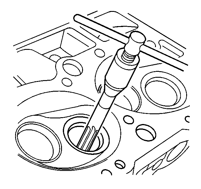
Important: Follow the manufacturers instructions when using valve guide reamers, sleeves, and installers.
- Ream the valve guide in order to obtain the proper specification.
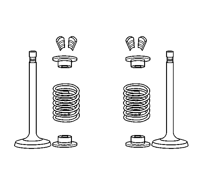
Important: Valves that are pitted must be refaced to the proper angle. Replace valve stems that show excessive wear, or replace valves that are warped. Several different types of equipment are available for refacing
valves and valve seats. Follow the manufacturers recommendations when performing these procedures.
- Inspect the valves for excessive scoring.
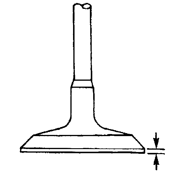
- Inspect the valve face.
Replace the valve if the valve margin is not within specifications after grinding.
- Reface pitted valves on a valve refacing machine in order to ensure the correct relationship between the head and the stem.
Important: Reconditioning the valve seats is very important. Ensure perfect seating of the valves in the engine in order to deliver optimum power and performance. Clean the valve guides of all debris and dirt before grinding
the valve seat.
- Recondition the valve seats after reaming the valve guide bores or installing the new valve guides.
- The valve seats should be concentric to within 0.05 mm (0.031 in) total indicator reading.


