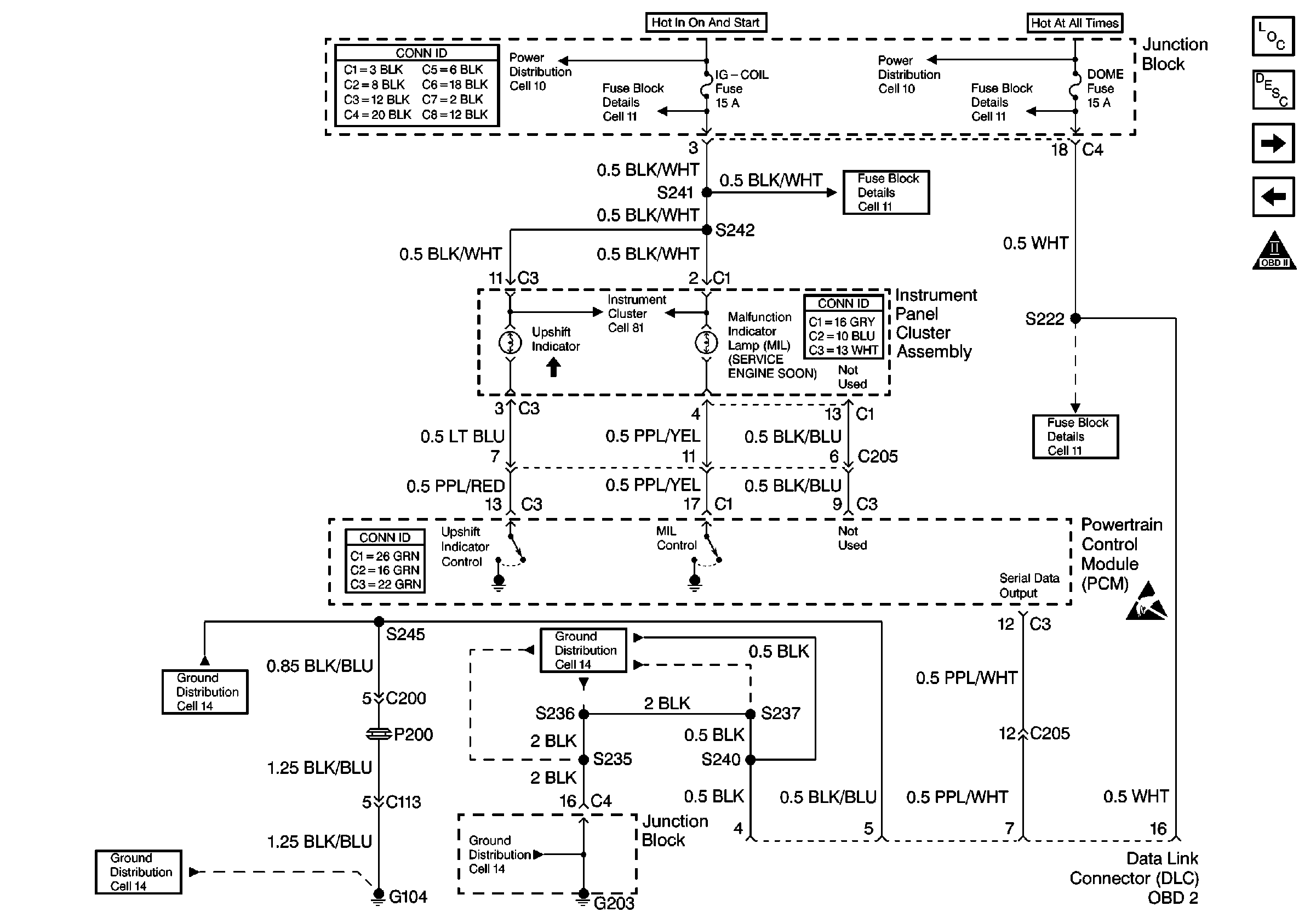
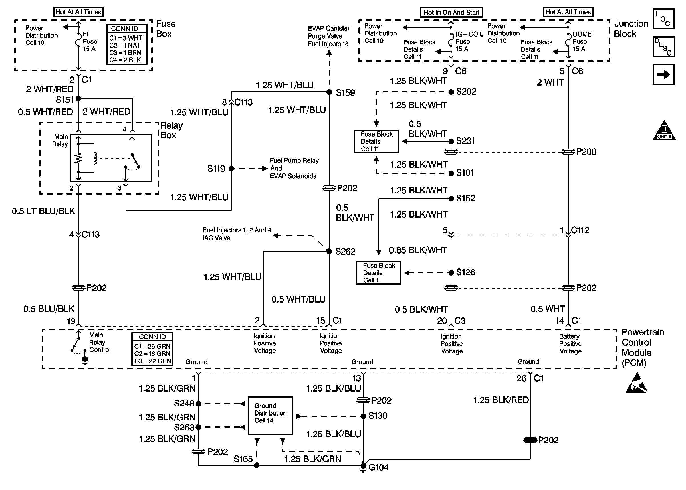
Refer to
Cell 21: MIL and DLC

and
Cell 21: Power and Ground

.
Circuit Description
The malfunction indicator lamp (MIL) is illuminated when the ignition is ON and the engine is OFF. Battery ignition voltage is supplied to the MIL. The powertrain control module will turn the MIL ON by grounding the lamp control circuit. The MIL is normally OFF when the engine is running.
Diagnostic Aids
Check for any of the following conditions:
| • | Check for a faulty indicator bulb, or an open in the instrument cluster power circuit if the engine starts and runs OK. |
| • | Check for a faulty main relay if there is no MIL and the engine cranks but will not start. |
| • | Check for a shorted to ground 5 volt reference circuit (i.e. TP Sensor, MAP Sensor, ISC Motor) if there is no scan tool data, no MIL, and the engine cranks but will not start. |
| • | A faulty electrical connection to the PCM. |
An intermittent malfunction may be caused by a fault in the MIL electrical circuit. Inspect the wiring harness and components for any of the following conditions:
| • | Backed out terminals. |
| • | Improper mating of terminals. |
| • | Broken electrical connector locks. |
| • | Improperly formed or damaged terminals. |
| • | Faulty terminal to wire connections. |
| • | Physical damage to the wiring harness. |
| • | A broken wire inside the insulation. |
| • | Corrosion of electrical connections, splices, or terminals. |
Test Description
The numbers below refer to the step numbers in the Diagnostic Table.
-
The Powertrain OBD System Check prompts the technician to complete some basic checks and store the freeze frame data on the scan tool if applicable. This creates an electronic copy of the data taken when the fault occurred. The information is then stored in the scan tool for later reference.
-
This step will verify whether the MIL circuit is at fault or if the PCM is not providing a ground path for the MIL circuit.
-
This step will verify the condition of the MIL control circuit. The PCM is providing the ground for the test light.
-
This step checks for an open in the Ignition Positive Voltage circuits from the main relay. The engine may start and run but there will be no MIL control or serial data if the circuit is open between the last two circuit splices before the PCM.
-
This step checks for a short to ground in the PCM 5 volt reference circuit. The MIL will be inoperative and the engine will not start or run if the reference voltage circuit is shorted to ground. Check the circuit wiring and the sensors and components using the 5 volt reference circuit for shorts to ground.
Step | Action | Value(s) | Yes | No | ||||||
|---|---|---|---|---|---|---|---|---|---|---|
Did you perform the Powertrain On-Board Diagnostic (OBD) System Check? | -- | |||||||||
2 | Check for an open in the following fuses:
Was an open fuse found? | -- | ||||||||
3 | Attempt to start the engine. Does the engine start? | -- | ||||||||
4 | Install a scan tool and select data display. Does the scan tool display any data? | -- | ||||||||
Does the MIL illuminate? | -- | |||||||||
6 |
Does test light illuminate? | -- | ||||||||
Does the test light illuminate when the ignition switch is turned ON, and does the test light go OFF when the ignition switch is turned OFF? | -- | |||||||||
8 | Repair the open in the BLK/WHT wire between the Junction Block and the I/P cluster assembly. Refer to Wiring Repairs in Wiring Systems. Is the action complete? | -- | -- | |||||||
9 | Locate and repair the open in the PPL/YEL wire between the I/P cluster assembly and the PCM. Refer to Wiring Repairs in Wiring Systems. Is the action complete? | -- | -- | |||||||
Does the test light illuminate at each terminal? | -- | |||||||||
11 | Backprobe the PCM electrical connector terminal C3-20 using a test light connected to ground. Does the test light illuminate? | -- | ||||||||
12 | Repair the open in the ignition positive voltage circuit between the IG-COIL fuse and the PCM. Refer to Wiring Repairs in Wiring Systems. Is the action complete? | -- | -- | |||||||
13 |
Was a repair necessary? | -- | ||||||||
14 |
Was the measured voltage at the specified value? | 5 volts | ||||||||
Was a repair necessary? | -- | |||||||||
16 |
Does the test light illuminate at each terminal? | -- | ||||||||
17 | Repair the open in the PCM ground circuits between the PCM and the G104 ground. Refer to Wiring Repairs in Wiring Systems. Is the action complete? | -- | -- | |||||||
18 | Replace the PCM. Refer to Powertrain Control Module Replacement . Is the action complete? | -- | -- | |||||||
19 |
Is the action complete? | -- | -- | |||||||
20 | Repair the short to ground in the IG-COIL fuse or the FI fuse circuits. Refer to Wiring Repairs in Wiring Systems. Is the action complete? | -- | -- | |||||||
21 |
Did the MIL illuminate when the ignition was ON and then turn OFF after the engine was started? | -- | System OK | Go to the Applicable Diagnostic Table |
