Removal Procedure
- Raise and support the vehicle. Refer to Lifting and Jacking the Vehicle in General Information.
- Remove the rear tire and wheel assembly. Refer to Wheel Removal .
- Remove the brake drum/hub assembly (6).
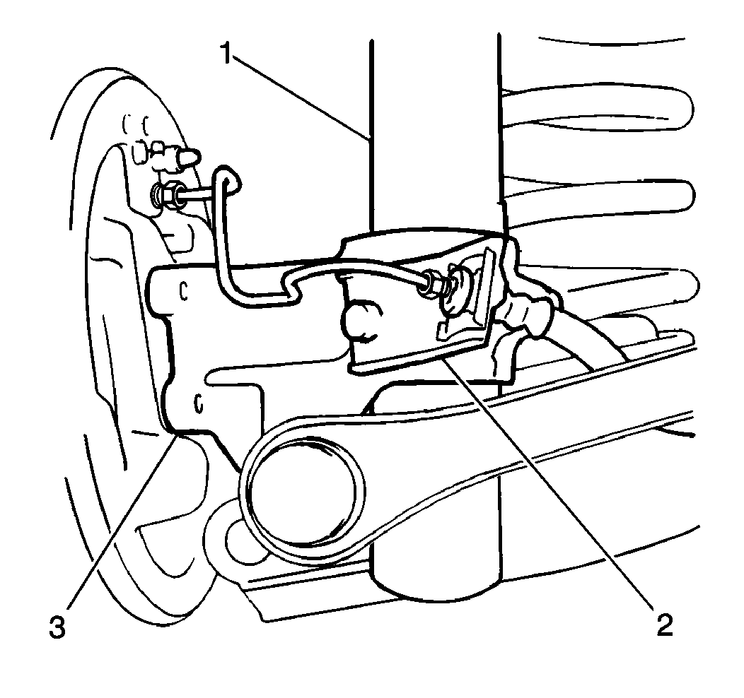
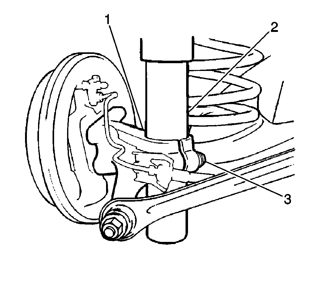
- Remove the brake hose bracket (2) from the knuckle (3).
- If the vehicle is ABS equipped, disconnect the wheel speed sensor electrical connector.
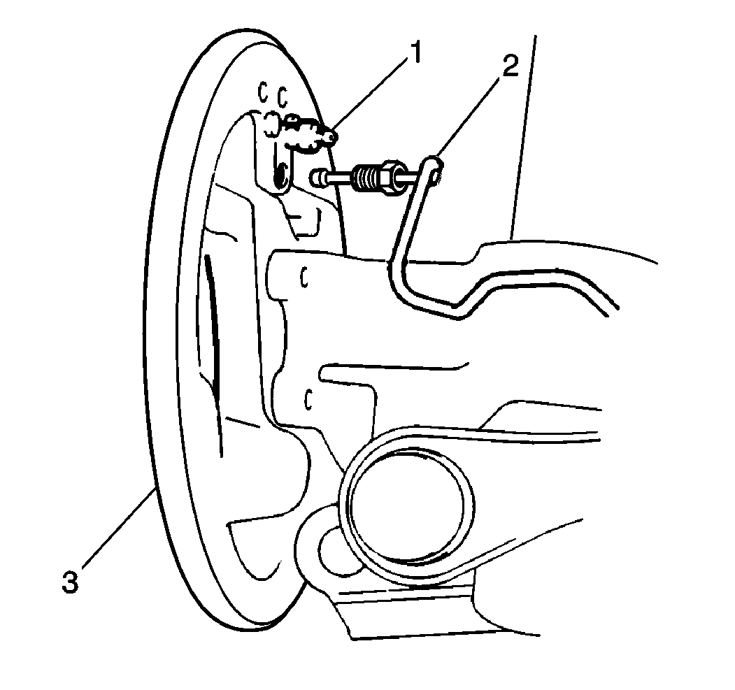
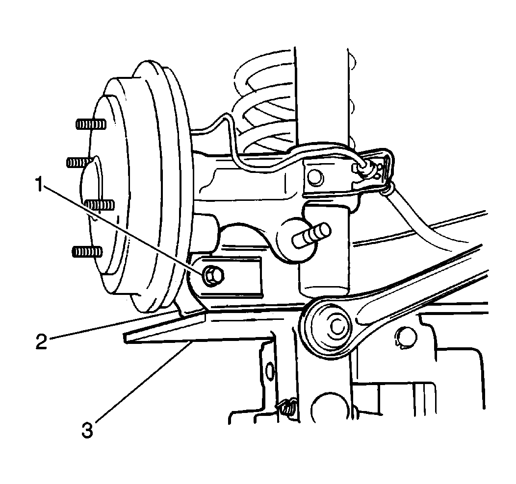
- Remove the brake pipe from the brake backing plate (3). Insert the backing plate breather plug cap (1) onto the pipe (2) in order to prevent fluid from spilling.
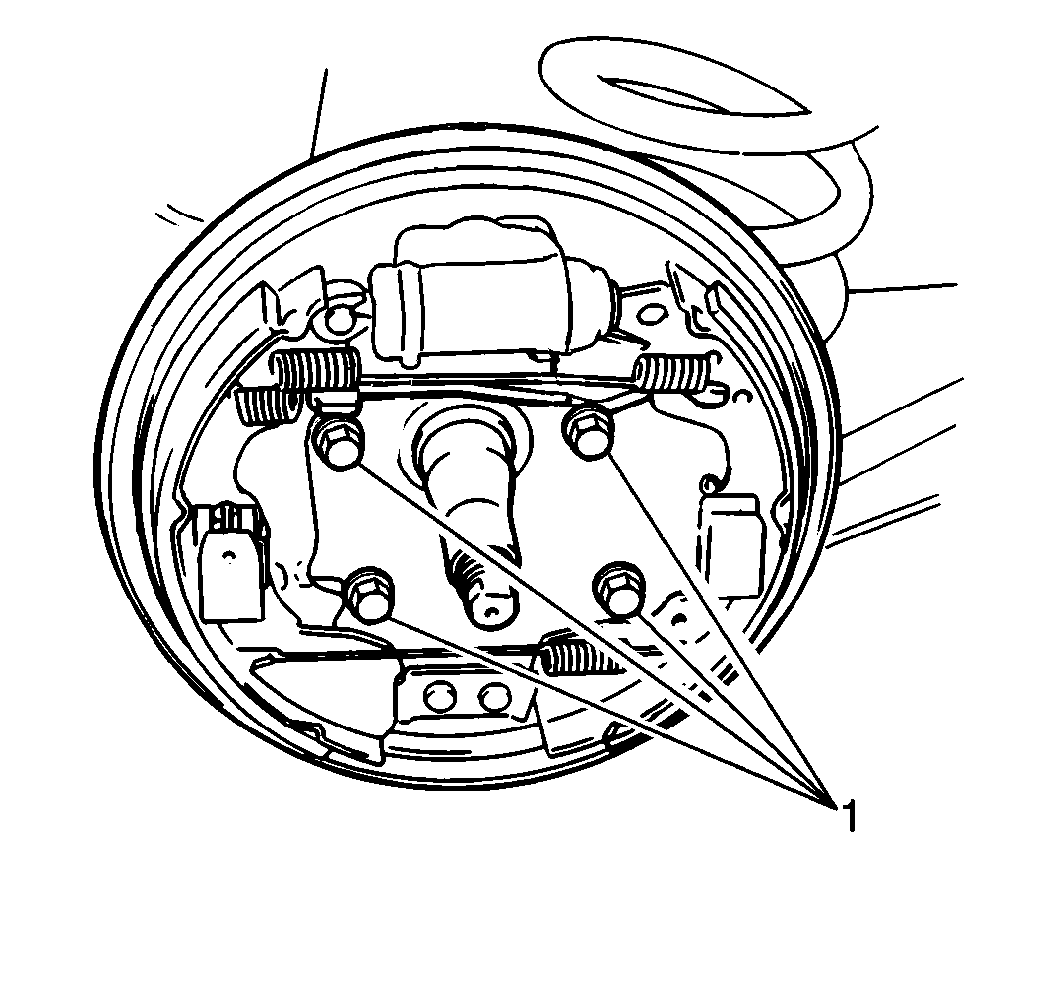
- Remove the brake backing plate from the knuckle by removing the four bolts (1).
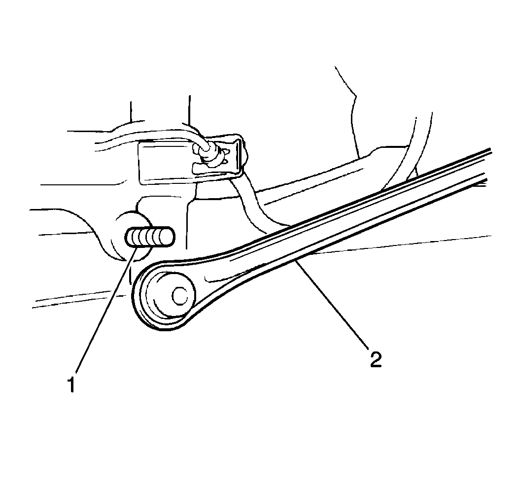
- Remove the control rod-to-knuckle nut and the washer.
- Remove the control rod (2) from the knuckle (1).
- Support the suspension arm using a floor jack.
- Remove the strut-to-knuckle bolt (3).
- Remove the suspension arm-to-knuckle bolt and the nut (1).
- Remove the knuckle from the suspension arm and the nut.
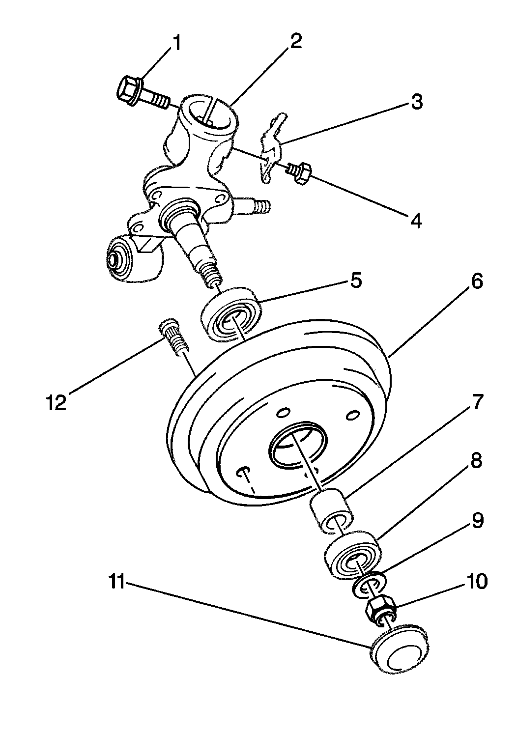
| 3.1. | Remove the spindle nut dust cap (11). Use a flat-bladed tool in order to pry off the cap. |
| 3.2. | Unstake and remove the spindle nut (10) and the washer (9). |
| 3.3. | Gently tap on the brake drum/hub assembly (6) using a hammer in order to break the assembly loose from the spindle. |
Installation Procedure
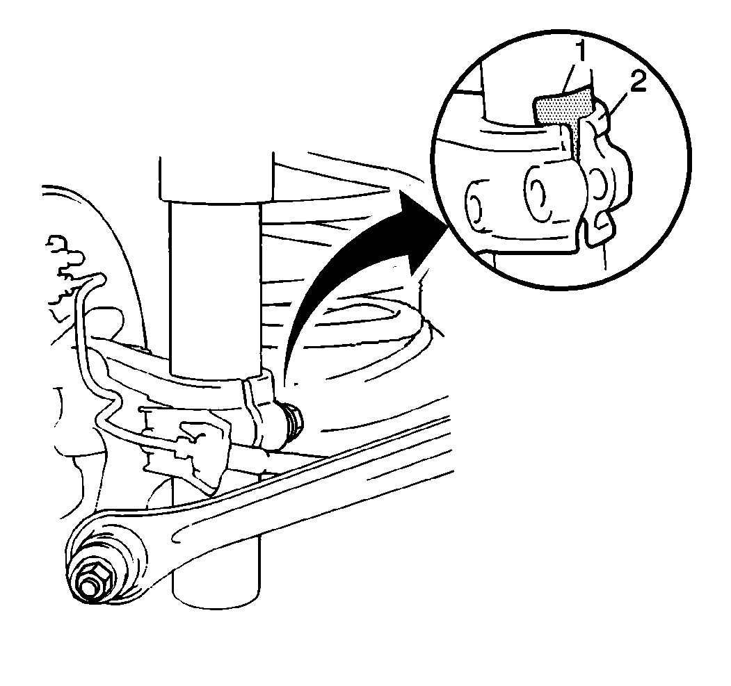
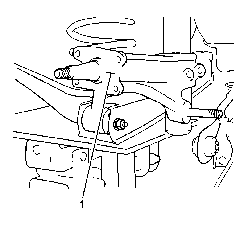
- Install the knuckle (2) to the strut. Position the bottom of the strut alignment projection (1) inside the knuckle opening.
- Install the strut-to-knuckle bolt.
- Install the suspension arm-to-knuckle bolt and the nut (1).
- Install the control rod to the knuckle stud. Secure the control rod with a washer and nut.
- Remove the floor jack.
- Apply GM P/N 12346240, or equivalent, to the mating surfaces of the brake backing plate and the suspension knuckle (1).
- Install the brake backing plate to the knuckle. Secure the plate with four bolts.
- Install the brake fluid pipe to the brake backing plate.
- If the vehicle is ABS equipped, connect the wheel speed sensor electrical connector.
- Install the bleeder valve cap onto the bleeder valve.
- Install the brake hose bracket to the knuckle.
- Install the brake drum/hub assembly to the knuckle spindle.
- Install the washer and the spindle nut to the knuckle spindle.
- Stake the spindle nut.
- Install the spindle nut dust cap.
- Install the rear tire and wheel assembly. Refer to Wheel Installation .
- Lower the vehicle.
- Bleed the brake system. Refer to Vehicle Certification Label .
- Inspect the brake drum for free rotation. Refer to Brake Drum Inspection .
- Inspect the brake system performance.
- Inspect for brake fluid leaks. Refer to Brake Fluid Leak .

Notice: Use the correct fastener in the correct location. Replacement fasteners must be the correct part number for that application. Fasteners requiring replacement or fasteners requiring the use of thread locking compound or sealant are identified in the service procedure. Do not use paints, lubricants, or corrosion inhibitors on fasteners or fastener joint surfaces unless specified. These coatings affect fastener torque and joint clamping force and may damage the fastener. Use the correct tightening sequence and specifications when installing fasteners in order to avoid damage to parts and systems.
Tighten
Tighten the strut-to-knuckle bolt to 60 N·m (44 lb ft).
Tighten
Tighten the suspension arm-to-knuckle nut and the bolt to 40 N·m
(29 lb ft).
Tighten
Tighten the control rod-to-suspension knuckle nut to 80 N·m
(59 lb ft).
Tighten
Tighten the brake backing plate bolts to 23 N·m (17 lb ft).
Tighten
Tighten the brake fluid pipe flare nut to 16 N·m (12 lb ft).
Tighten
Tighten the brake hose bracket bolt to 23 N·m (17 lb ft).
Tighten
| • | If the vehicle is wheel hub equipped, tighten the spindle nut to 170 N·m (120 lb ft). |
| • | If the vehicle is non-wheel hub equipped, tighten the spindle nut to 100 N·m (74 lb ft). |
