Front Floor Panel Carpet Replacement 2 Door
Removal Procedure
- Disconnect the negative battery cable.
- Disable the SIR system. Refer to Disabling the SIR System in SIR.
- Remove the front seats from the vehicle. Refer to Front Seat Replacement - Bucket in Seats.
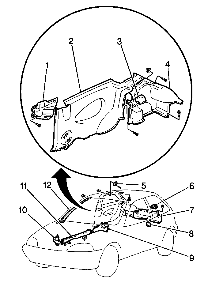
- Remove the right-side hinge pillar trim panel (10) by removing the plastic retaining clips.
- Remove the left-side hinge pillar trim panel by removing the plastic retaining clips.
- Remove the front right sill plate (11) by removing the plastic retaining clips.
- Remove the front left sill plate by removing the plastic retaining clips.
- Remove the lower rear quarter trim panels. Refer to Rear Quarter Trim Panel Replacement .
- Remove the shifter boot from the console, if equipped.
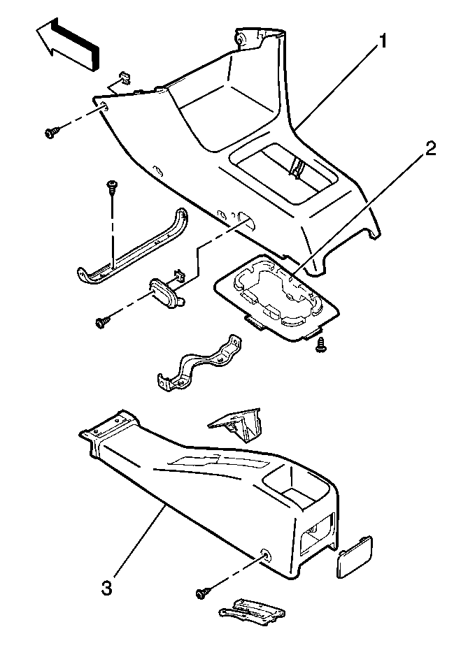
- Remove the shift control lever console (1) by removing the 4 screws.
- Remove the parking brake lever bezel (3) by removing 2 screws.
- Remove the lower anchor bolts of the front seat belt from the floorpan.
- Remove the 4 plastic retainers attaching the carpet under the instrument panel near the bulkhead.
- Remove the console instrument panel mounting bracket by removing the retainer.
- Disconnect the sensing diagnostic module (SDM) electrical connector.
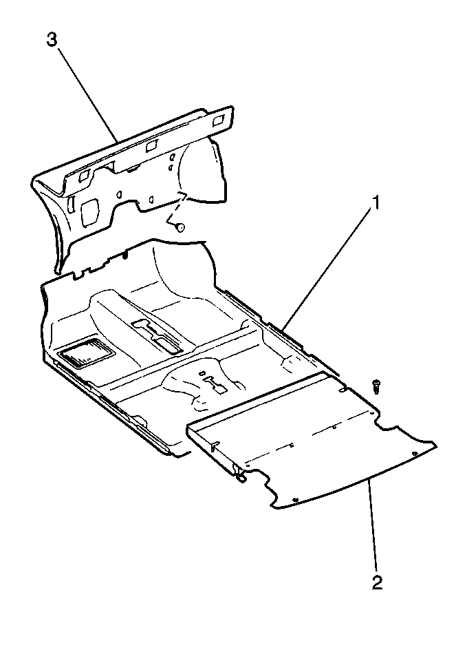
- Remove the passenger compartment floor carpet (1) from the vehicle.
Caution: Unless directed otherwise, the ignition and start switch must be in the OFF or LOCK position, and all electrical loads must be OFF before servicing any electrical component. Disconnect the negative battery cable to prevent an electrical spark should a tool or equipment come in contact with an exposed electrical terminal. Failure to follow these precautions may result in personal injury and/or damage to the vehicle or its components.
Caution: This vehicle is equipped with a Supplemental Inflatable Restraint (SIR) System. Failure to follow the correct procedure could cause the following conditions:
• Air bag deployment • Personal injury • Unnecessary SIR system repairs • Refer to SIR Component Views in order to determine if you are performing service on or near the SIR components or the SIR wiring. • If you are performing service on or near the SIR components or the SIR wiring, disable the SIR system. Refer to Disabling the SIR System.
Installation Procedure
- Install the front floor carpet (1) into the vehicle.
- Connect the sensing diagnostic module (SDM) electrical connector.
- Install the console-to-instrument panel mounting bracket. Secure the bracket with the retainer.
- Secure the carpet under the instrument panel with 4 plastic retainers.
- Install the lower anchor bolts of the front seat belt to the floorpan.
- Install the parking brake lever bezel (3) to the vehicle. Secure the bezel with the 2 screws.
- Install the shift control lever console (1) to the vehicle. Secure the console with the 4 screws.
- Install the shifter boot, if equipped.
- Install the lower rear quarter trim panels. Refer to Rear Quarter Trim Panel Replacement .
- Install the left-side hinge pillar trim panel. Secure the panel with plastic retaining clips.
- Install the right-side hinge pillar trim panel (10). Secure the panel with plastic retaining clips.
- Install the left front sill plate. Secure the plate with plastic retaining clips.
- Install the right front sill plate (11). Secure the plate with plastic retaining clips.
- Install the front seat to the vehicle. Refer to Front Seat Replacement - Bucket in Seats.
- Enable the SIR system. Refer to Enabling the SIR System in SIR.
- Connect the negative battery cable.


Notice: Use the correct fastener in the correct location. Replacement fasteners must be the correct part number for that application. Fasteners requiring replacement or fasteners requiring the use of thread locking compound or sealant are identified in the service procedure. Do not use paints, lubricants, or corrosion inhibitors on fasteners or fastener joint surfaces unless specified. These coatings affect fastener torque and joint clamping force and may damage the fastener. Use the correct tightening sequence and specifications when installing fasteners in order to avoid damage to parts and systems.
Tighten
Tighten the anchor bolts to 45 N·m (33 lb ft).

Front Floor Panel Carpet Replacement 4 Door
Removal Procedure
- Disconnect the negative battery cable.
- Disable the SIR system. Refer to Disabling the SIR System in SIR.
- Remove the front seat from the vehicle. Refer to Front Seat Replacement - Bucket .
- Remove the right-side hinge pillar trim panel (8) by removing the plastic retaining clips.
- Remove the left-side hinge pillar trim panel by removing the plastic retaining clips.
- Remove the front right sill plate (9) by removing the plastic retaining clips.
- Remove the front left sill plate by removing the plastic retaining clips.
- Remove the right rear sill plate (7) by removing the plastic retaining clips.
- Remove the left rear sill plate by removing the plastic retaining clips.
- Gently pry the following components from the vehicle:
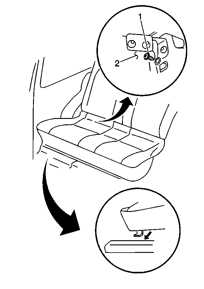
- Raise the rear seat cushion at the front edge, disengaging the retaining clips.
- Remove the shifter boot from the console, if equipped.
- Remove the shift control lever console (1) by removing the 4 screws.
- Remove the parking brake lever bezel (3) by removing the 2 screws.
- Remove the lower anchor bolts of the front seat from the floorpan.
- Remove 4 plastic retainers attaching the carpet under the instrument panel.
- Disconnect the sensing diagnostic module (SDM) electrical connector.
- Remove the console-to-instrument panel routing bracket by removing the retainer.
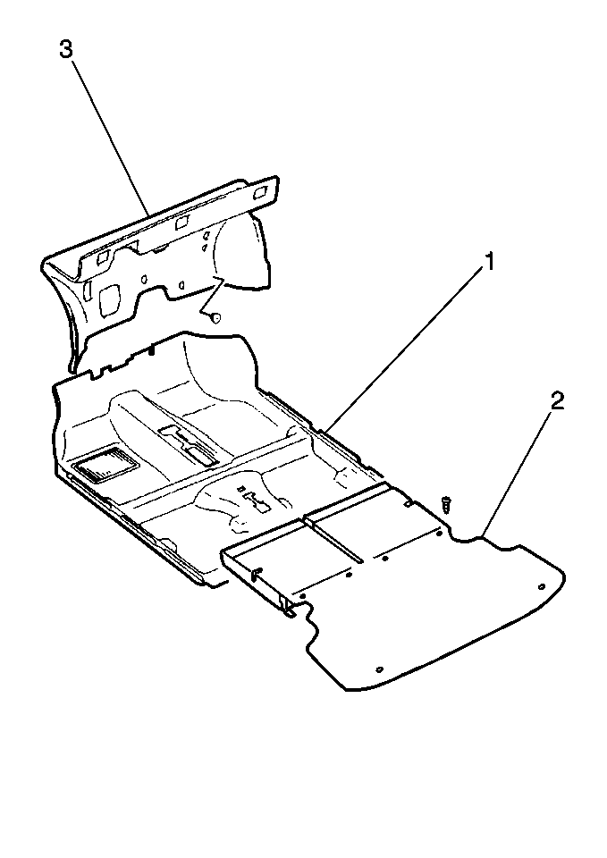
- Remove the passenger compartment floor carpet (1) from the vehicle.
Caution: Unless directed otherwise, the ignition and start switch must be in the OFF or LOCK position, and all electrical loads must be OFF before servicing any electrical component. Disconnect the negative battery cable to prevent an electrical spark should a tool or equipment come in contact with an exposed electrical terminal. Failure to follow these precautions may result in personal injury and/or damage to the vehicle or its components.
Caution: This vehicle is equipped with a Supplemental Inflatable Restraint (SIR) System. Failure to follow the correct procedure could cause the following conditions:
• Air bag deployment • Personal injury • Unnecessary SIR system repairs • Refer to SIR Component Views in order to determine if you are performing service on or near the SIR components or the SIR wiring. • If you are performing service on or near the SIR components or the SIR wiring, disable the SIR system. Refer to Disabling the SIR System.
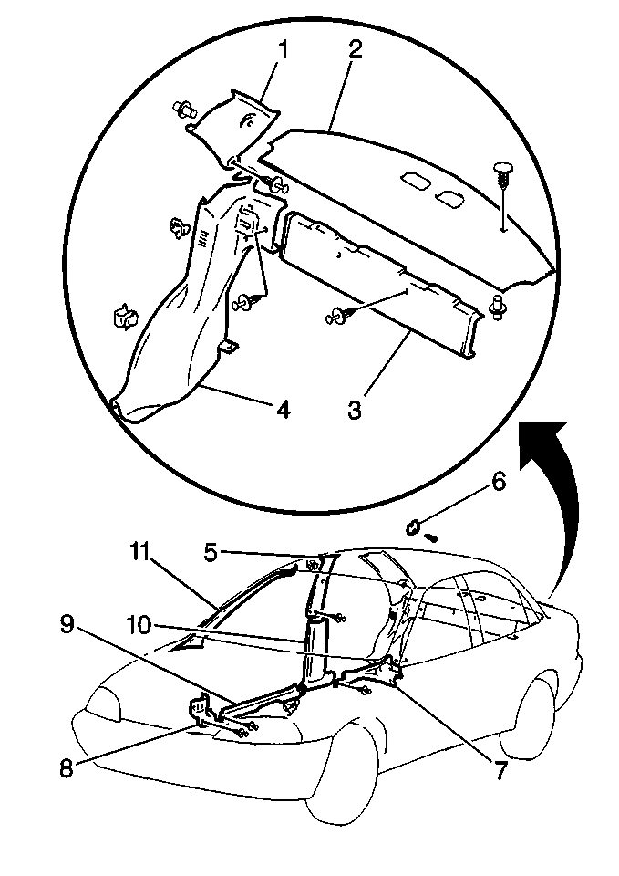
| • | The right center pillar lower trim panel (10) |
| • | The left center pillar lower trim panel |

Installation Procedure
- Install the front floor carpet (1) into the vehicle.
- Connect the sensing diagnostic module (SDM) electrical connector.
- Install the console-to-instrument panel routing bracket. Secure the bracket with the retainer.
- Secure the carpet under the instrument panel with 4 plastic retainers.
- Install the lower anchor bolts of the front seat belt to the floorpan.
- Install the parking brake lever bezel (3). Secure the bezel to the vehicle with the 2 screws.
- Install the shift control lever console (1). Secure the console to the vehicle with the 4 screws.
- Install the shifter boot, if equipped.
- Secure the front edge of the rear seat cushion by pressing the plastic retaining clips into place.
- Install the following components to the vehicle:
- Install the left-side hinge pillar trim panel. Secure the panel with plastic retaining clips.
- Install the right-side hinge pillar trim panel (8). Secure the panel with plastic retaining clips.
- Install the left rear sill plate. Secure the sill plate with plastic retaining clips.
- Install the right rear sill plate (7). Secure the sill plate with plastic retaining clips.
- Install the left front sill plate. Secure the sill plate with plastic retaining clips.
- Install the right front sill plate (9). Secure the sill plate with plastic retaining clips.
- Install the front seats to the vehicle. Refer to Front Seat Replacement - Bucket in Seats.
- Enable the SIR system. Refer to Enabling the SIR System in SIR.
- Connect the negative battery cable.


Notice: Use the correct fastener in the correct location. Replacement fasteners must be the correct part number for that application. Fasteners requiring replacement or fasteners requiring the use of thread locking compound or sealant are identified in the service procedure. Do not use paints, lubricants, or corrosion inhibitors on fasteners or fastener joint surfaces unless specified. These coatings affect fastener torque and joint clamping force and may damage the fastener. Use the correct tightening sequence and specifications when installing fasteners in order to avoid damage to parts and systems.
Tighten
Tighten the anchor bolts to 45 N·m (33 lb ft).

| • | The right center pillar lower trim panel (10) |
| • | The left center pillar lower trim panel |
