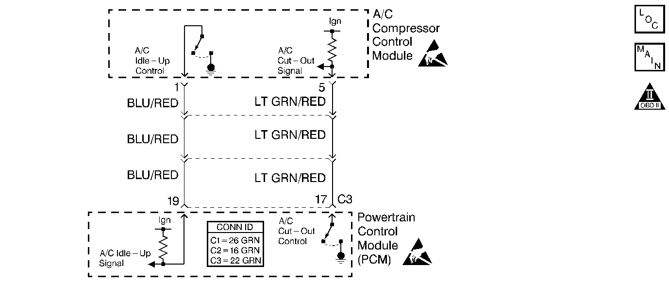
Circuit Description
When the A/C compressor clutch is ON, the A/C compressor control module sends an A/C idle-up signal to the powertrain control module (PCM). The PCM sends a signal to the idle air control (IAC) valve in order to increase the flow through the idle air passage. The engine idle speed increases as more airflow travels through the idle air passage. The increase in the idle speed prevents a rough idle or a stalling condition.
Diagnostic Aids
Check for a faulty electrical connection to the PCM.
An intermittent malfunction may be caused by a fault in the A/C idle-up electrical circuit. Inspect the wiring harness and the components for any of the following conditions:
| • | Backed out terminals |
| • | Incorrect mating of terminals |
| • | Broken electrical connector locks |
| • | Incorrectly formed terminals or damaged terminals |
| • | Faulty terminal-to-wire connections |
| • | Physical damage to the wiring harness |
| • | A broken wire inside the insulation |
| • | Corrosion of electrical connections, of splices, or of terminals |
If a condition was not found in the A/C idle-up circuit check, refer Symptoms to .
Test Description
The numbers below refer to the step numbers in the diagnostic table.
-
The Powertrain OBD System Check prompts the technician to complete some basic checks, and to store the applicable freeze frame data on the scan tool. This creates an electronic copy of the data that was taken when the fault occurred. The scan tool stores the information for later reference.
-
This step checks for an increase in the idle speed when you turn ON the A/C.
-
The A/C idle-up signal circuit at the PCM should indicate 0.0 volts when you turn ON the A/C.
-
The A/C idle-up signal circuit at the PCM should indicate B+ when you turn OFF the A/C.
-
The A/C cut-out signal circuit at the PCM should indicate 0.0 volts when you turn OFF the A/C .
-
The A/C cut-out signal circuit at the PCM should indicate B+ when you turn ON the A/C.
Step | Action | Value(s) | Yes | No |
|---|---|---|---|---|
Did you perform the Powertrain On-Board Diagnostic (OBD) System Check? | -- | |||
Does the scan tool indicate ON when you are operating the A/C? | -- | Go to Diagnostic Aids | ||
Is the voltage at the specified value? | 0 V | |||
Is the voltage at the specified value? | B+ | |||
5 |
Is the voltage at the specified value? | B+ | ||
6 |
Was a repair necessary? | -- | ||
Is the voltage at the specified value? | 0 V | |||
Is the voltage at the specified value? | B+ | Go to Diagnostic Aids | ||
9 |
Was a repair necessary? | -- | ||
10 |
Is the voltage at the specified value? | B+ | ||
11 |
Is the action complete? | -- | -- | |
12 |
Important: The replacement PCM must be programmed. Replace the PCM. Refer to Powertrain Control Module Replacement . Is the action complete? | -- | -- | |
13 | Operate the vehicle within the conditions under which the original symptom was specified. Does the system operate correctly? | -- | System OK | Go to Diagnostic Aids |
