For 1990-2009 cars only
Catalytic Converter Replacement RPO LSJ
Removal Procedure
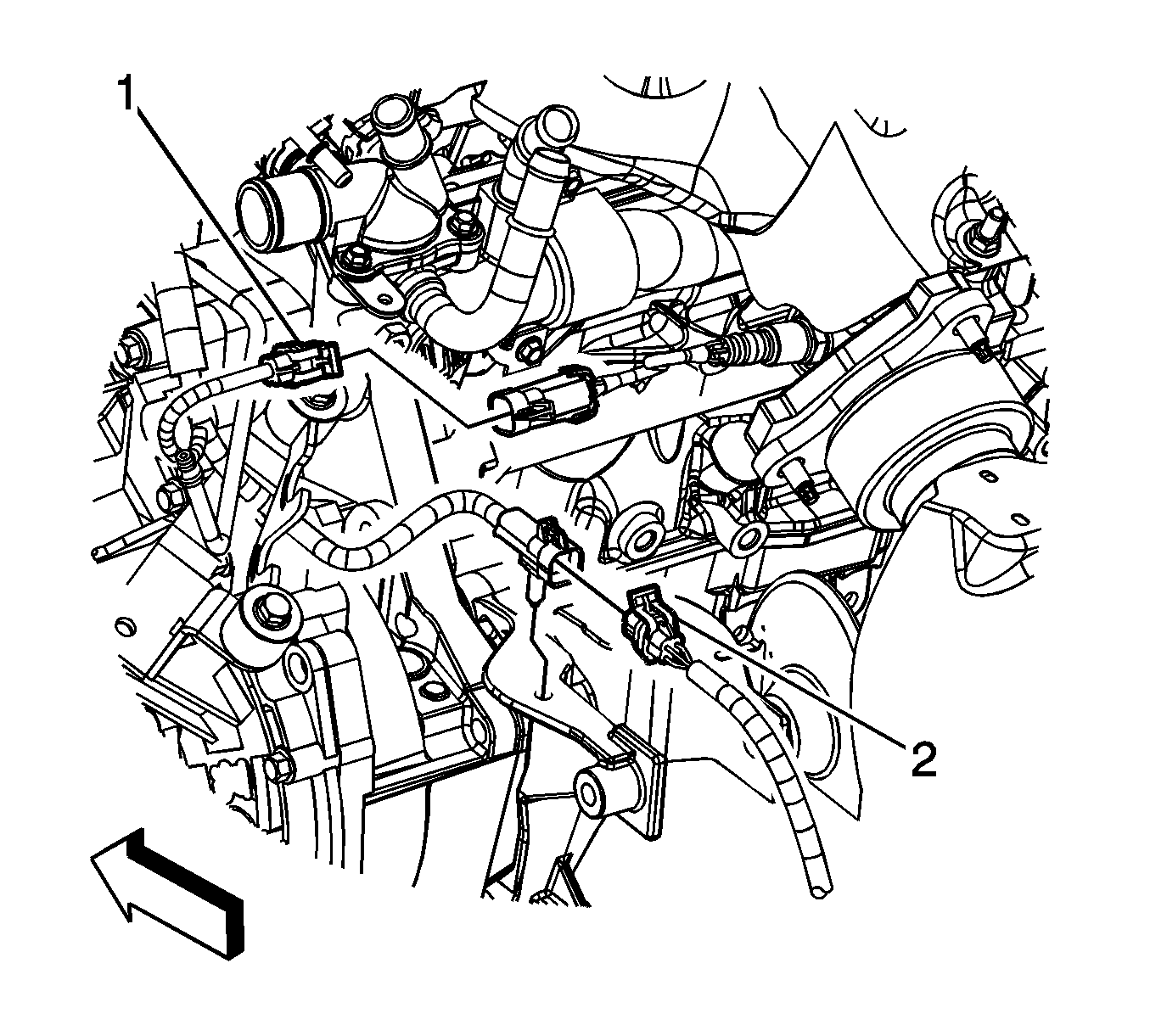
- Remove the heated oxygen sensor (HO2S) connector position assurance (CPA) retainer.
- Disconnect the HO2S lead (2) from the engine harness electrical connector.
- Raise and support the vehicle. Refer to Lifting and Jacking the Vehicle .
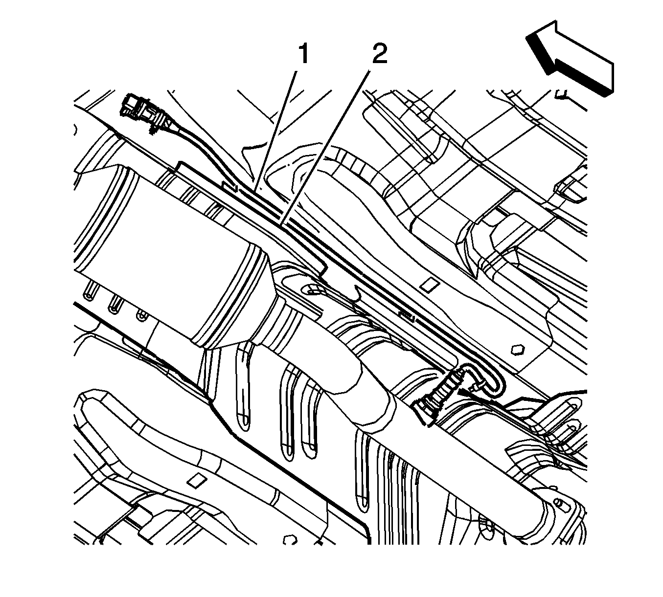
- Bend the heat shield trough (2) down slightly until the HO2S lead (1) can be removed.
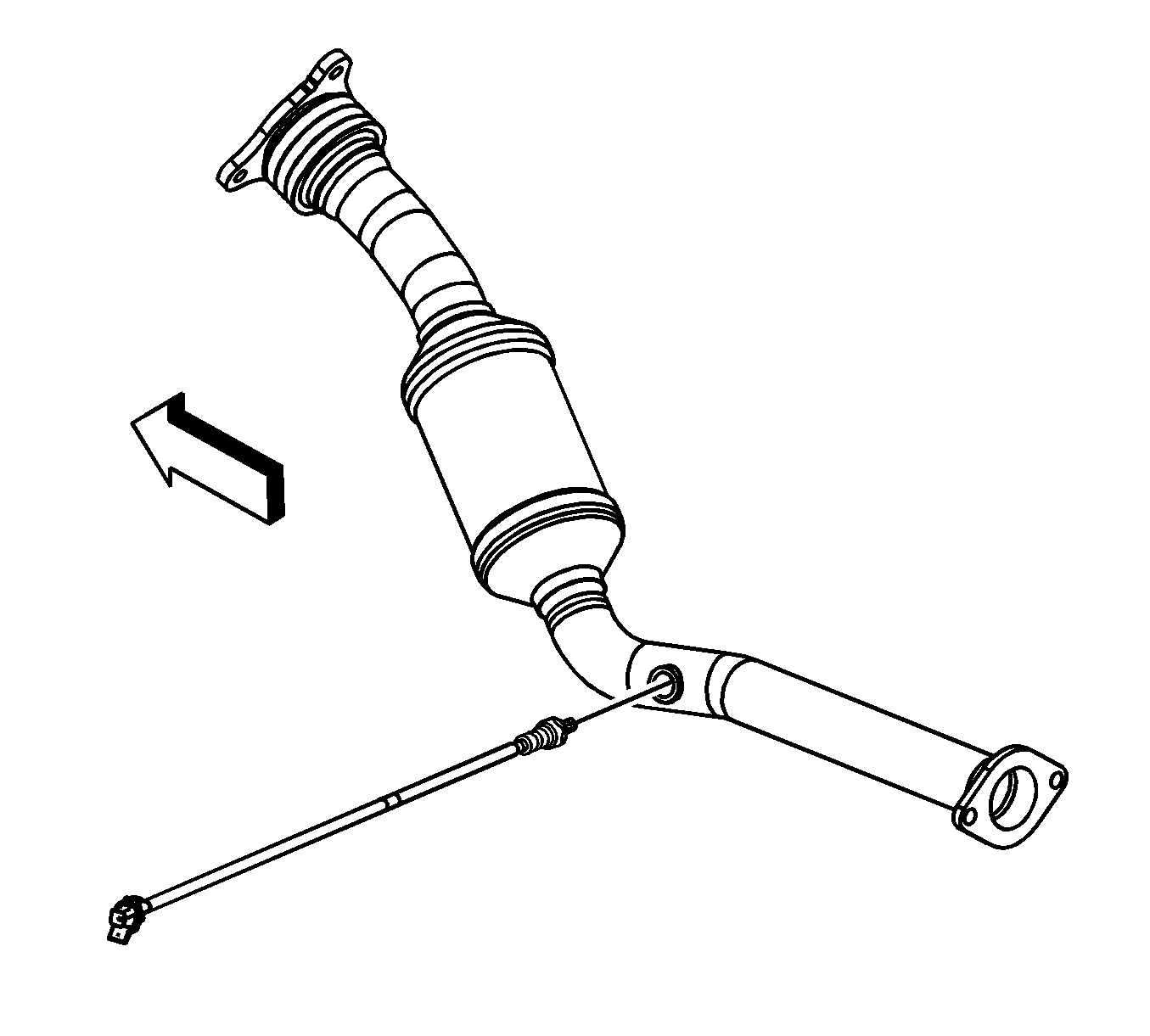
- Remove the HO2S.
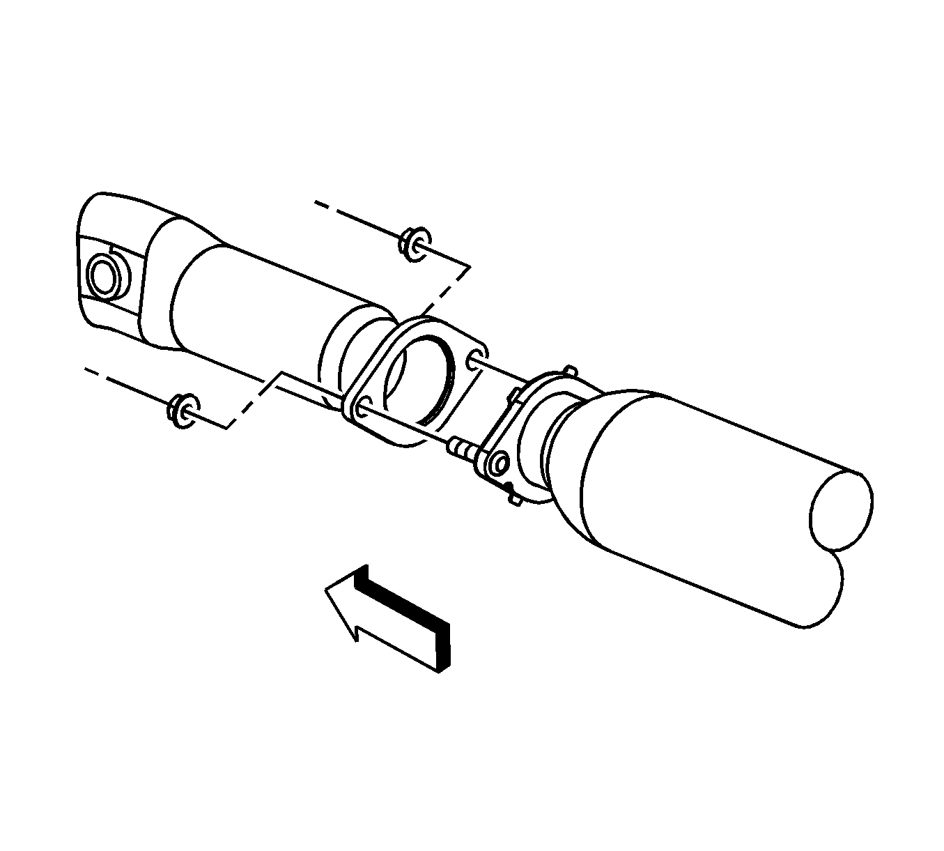
- Remove the catalytic converter to muffler pipe nuts.
- Pull the muffler pipe rearward and down until the studs are removed from the catalytic converter.
- Remove the catalytic converter pipe to exhaust manifold nuts.
- Remove the catalytic converter.
- Remove and discard the exhaust gaskets.
- Clean the flange mating surfaces of any remaining gasket material.
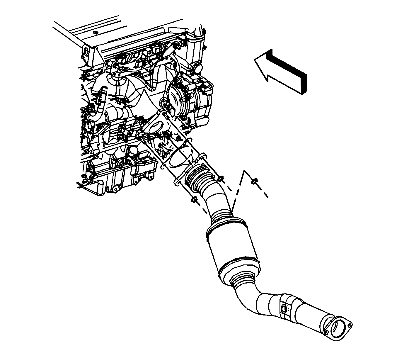
Installation Procedure
- Install a NEW gasket onto the exhaust manifold studs.
- Install the catalytic converter.
- Install the catalytic converter pipe to exhaust manifold nuts.
- Install a NEW gasket onto the muffler pipe studs.
- Pull the muffler pipe rearward and up until the studs are installed to the catalytic converter.
- Remove the catalytic converter to muffler pipe nuts.
- If reinstalling the old HO2S, coat the threads with anti-seize compound G/M P/N 12377953, or equivalent.
- Install the HO2S.
- Route the HO2S lead (1) through the heat shield trough (2), once done bend the trough until the HO2S lead is secured.
- Lower the vehicle.
- Connect the HO2S lead (2) to the engine harness electrical connector.
- Install the HO2S CPA retainer.

Notice: Refer to Fastener Notice in the Preface section.
Tighten
Tighten the nuts to 50 N·m (37 lb ft).

Tighten
Tighten the nuts to 30 N·m (22 lb ft).

Tighten
Tighten the sensor to 42 N·m (31 lb ft).


Catalytic Converter Replacement RPO L61
Removal Procedure
- If equipped with regular production option (RPO) MN5, remove the heated oxygen sensor (HO2S) connector position assurance (CPA) retainer.
- Disconnect the HO2S lead from the engine harness electrical connector (4).
- If equipped with RPO M86, remove the HO2S CPA retainer (4).
- Disconnect the HO2S lead from the engine harness electrical connector (5).
- Remove the wheel drive shaft heat shield. Refer to Wheel Drive Shaft Heat Shield Replacement .
- Bend the heat shield trough (2) down slightly until the HO2S lead (1) can be removed.
- Remove the HO2S.
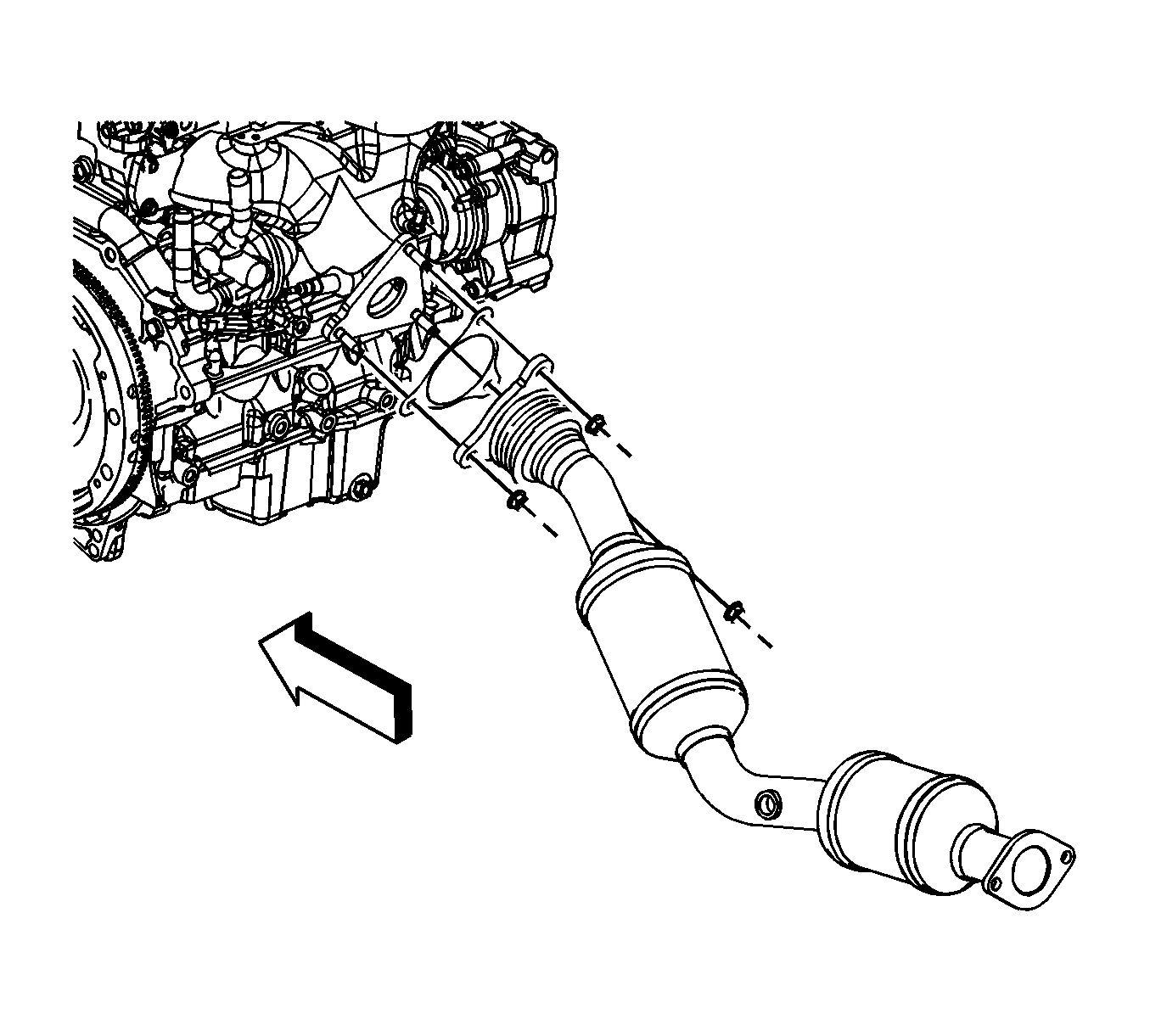
- Remove the catalytic converter to muffler pipe nuts.
- Pull the muffler pipe rearward and down until the studs are removed from the catalytic converter.
- Remove the catalytic converter pipe to exhaust manifold nuts.
- Remove the catalytic converter.
- Remove and discard the exhaust gaskets.
- Clean the flange mating surfaces of any remaining gasket material.
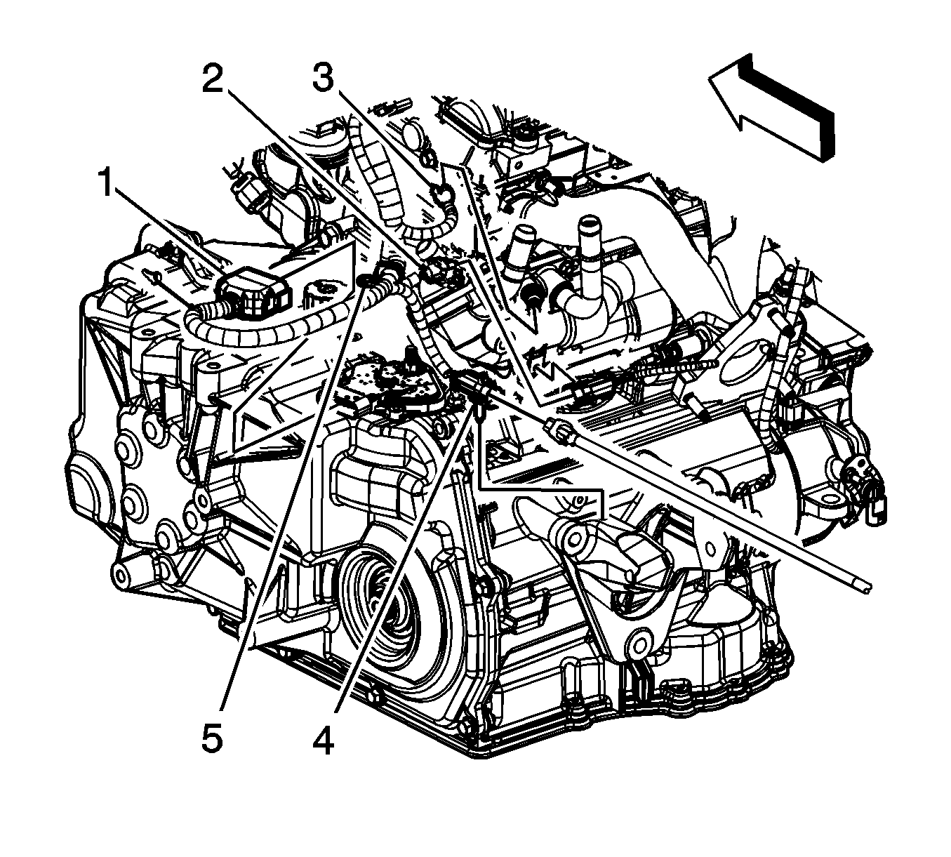
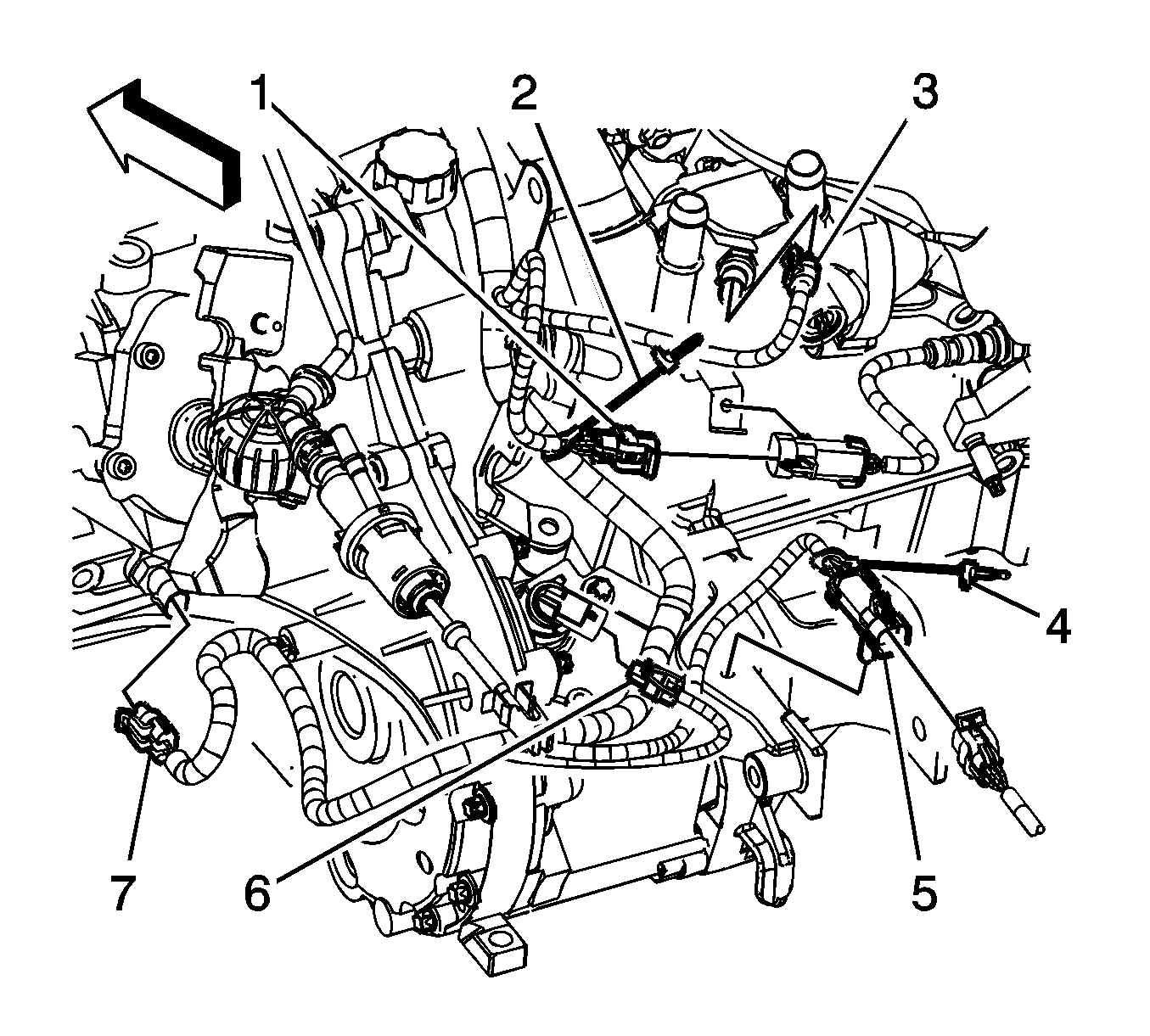


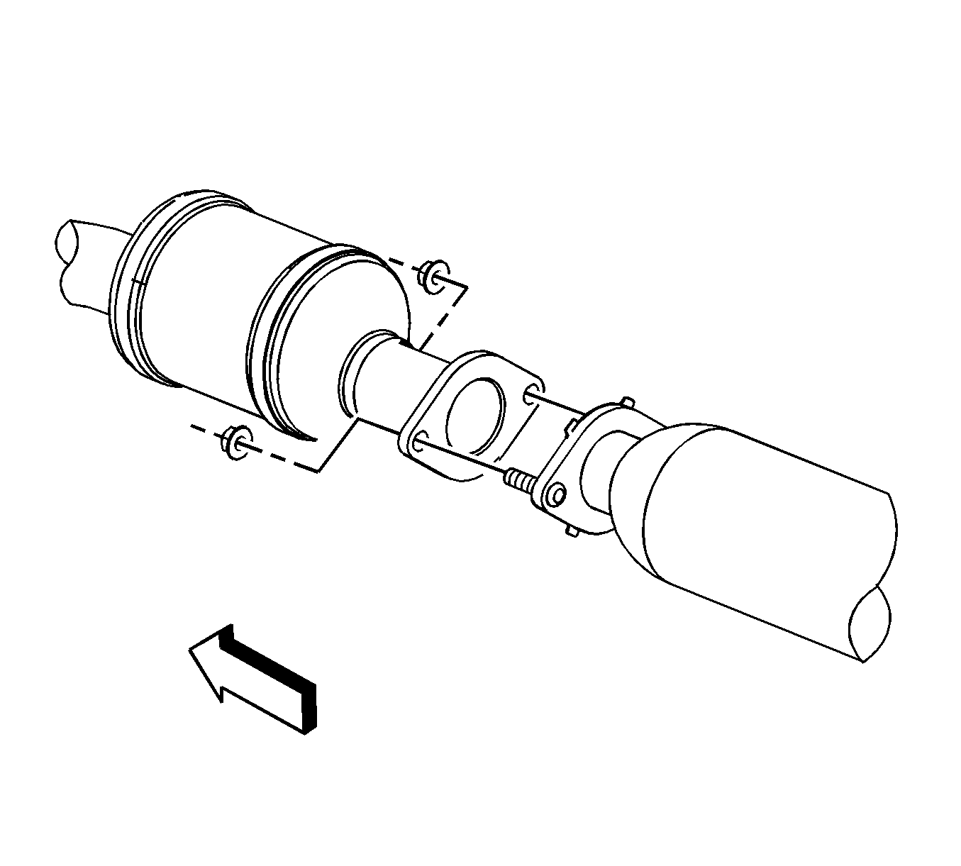
Installation Procedure
- Install a NEW gasket onto the exhaust manifold studs.
- Install the catalytic converter.
- Install the catalytic converter pipe to exhaust manifold nuts.
- Install a NEW gasket onto the muffler pipe studs.
- Pull the muffler pipe rearward and up until the studs are installed to the catalytic converter.
- Install the catalytic converter to muffler pipe nuts.
- If reinstalling the old HO2S, coat the threads with anti-seize compound, or equivalent.
- Install the HO2S.
- Route the HO2S lead (1) through the heat shield trough, once done bend the trough (2) until the HO2S lead is secured.
- Install the wheel drive shaft heat shield. Refer to Wheel Drive Shaft Heat Shield Replacement .
- If equipped with RPO M86, connect the HO2S lead to the engine harness electrical connector (5).
- Install the HO2S CPA retainer (4).
- If equipped with RPO MN5, connect the HO2S lead to the engine harness electrical connector (4).
- Install the HO2S CPA retainer.

Notice: Refer to Fastener Notice in the Preface section.
Tighten
Tighten the nuts to 50 N·m (37 lb ft).

Tighten
Tighten the nuts to 30 N·m (22 lb ft).

Tighten
Tighten the sensor to 42 N·m (31 lb ft).


Catalytic Converter Replacement RPO LE5
Removal Procedure
- If equipped with regular production option (RPO) MN5, remove the heated oxygen sensor (HO2S) connector position assurance (CPA) retainer.
- Disconnect the HO2S lead from the engine harness electrical connector (4).
- If equipped with RPO M86, remove the HO2S CPA retainer (4).
- Disconnect the HO2S lead from the engine harness electrical connector (5).
- Bend the heat shield trough (2) down slightly until the HO2S lead (1) can be removed.
- Remove the HO2S.
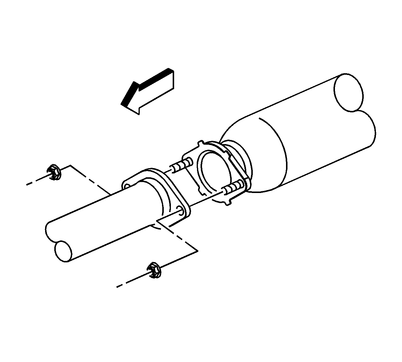
- Remove the catalytic converter to muffler pipe nuts.
- Pull the muffler pipe rearward and down until the studs are removed from the catalytic converter.
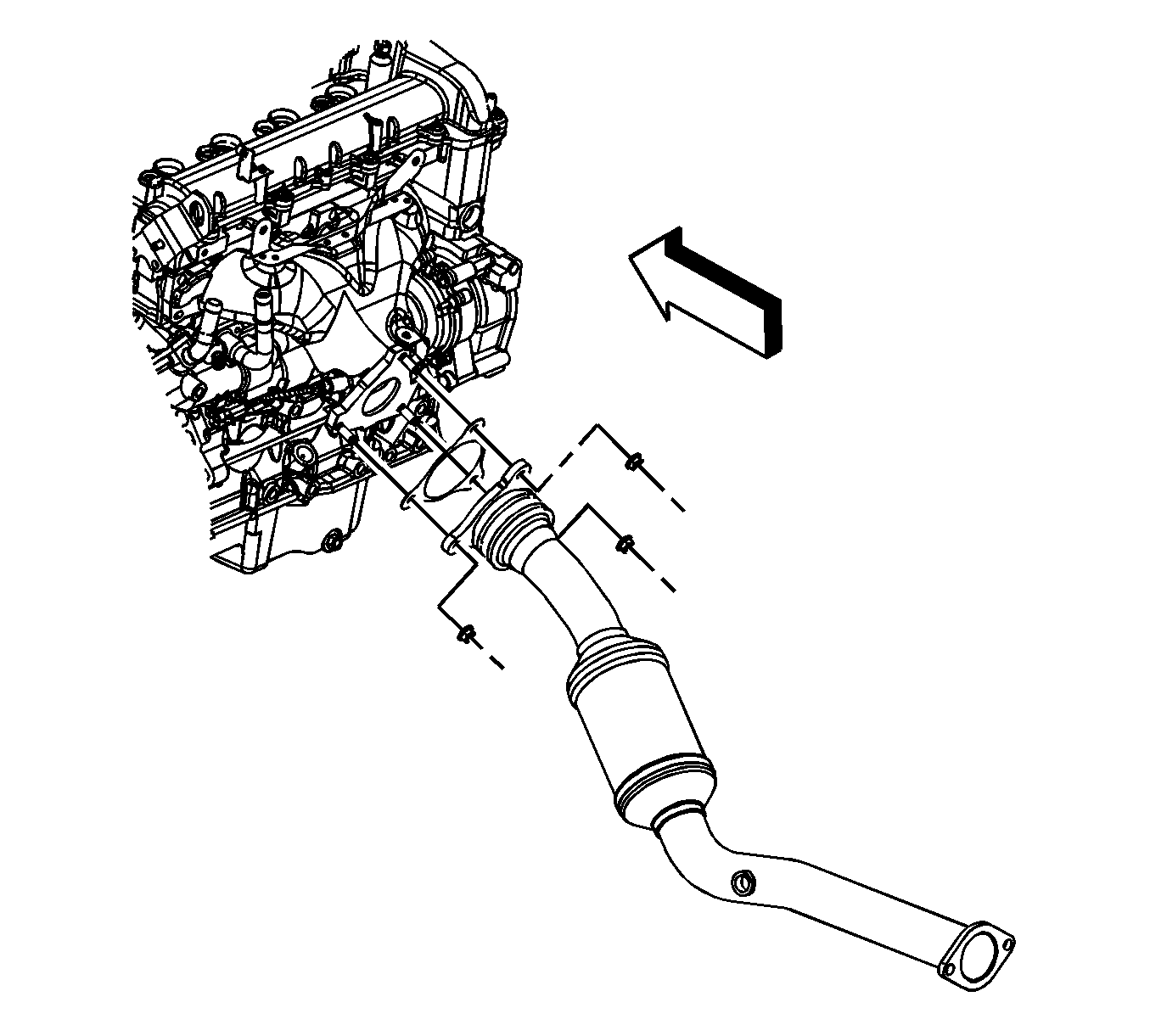
- Remove the catalytic converter pipe to exhaust manifold nuts.
- Remove the catalytic converter.
- Remove and discard the exhaust gaskets.
- Clean the flange mating surfaces of any remaining gasket material.


Installation Procedure
- Install a NEW gasket onto the exhaust manifold studs.
- Install the catalytic converter.
- Install the catalytic converter pipe to exhaust manifold nuts.
- Install a NEW gasket onto the muffler pipe studs.
- Pull the muffler pipe rearward and up until the studs are installed to the catalytic converter.
- Install the catalytic converter to muffler pipe nuts.
- If reinstalling the old HO2S, coat the threads with anti-seize compound, or equivalent.
- Install the HO2S.
- Route the HO2S lead (1) through the heat shield trough (2), once done, bend the trough until the HO2S lead is secured.
- If equipped with RPO M86, connect the HO2S lead to the engine harness electrical connector (5).
- Install the HO2S CPA retainer (4).
- If equipped with RPO MN5, connect the HO2S lead to the engine harness electrical connector (4).
- Install the HO2S CPA retainer.

Notice: Refer to Fastener Notice in the Preface section.
Tighten
Tighten the nuts to 50 N·m (37 lb ft).

Tighten
Tighten the nuts to 30 N·m (22 lb ft).

Tighten
Tighten the sensor to 42 N·m (31 lb ft).


