For 1990-2009 cars only
Tools Required
J 38400 Brake Shoe Spanner and Spring Remover
Caution: Refer to Brake Dust Caution in the Preface section.
Removal Procedure
- Raise and support the vehicle. Refer to Lifting and Jacking the Vehicle .
- Remove the tire and wheel assembly. Refer to Tire and Wheel Removal and Installation .
- Remove the brake drum. Refer to Brake Drum Replacement .
- Remove the adjuster spring (1). Disengage the adjuster spring hook end from the tab on the adjuster actuator lever, then release the spring from the brake shoe web hole.
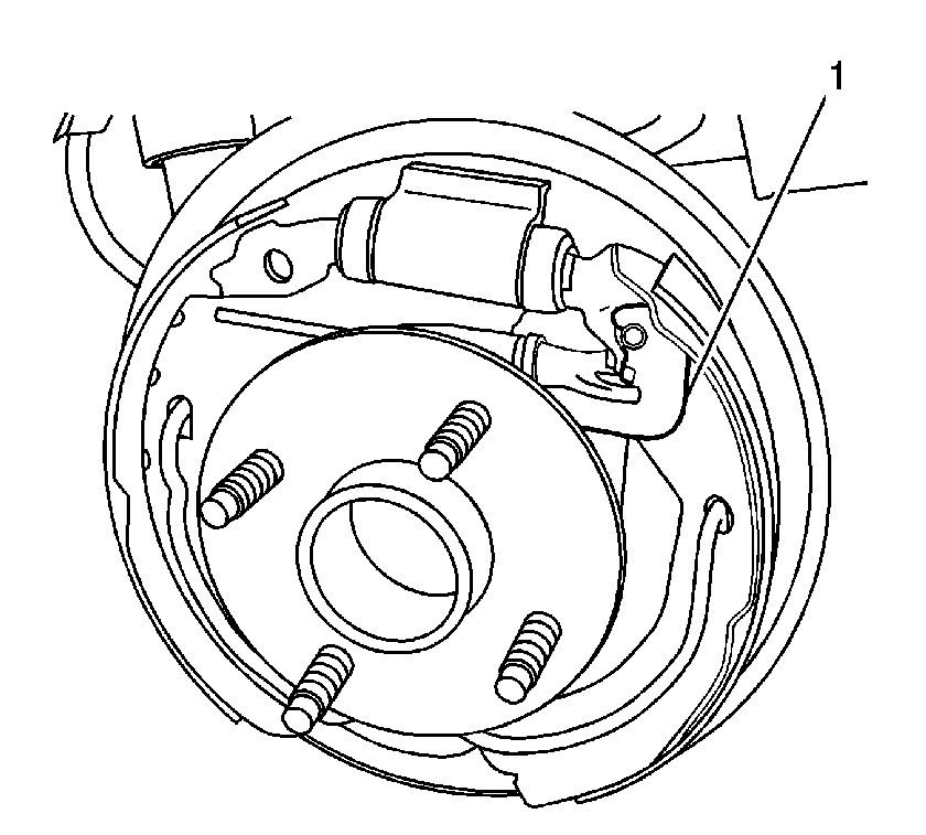
- Remove the adjuster actuator lever (1) from the pivot.
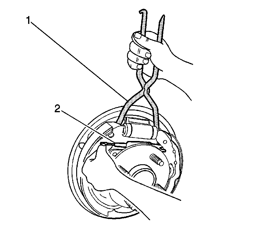
- Using the J 38400 (1), spread the top of the brake shoes apart.
- Remove the adjuster assembly (2) from the brake shoes.
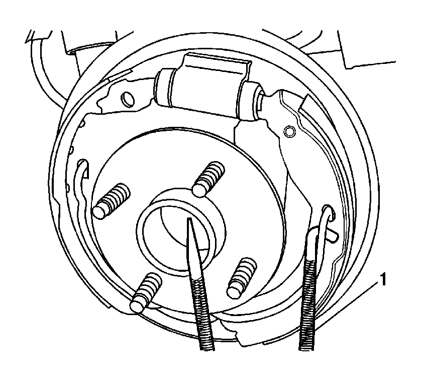
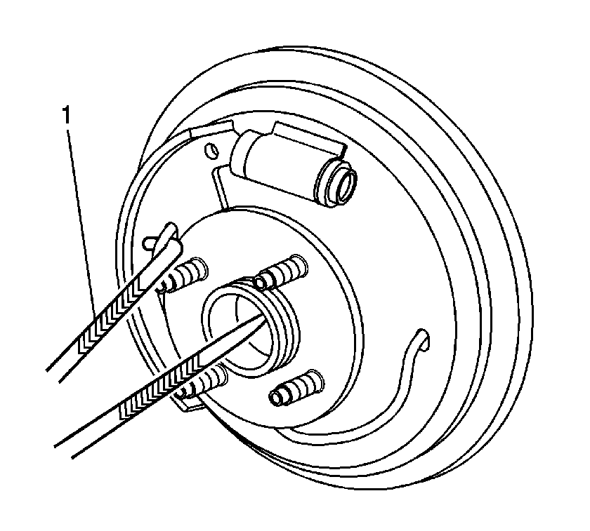
- Position the hook end of the J 38400 (1) under the universal spring and lightly pull the universal spring end out of the shoe web hole. Hold the universal spring while removing the trailing brake shoe.
- Release the park brake cable from the park brake lever on the trailing shoe.
- Position the hook end of the J 38400 (1) under the universal spring and lightly pull the universal spring end out of the shoe web hole. Hold the universal spring while removing the leading brake shoe.
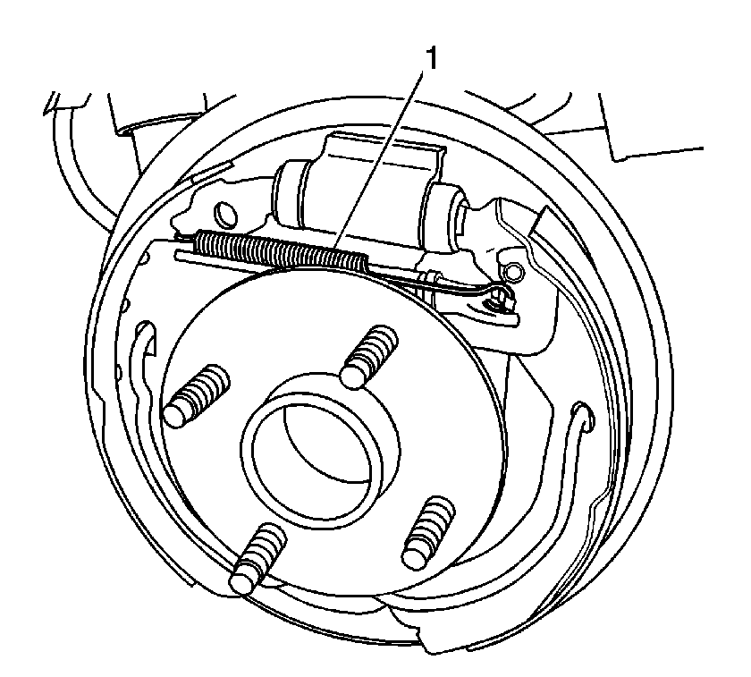
Notice: Do not over stretch the adjuster spring. Damage can occur if the spring is over stretched.
Installation Procedure
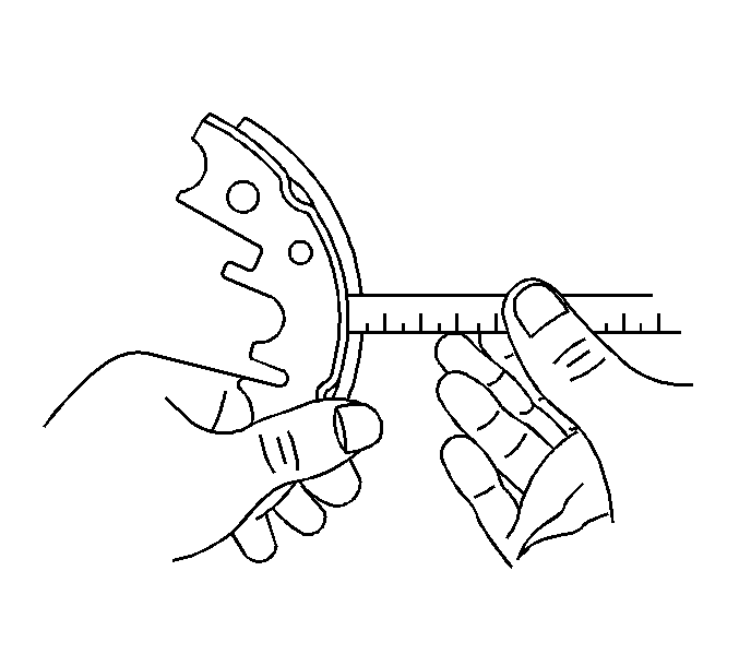
- Measure the brake shoe lining thickness.
- If the brake shoe lining thickness is at or below the minimum specification, replace the brake shoes.
- Apply a thin, light coat of high temperature silicone brake lubricant to the brake shoe contact surfaces of the brake backing plate.
- Position the hook end of the J 38400 (1) under the universal spring and lightly pull the universal spring end out while installing the leading brake shoe. Ensure that the universal spring engages the brake shoe web hole.
- Install the park brake cable to the park brake lever on the trailing brake shoe.
- Position the hook end of the J 38400 (1) under the universal spring and lightly pull the universal spring end out while installing the trailing brake shoe. Ensure that the universal spring properly engages the brake shoe web hole.
- Using the J 38400 (1), spread the top of the brake shoes apart.
- Install the adjuster assembly (2) to the brake shoes.
- Install the adjuster actuator lever (1) to the brake shoe and the adjuster assembly. Ensure that the lever is properly engaged between the adjuster assembly and the brake shoe.
- Install the adjuster spring (1). Ensure that the loop end of the spring fully engages the tab on the actuator lever.
- Adjust the drum brakes. Refer to Drum Brake Adjustment .
- Install the brake drum. Refer to Brake Drum Replacement .
- Install the tire and wheel assembly. Refer to Tire and Wheel Removal and Installation .
- Lower the vehicle.
Specification
Brake Shoe Lining Minimum Thickness: 0.5 mm (0.020 in).


Notice: Do not over stretch the adjuster spring. Damage can occur if the spring is over stretched.
