For 1990-2009 cars only
Special Tools
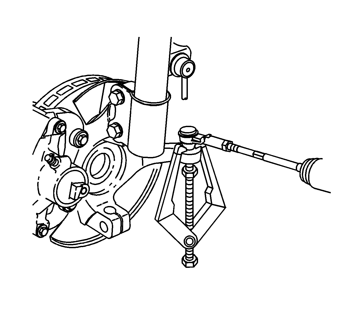
J 24319-B Steering Linkage and Tie Rod Puller
Removal Procedure
- Remove the front tire/wheel. Refer to Tire and Wheel Removal and Installation.
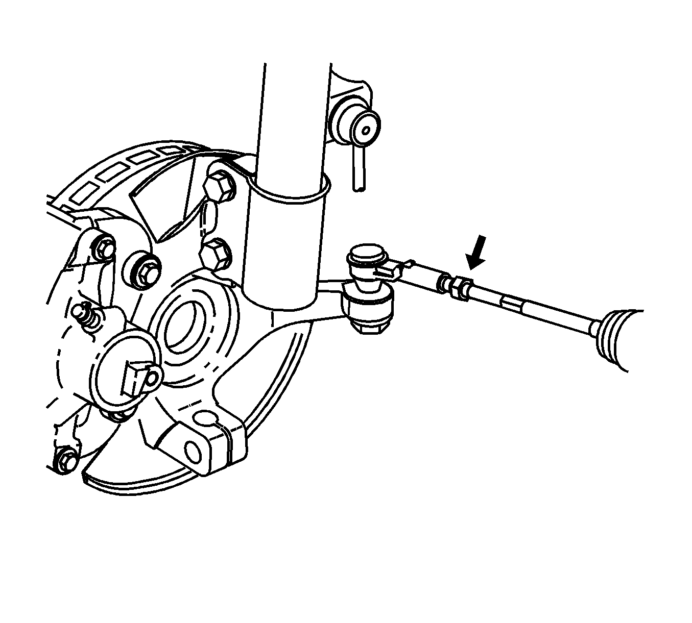
- Loosen the rack and pinion inner tie rod nut.
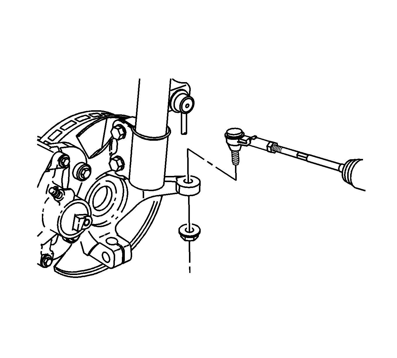
- Remove the rack and pinion outer tie rod end nut and discard it.
- Use puller J 24319-B to separate the rack and pinion outer tie rod end from the steering knuckle.
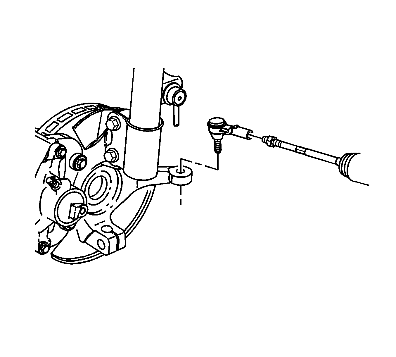
- Remove the rack and pinion outer tie rod end from the rack and pinion inner tie rod.
- Remove the rack and pinion inner tie rod nut and discard it.


Note: Count the total number of complete rotations needed to remove the rack and pinion outer tie rod end from the rack and pinion inner tie rod.
Installation Procedure
- Install a rack and pinion inner tie rod nut.
- Thread the rack and pinion outer tie rod end onto the rack and pinion inner tie rod.
- Install the rack and pinion outer tie rod end to the steering knuckle.
- Install a new rack and pinion outer tie rod end nut.
- Tighten the rack and pinion inner tie rod nut.
- Install the front tire/wheel. Refer to Tire and Wheel Removal and Installation.
- Adjust the front toe. Refer to Wheel Alignment - Steering Wheel Angle and/or Front Toe Adjustment.

Note: Inspect the rack and pinion inner tie rod threads for any damage or debris. Clean, repair, or replace the rack and pinion inner tie rod as needed.

Note: Install the rack and pinion outer tie rod end the same number of complete rotations counted when removing it prior.

Caution: Refer to Fastener Caution in the Preface section.
Tighten
Tighten the nut to 25 N·m (18 lb ft) plus 90 degrees.
