Steering Gear Replacement Electronic Power Steering (EPS)
Removal Procedure
- Turn the steering wheel to the straight forward position, support it from movement, and remove the key from the ignition.
- Raise and support the vehicle. Refer to Lifting and Jacking the Vehicle .
- Remove the front tires and wheels. Refer to Tire and Wheel Removal and Installation .
- Remove the intermediate shaft to steering gear pinch bolt. Discard the bolt.
- Separate the intermediate shaft from the steering gear.
- Remove the tie rod end castle nuts.
- Using the J 24319-B , separate the tie rod ends from the steering knuckles.
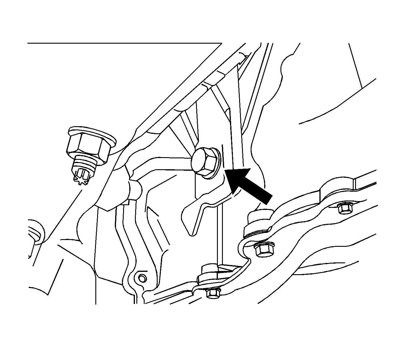
- Remove the rear transmission mount-to-transmission bolt.
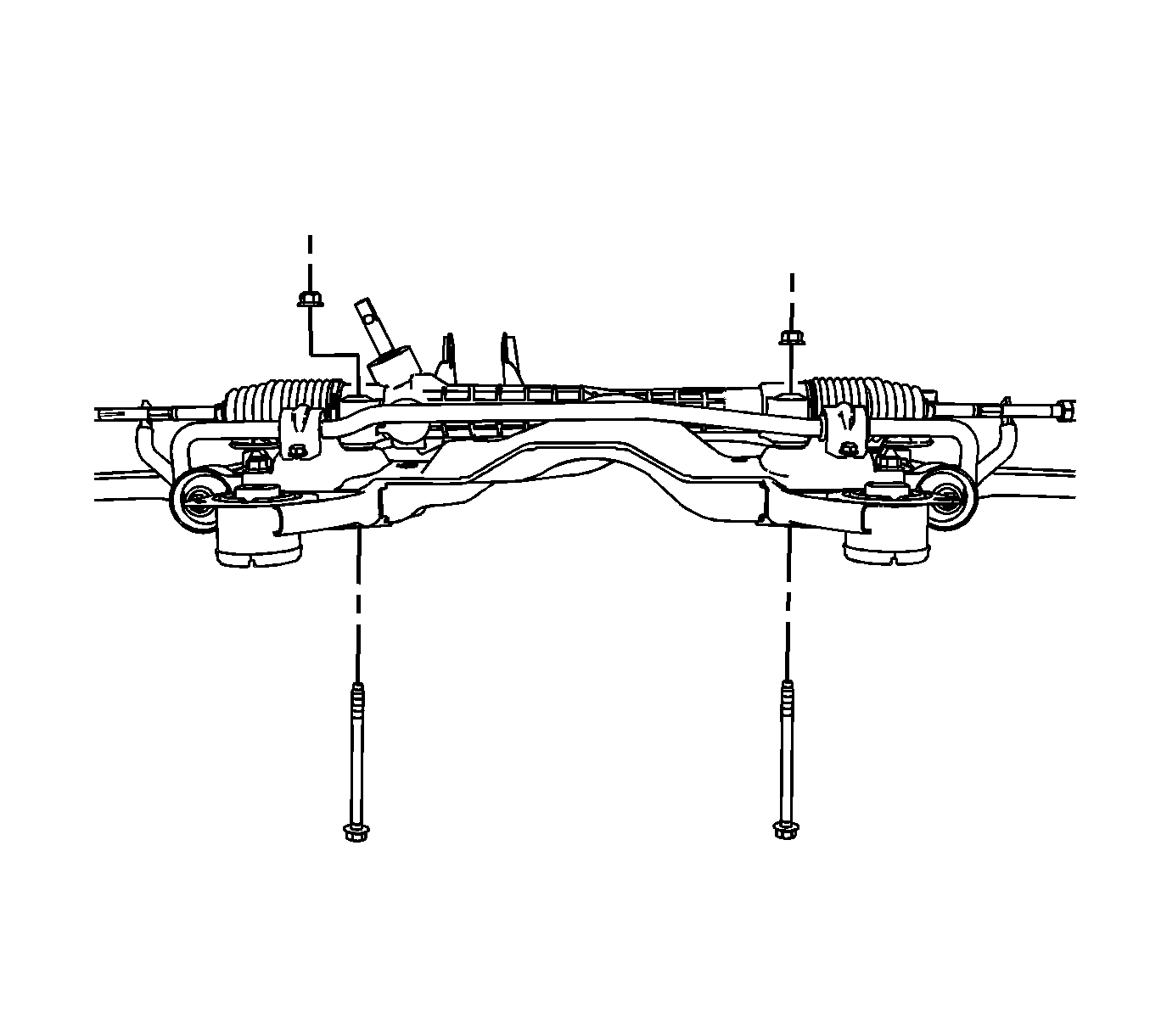
- Remove the steering gear to frame bolts.
- Remove the steering gear through the left side of the vehicle. Rotate the gear 90 degrees in order to clear the rear transmission mount.
- If replacing the steering gear, remove the outer tie rod ends. Refer to Rack and Pinion Outer Tie Rod End Replacement .
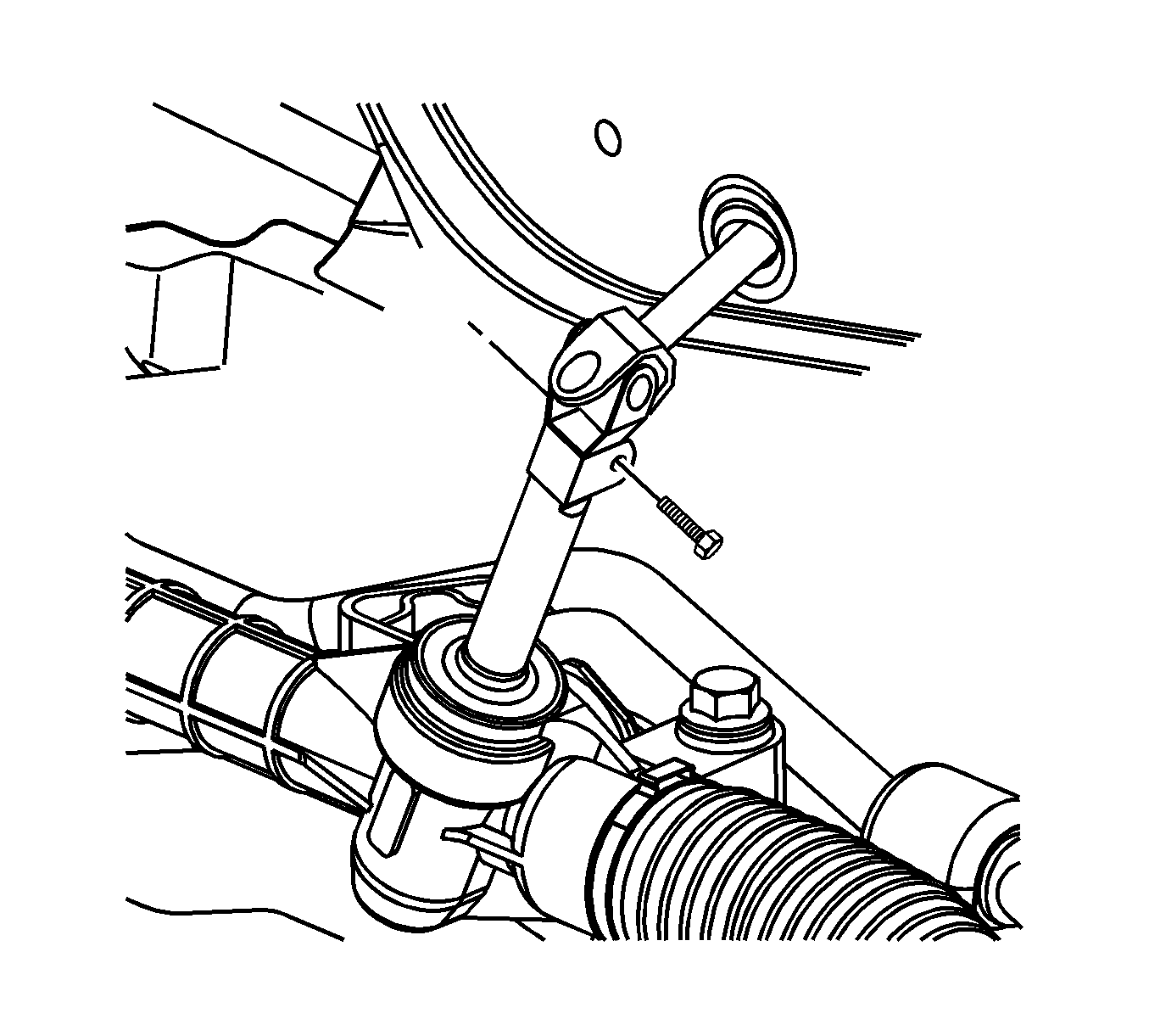
Important: Secure the steering wheel in the straight forward position before separating the intermediate shaft from the steering gear, or damage to the SIR coil will occur.
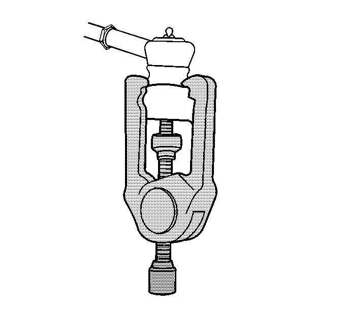
Notice: Do not free the ball stud by using a pickle fork or a wedge-type tool. Damage to the seal or bushing may result.
Installation Procedure
- Install the outer tie rod ends to the steering gear. Refer to Rack and Pinion Outer Tie Rod End Replacement .
- Install the steering gear to the vehicle. Rotate the gear as necessary to clear the rear transmission mount.
- Install the steering gear to frame bolts.
- Install the rear transmission mount-to-transmission bolt.
- Connect the intermediate steering shaft to the steering gear as noted during removal.
- Install the new intermediate steering shaft to steering gear pinch bolt.
- Position the outer tie rod ends into the steering knuckles.
- Install new torque castle nuts to the tie rod end ball studs.
- Install the front tires and wheels. Refer to Tire and Wheel Removal and Installation .
- Lower the vehicle.
- Measure the wheel alignment and adjust as necessary. Refer to Wheel Alignment Measurement .

Notice: Refer to Fastener Notice in the Preface section.
Tighten
Tighten the bolts to 70 N·m (52 lb ft) plus an additional 90 degrees.

Tighten
Tighten the bolt to 90 N·m (66 lb ft).

Tighten
Tighten the bolt to 49 N·m (36 lb ft).
Important: Hold the ball stud from turning during installation of the castle nut.
Tighten
Tighten the castle nuts to 25 N·m (18 lb ft) plus 90 degrees.
Steering Gear Replacement Hydraulic Power Steering (LX9, LZ9)
Tools Required
J 24319-B Universal Steering Linkage and Tie Rod Puller
Removal Procedure
- Turn the steering wheel to the straight forward position, support it from movement, and remove the key from the ignition.
- Raise and support the vehicle. Refer to Lifting and Jacking the Vehicle .
- Remove the front tires and wheels. Refer to Tire and Wheel Removal and Installation .
- Remove the tie rod end castle nuts.
- Using the J 24319-B , separate the tie rod ends from the steering knuckles.
- Remove the intermediate shaft to steering gear pinch bolt (1). Discard the bolt.
- Separate the intermediate shaft (2) from the steering gear (3).
- Loosen the transaxle mount through bolt.
- Disconnect the heated oxygen sensor (HO2S) electrical connector.
- Disconnect the HO2S sensor harness from the transmission mount bracket.
- Remove the 3 transaxle mount to transaxle bolts.
- Remove the 3 transaxle bracket to cradle/frame nuts.
- Position the transaxle bracket and rear mount aside.
- Remove the bolt (1) and disconnect the power steering gear inlet (2) and outlet (4) pipe/hoses from the power steering gear (3). Cap off the pipe/hoses and position aside.
- Remove the power steering gear outlet pipe routing pin-style retainer from the RH rear side of the cradle/frame.
- Convertible vehicles, support the rear of the cradle/frame with a suitable jack stand.
- Convertible vehicles, remove the rear cradle/frame mount bolts.
- Remove the power steering gear mounting bolts, nuts, and washers from the gear.
- Remove the power steering gear through the LH wheel opening.
- If the power steering gear is to be replaced, transfer the outer tie rod ends to the new steering gear.

Notice: Do not free the ball stud by using a pickle fork or a wedge-type tool. Damage to the seal or bushing may result.
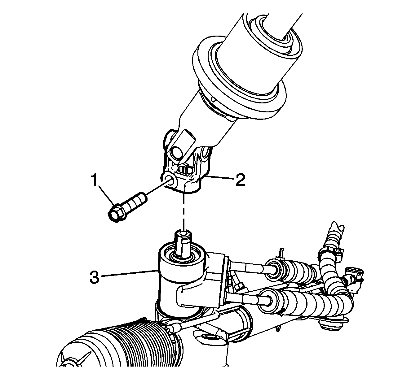
Important: Secure the steering wheel in the straight forward position before separating the intermediate shaft from the steering gear, or damage to the SIR coil will occur.
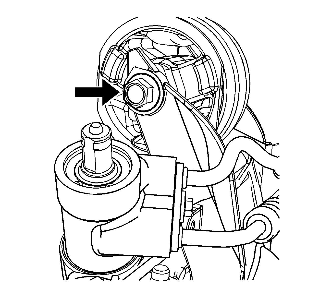
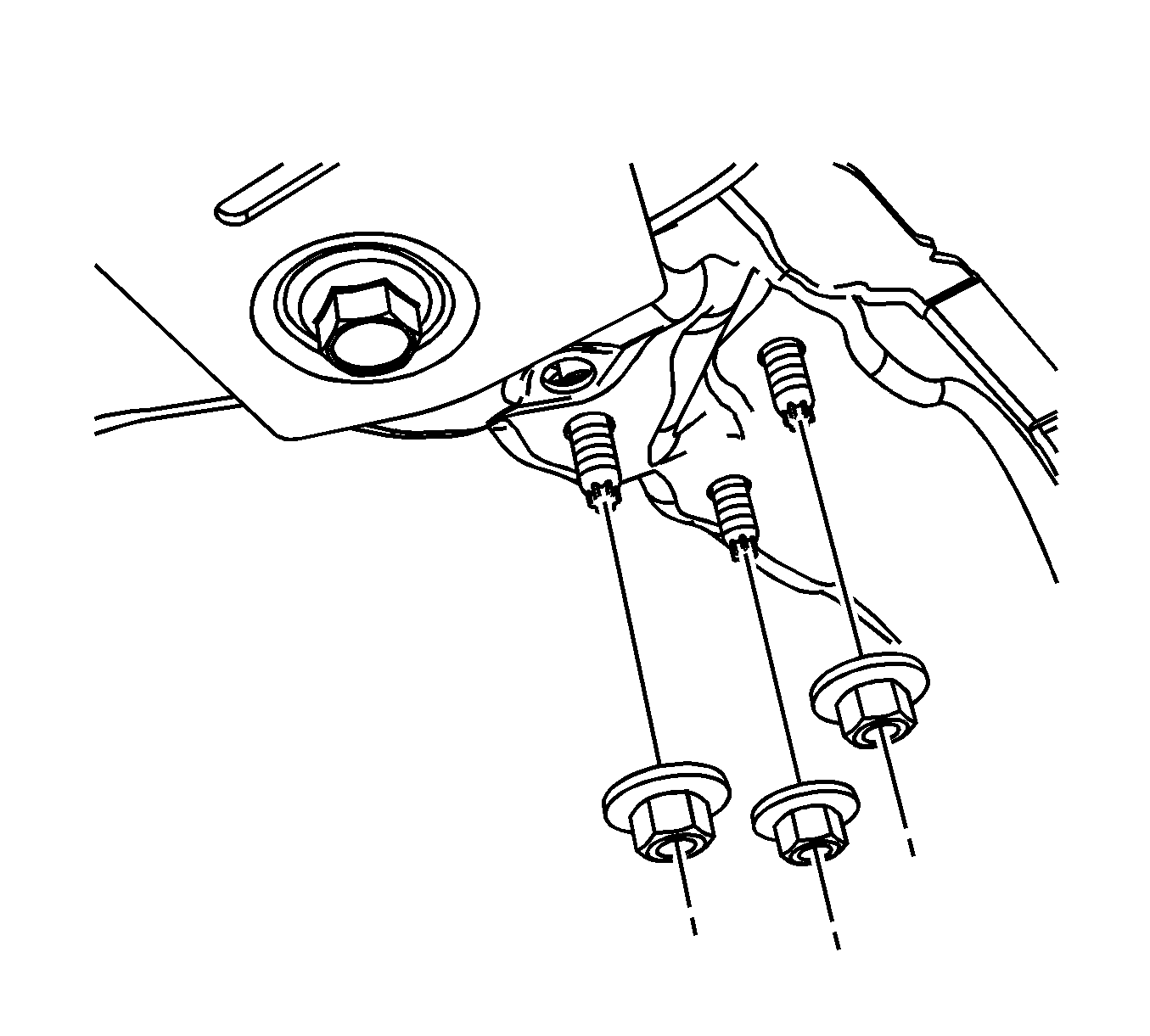
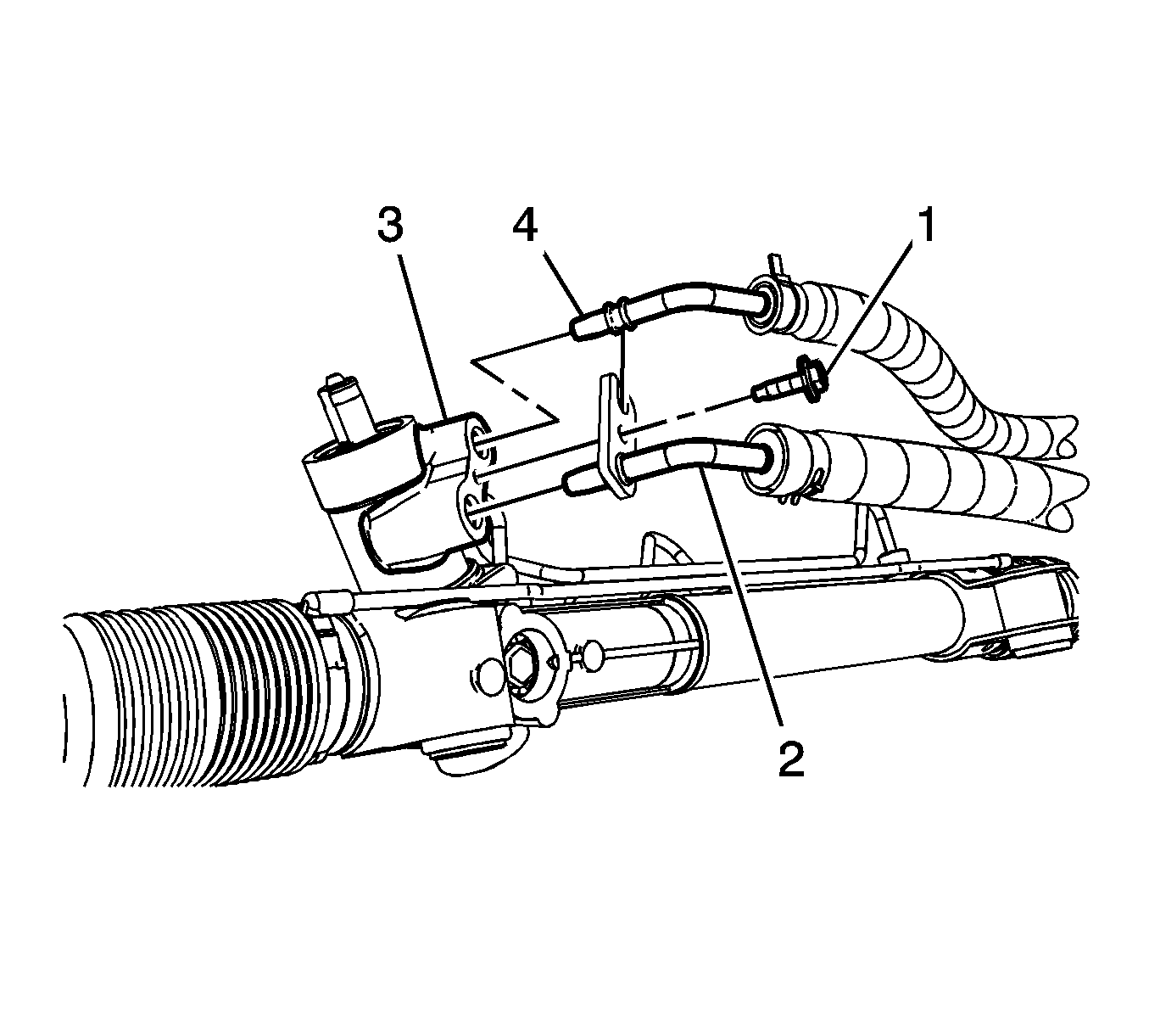
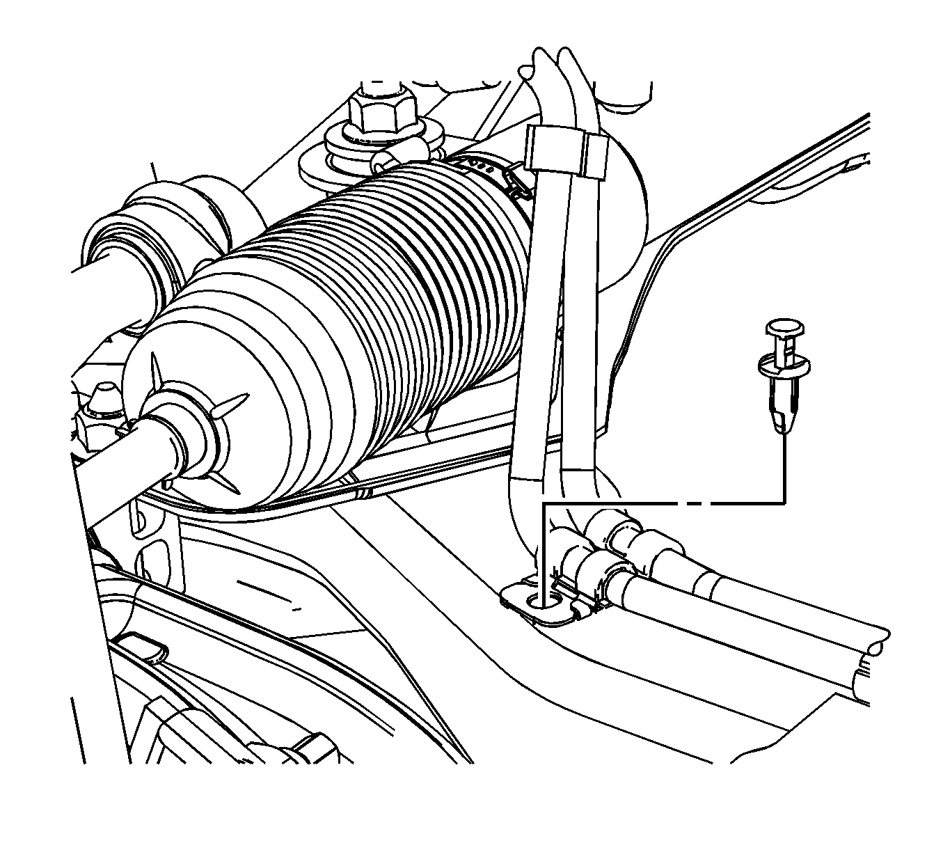
Important: Convertible vehicles utilize a cross brace that is installed by sharing the cradle/frame mounting bolts. With the rear cradle frame bolts removed, it allows the cross brace to have movement to gain access to the power steering gear mounting bolts.
Important: The power steering gear will need to be rotated while it is removed through the LH wheel opening.
Installation Procedure
- Position the power steering gear into the vehicle.
- Connect the intermediate steering shaft to the steering gear.
- Install the power steering gear mounting bolts, nuts and washers to the power steering gear.
- Convertible vehicles, install the rear cradle/frame mounting bolts.
- Convertible vehicles, remove the jack stand.
- Install the power steering gear outlet pipe routing pin-style retainer to the RH rear side of the cradle/frame.
- Connect the power steering gear inlet (2) and outlet (4) pipe/hoses to the power steering gear (3) and install the bolt (1).
- Install the new intermediate steering shaft to steering gear pinch bolt (1).
- Position the transaxle bracket and rear mount back to their original position.
- Install the 3 transaxle bracket to cradle/frame nuts.
- Install the 3 transaxle mount to transaxle bolts.
- Connect the HO2S sensor harness to the transmission mount bracket.
- Connect the heated oxygen sensor (HO2S) electrical connector.
- Tighten the transaxle mount through bolt.
- Position the outer tie rod ends into the steering knuckles.
- Install new torque castle nuts to the tie rod end ball studs.
- Install the front tires and wheels. Refer to Tire and Wheel Removal and Installation .
- Lower the vehicle.
- Fill and bleed the power steering system. Refer to Power Steering System Bleeding .
- Measure the wheel alignment and adjust as necessary. Refer to Wheel Alignment Measurement .
Important: The power steering gear will need to be rotated while it is installed through the LH wheel opening.
Notice: Refer to Fastener Notice in the Preface section.
Tighten
Tighten the mounting bolts, nuts to 110 N·m (81 lb ft).
Tighten
Tighten the rear cradle/frame mounting bolts to 100 N·m (73 lb ft) plus 180 degree rotation.


Tighten
Tighten the pipe/hose to power steering gear bolt to 27 N·m (20 lb ft).

Tighten
Tighten the pinch bolt to 49 N·m (36 lb ft).

Tighten
Tighten the transaxle bracket to cradle/frame nuts to 50 N·m (37 lb ft).
Tighten
| • | LZ4 Engines: Tighten the transaxle mount bolts to 90 N·m (66 lb ft). |
| • | LZ9 Engines: Tighten the transaxle mount bolts to 50 N·m (37 lb ft). |

Tighten
| • | LZ4 Engines: Tighten the transaxle mount bolts to 90 N·m (66 lb ft). |
| • | LZ9 Engines: Tighten the transaxle mount bolts to 50 N·m (37 lb ft). |
Important: Hold the ball stud from turning during installation of the castle nut.
Tighten
Tighten the castle nuts to 25 N·m (18 lb ft) plus 90 degrees.
