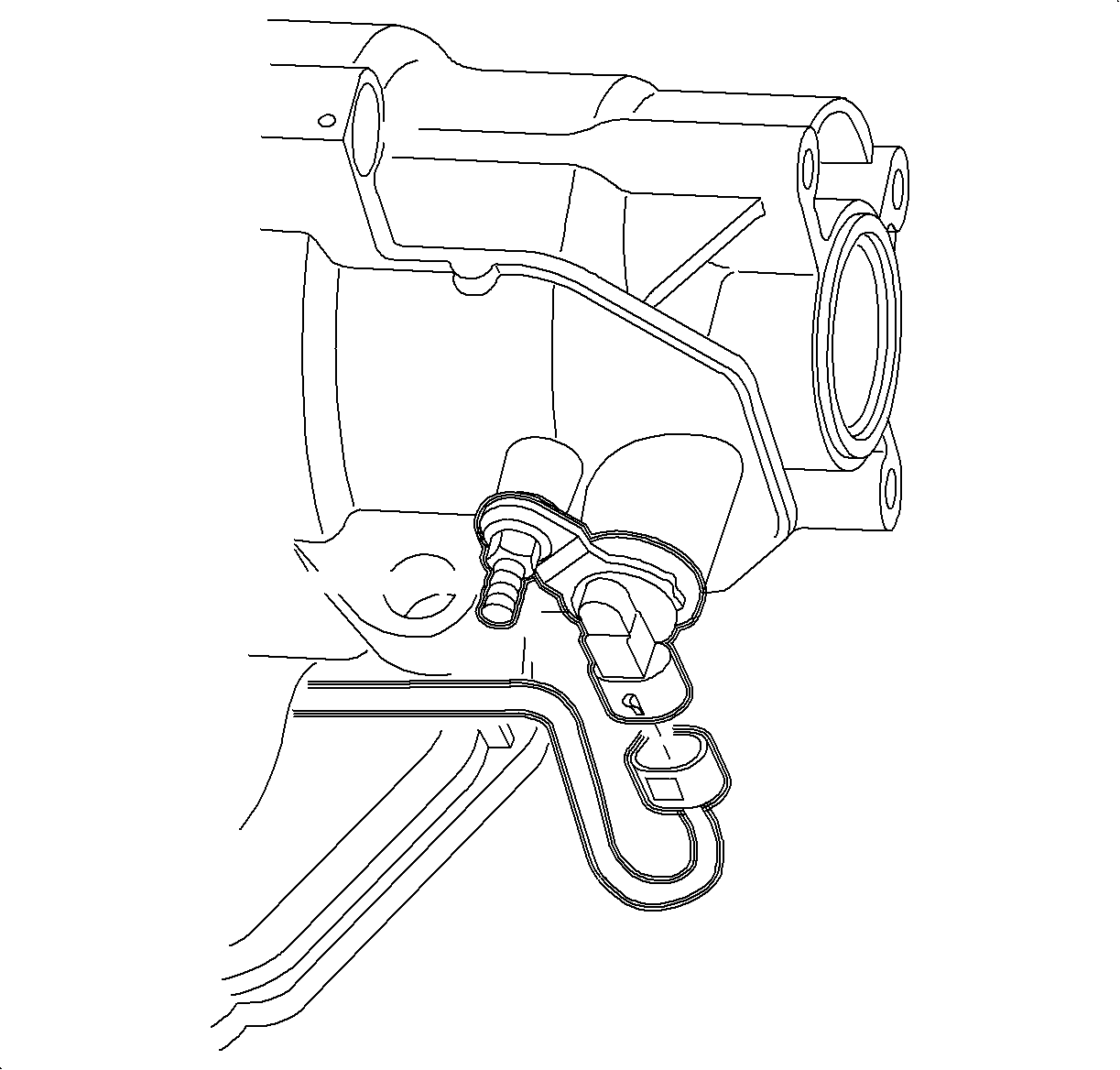
For 1990-2009 cars only
Removal Procedure
- Position the vehicle on a hoist and raise the vehicle. Refer to Lifting and Jacking the Vehicle .
- Disconnect the vehicle speed sensor (VSS) electrical connector.
- Remove the VSS electrical harness retainer from the VSS stud.
- Remove the VSS stud.
- Remove the output VSS from the transmission case.
- Remove the O-ring from the VSS.

Caution: Ensure that the vehicle is properly supported and squarely positioned. To help avoid personal injury when a vehicle is on a hoist, provide additional support for the vehicle on the opposite end from which the components are being removed.
Important: Inspect the O-ring for damage and replace if necessary.
Installation Procedure
- Install the O-ring onto the VSS.
- Install the output VSS into the transmission case.
- Install the VSS stud.
- Install the VSS electrical harness retainer to the VSS stud.
- Connect the VSS electrical connector.
- Lower the vehicle.

Notice: Refer to Fastener Notice in the Preface section.
Tighten
Tighten the stud to 12 N·m (106 lb in).
