For 1990-2009 cars only
Removal Procedure
- Remove the instrument panel (I/P) cluster. Refer to Instrument Cluster Replacement .
- Remove the knee bolster. Refer to Knee Bolster Replacement .
- Remove the I/P center trim panel. Refer to Instrument Panel Center Trim Panel Replacement .
- Remove the ignition switch wire harness connector.
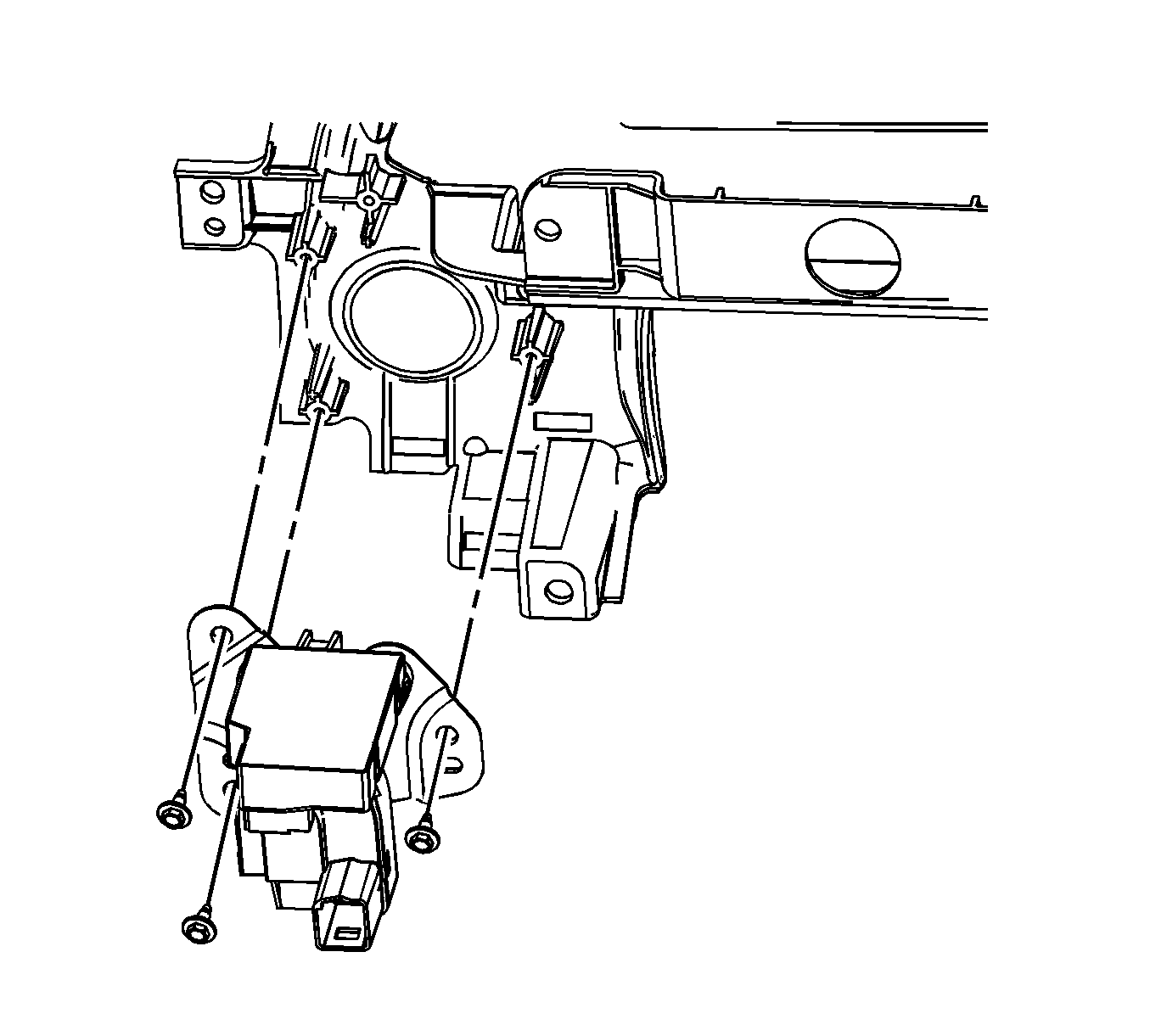
- Remove the theft deterrent module wire harness connector.
- Remove the ignition switch lock cylinder. Refer to Ignition Switch Lock Cylinder Replacement .
- Disconnect the park lock cable at the ignition switch. Refer to the appropriate procedure:
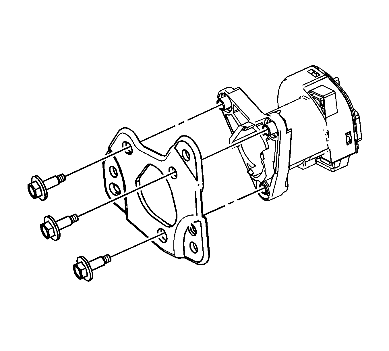
- Remove the ignition switch at the I/P screws.
- Remove the ignition switch assembly.
- Remove the ignition switch bracket screws.
- Remove the theft deterrent module. Refer to Theft Deterrent Module Replacement .
- Remove the ignition switch bracket.
| • | Park Lock Cable Replacement for the 4T40-E/4T45-E transaxle |
| • | Park Lock Cable Replacement for the 4T65-E transaxle |
| • | Park Lock Cable Replacement for the F40 transmission |


Installation Procedure
- Install the ignition switch bracket.
- Install the theft deterrent module. Refer to Theft Deterrent Module Replacement .
- Install the ignition switch bracket screws.
- Install the ignition switch .
- Tighten the ignition switch screws.
- Connect the park lock cable at the ignition switch. Refer to the appropriate procedure:
- Install the theft deterrent module wire harness connector.
- Install the ignition switch wire harness connector.
- Install the ignition switch lock cylinder. Refer to Ignition Switch Lock Cylinder Replacement .
- Install the I/P center trim panel. Refer to Instrument Panel Center Trim Panel Replacement .
- Install the knee bolster. Refer to Knee Bolster Replacement .
- Install the I/P cluster. Refer to Instrument Cluster Replacement .

Notice: Refer to Fastener Notice in the Preface section.
Tighten
Tighten the screws to 5 N·m (44 lb in).

Tighten
Tighten the screws to 2.5 N·m (22 lb in).
| • | Park Lock Cable Replacement for the 4T40-E/4T45-E transaxle |
| • | Park Lock Cable Replacement for the 4T65-E transaxle |
| • | Park Lock Cable Replacement for the F40 transmission |
