Folding Top Pump with Motor Replacement Pump
Removal Procedure
- Place the folding top in the fully closed position.
- Open the rear compartment.
- Disconnect the battery. Refer to Battery Negative Cable Disconnection and Connection .
- Place a protective covering over the rear compartment interior and the adjacent body panels.
- Remove the right side compartment trim. Refer to Rear Compartment Side Trim Replacement - Right Side .
- Disconnect the folding top motor solenoid harness.
- Release the hydraulic pump pressure. Refer to Folding Top Pump Bypass Valve Pressure Release Adjustment .
- Remove the 2 nuts that attach the control module to the pump bracket. Refer to Folding Top Control Module Replacement .
- Remove the electrical connectors from the pump bracket and control module.
- Remove the nuts (2) that attach the pump to the floor pan.
- Remove the screws (1) from the pump manifold (3).
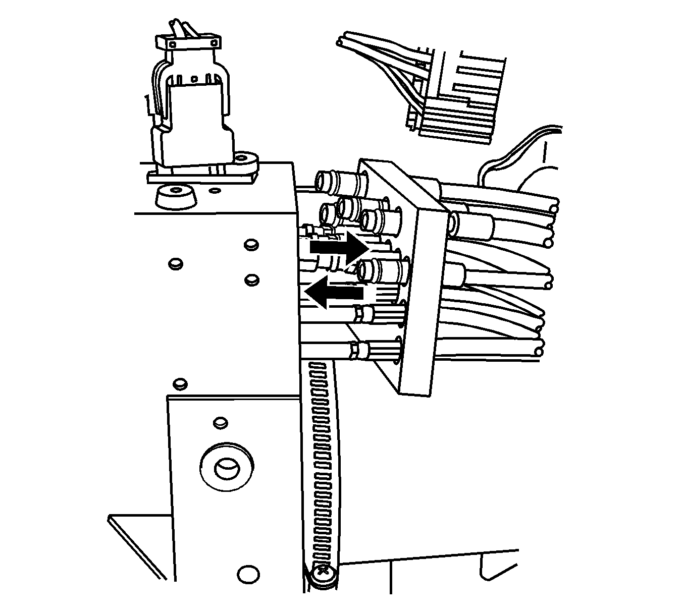
- Disengage the cylinder hoses (1) by pulling straight rearward on the manifold block and hoses (2).
- Lift the pump upward to disconnect the electrical connector from the hydraulic pump motor.
- Lift the pump up and out of the storage compartment and set the pump on the a protective cover.
- Remove the reservoir filler plug (1).
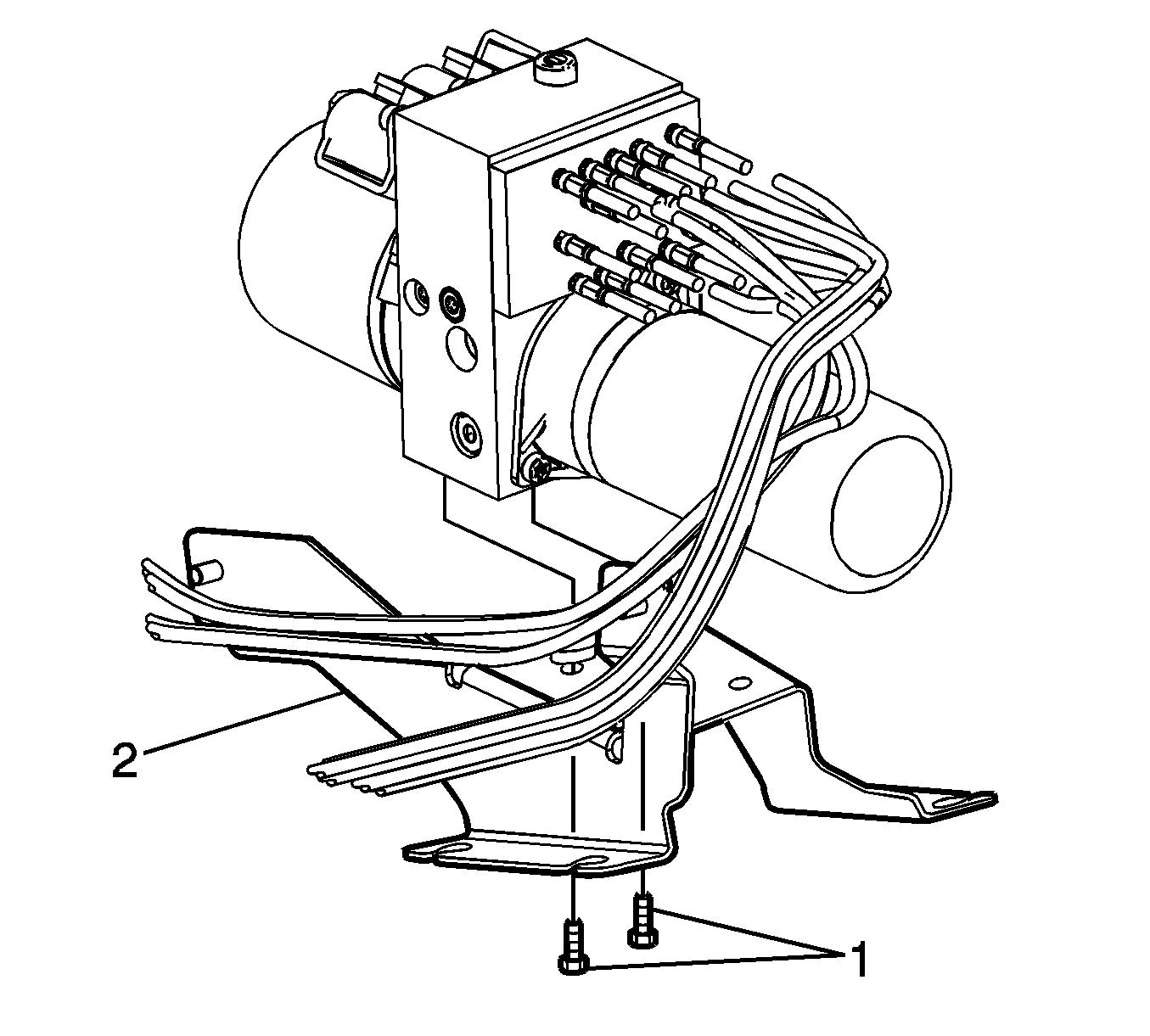
- Remove the screws (1) from the pump bracket (2).
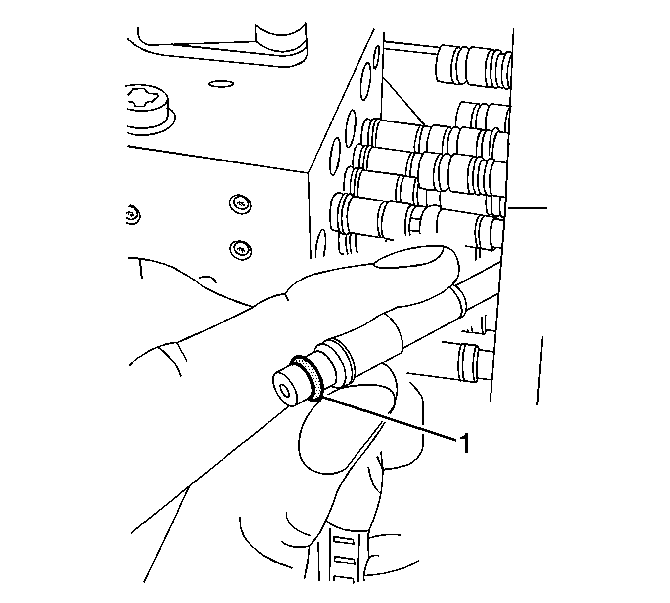
- Remove the O-ring (1) from each hose.
Caution: Refer to Eye Protection Caution in the Preface section.
Caution: Refer to Folding Top Hydraulic Pressure Caution in the Preface section.
Caution: Refer to Servicing Electrical Components Caution in the Preface section.
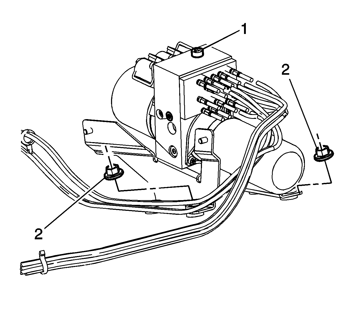
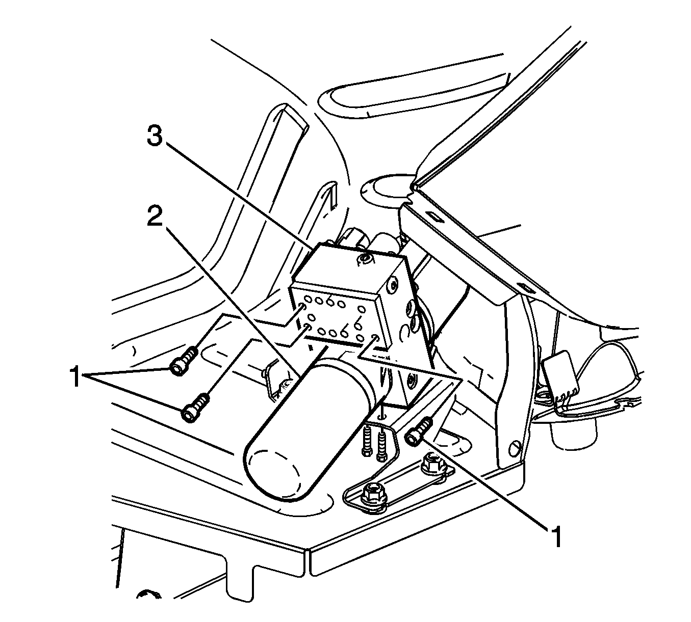
Important: Rotate the pump motor outward to remove the bolts from the hydraulic line manifold.
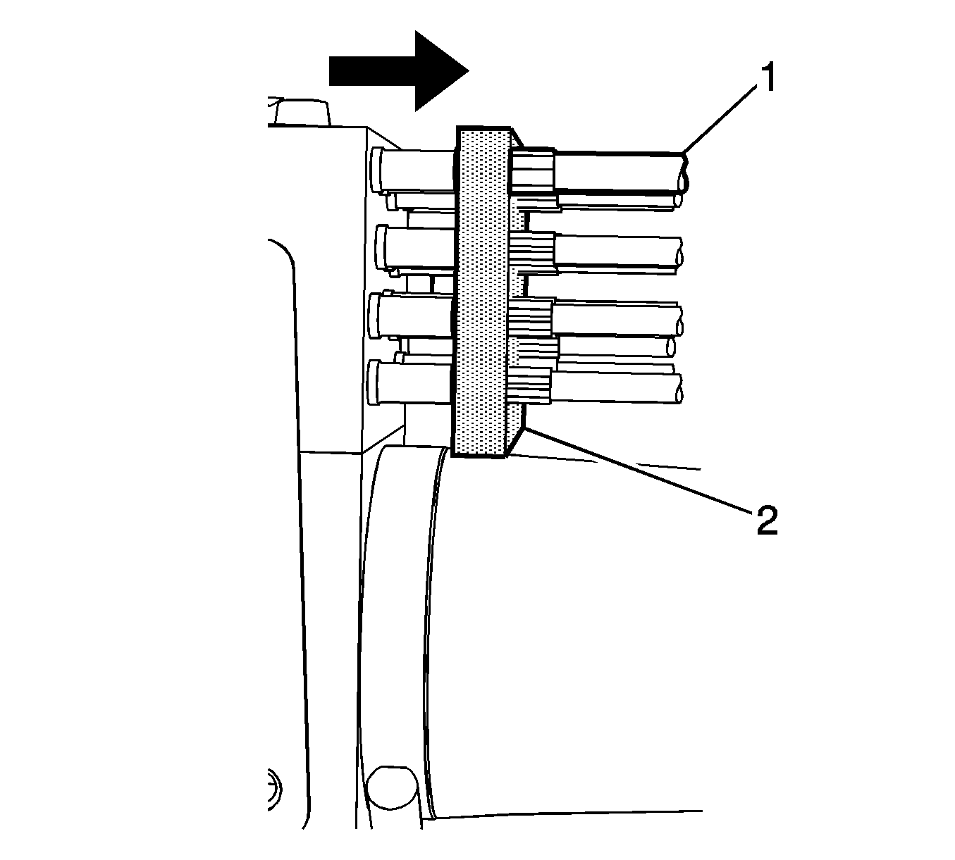
Use a clean shop towel to control any hydraulic fluid leakage.
Use a clean covered surface to control any hydraulic fluid leakage.
Empty the hydraulic fluid in to a suitable container, when replacing the pump motor.
Installation Procedure
- Install the screws (1) to the hydraulic pump bracket (2) and the screws to the motor.
- Install a new O-ring (1) on each cylinder hose.
- Install the pump to the storage compartment and set the pump on the a protective covering.
- Align the manifold plate bolt holes to the holes on the new pump. This will ensure that the cylinder hoses are placed in the correct port.
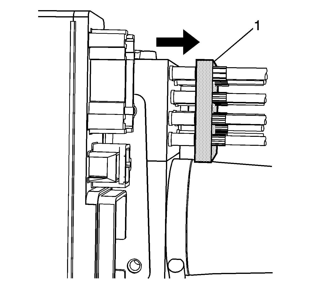
- Align the cylinder hoses into each port and push down until the hoses are seated properly in the hydraulic pump manifold.
- Push down on the manifold plate (1) and verify that all of the cylinder hoses are seated properly.
- Connect the electrical connectors to the hydraulic pump.
- Install the nuts that attach the pump to the floor pan.
- Connect the folding top pump solenoid harness.
- Connect the electrical connectors to the control module.
- Install the 2 nuts that attach the control module to the pump bracket.
- Add fluid as needed. Refer to Folding Top Fluid Addition .
- Install the reservoir filler plug.
- Remove the protective covering.
- Close the pump bypass valve (1). Refer to Folding Top Pump Bypass Valve Pressure Release Adjustment .
- Connect the battery. Refer to Battery Negative Cable Disconnection and Connection .
- Bleed the hydraulic system. Refer to Folding Top Hydraulic System Bleeding Procedure .
- Inspect the hydraulic system for fluid leaks.
- Inspect the hydraulic system fluid level and add fluid as needed. Refer to Folding Top Fluid Addition .
- Install the side compartment trim. Refer to Rear Compartment Side Trim Replacement - Right Side .
- Close the rear compartment.
- Inspect the folding top for proper operation.
Notice: Refer to Fastener Notice in the Preface section.

Tighten
Tighten the screws to 10 N·m (89 lb in).

Use a clean shop towel to control any hydraulic fluid leakage.
Tighten
Tighten the bolts to 10 N·m (89 lb in).
Apply LOCTITE® Blue, GM P/N 12345382 (Canadian P/N 10953489) or equivalent to the bolts.
Tighten
Tighten the bolts to 18 N·m (13 lb ft).
Tighten
Tighten the nuts to 18 N·m (13 lb ft).

Folding Top Pump with Motor Replacement Motor
Removal Procedure
- Place the folding top in the fully closed position.
- Open the rear compartment.
- Disconnect the battery. Refer to Battery Negative Cable Disconnection and Connection .
- Place a protective covering over the rear compartment interior and the adjacent body panels.
- Remove the right side compartment trim. Refer to Rear Compartment Side Trim Replacement - Right Side .
- Release the hydraulic pump pressure. Refer to Folding Top Pump Bypass Valve Pressure Release Adjustment .
- Remove the 2 nuts that attach the control module to the pump bracket.
- Remove the nuts (2) that attach the pump to the floor pan.
- Use a clean shop towel to control any hydraulic fluid leakage.
- Disconnect the electrical connector from the hydraulic pump.
- Stand the pump (3) and motor (2) upright to gain access to the pump motor screws (1).
- Remove the screws from the pump motor.
- Remove the motor from the pump assembly.
- Remove the pump propeller (1) from the motor (2).
Caution: Refer to Eye Protection Caution in the Preface section.
Caution: Refer to Folding Top Hydraulic Pressure Caution in the Preface section.
Caution: Refer to Servicing Electrical Components Caution in the Preface section.

Important: Do Not remove the pump completely from the storage compartment.
Important: When removing the motor it is NOT necessary to remove the hydraulic lines from the pump. The motor can be transfer from inside the storage compartment.
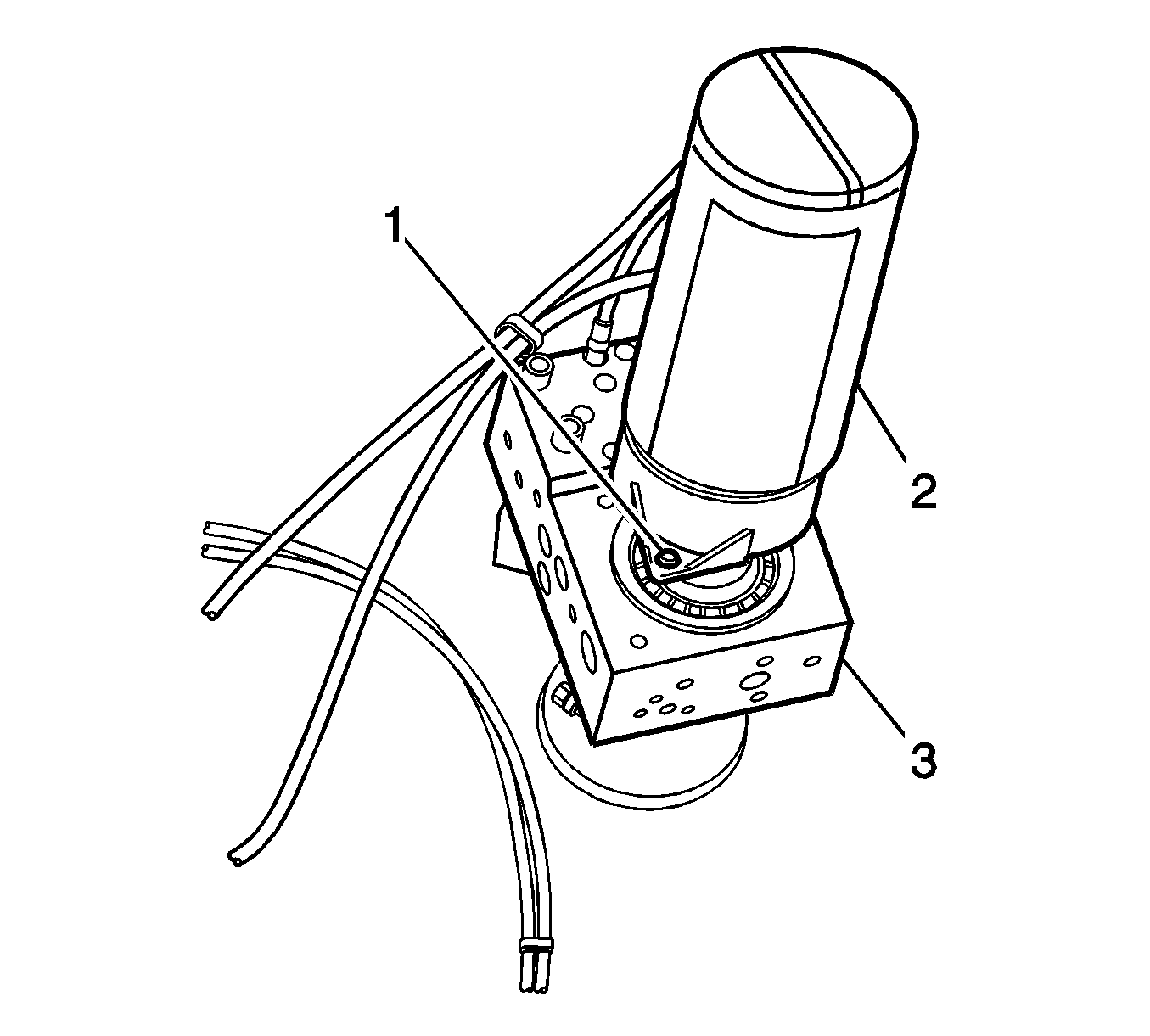
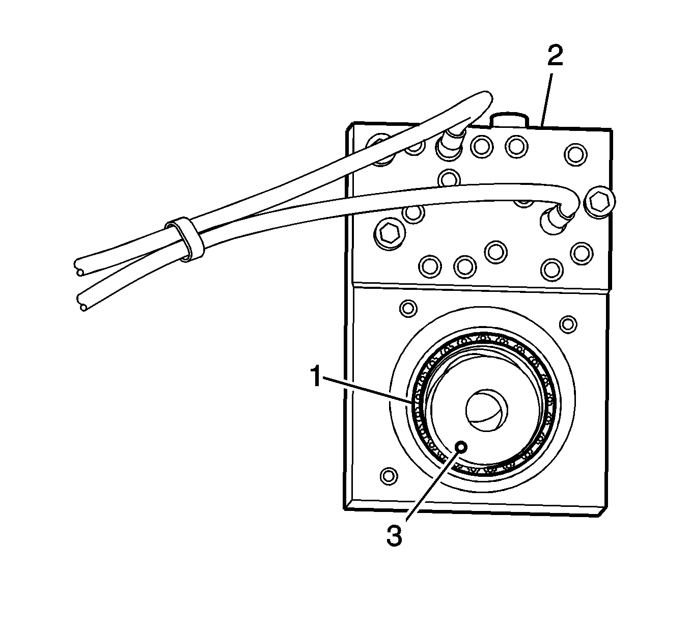
Important: Do Not let the pump propeller driver (1) separate from the pump (2) when pulling apart. If the pump propeller driver separates from the pump it is no longer serviceable and must be replaced.
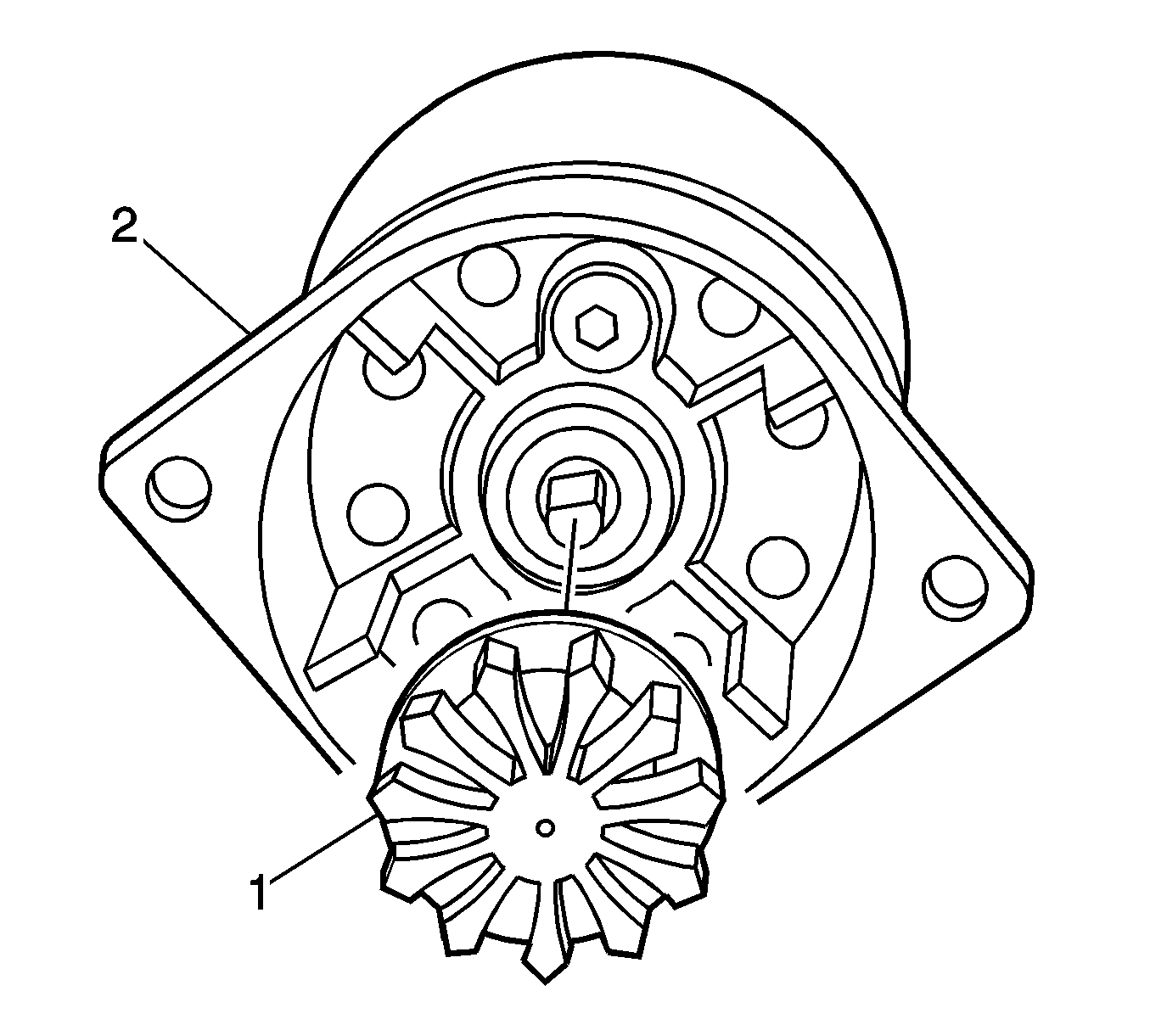
Installation Procedure
- Install the pump propeller (1) to the motor (2).
- Stand the pump (3) and motor (2) upright to gain access to the motor screws (1).
- Install the screws to the pump motor.
- Install the motor to the pump assembly.
- Connect the electrical connectors to the hydraulic pump.
- Install the nuts that attach the pump bracket to the floor pan.
- Install the 2 nuts that attach the control module to the pump bracket.
- Remove the protective covering from the rear compartment interior and the adjacent body panels.
- Tighten the hydraulic pump bypass valve (1). Refer to Folding Top Pump Bypass Valve Pressure Release Adjustment .
- Connect the battery. Refer to Battery Negative Cable Disconnection and Connection .
- Inspect the hydraulic system for leaks and fluid level. Refer to Folding Top Fluid Addition .
- Install the side compartment trim. Refer to Rear Compartment Side Trim Replacement - Right Side .
- Close the rear compartment.
- Inspect the folding top for proper operation.


Notice: Refer to Fastener Notice in the Preface section.
Tighten
Tighten the screws to 10 N·m (89 lb in).

Important: When reinstalling the pump motor propeller it must be in-line with the pump propeller driver (3).
Tighten
Tighten the bolts to 18 N·m (13 lb ft).

