Tools Required
J 45722 Fuel Sender Lock Ring Wrench
Removal Procedure
Caution: In order to reduce the risk of fire and personal injury that may result from a fuel leak, always replace the fuel sender gasket when reinstalling the fuel sender assembly.
- Remove the fuel tank. Refer to Fuel Tank Replacement.
- Disconnect the fuel pressure sensor and sender electrical connections.
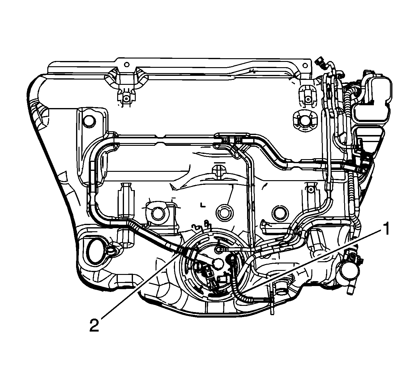
- Disconnect the EVAP vapor line quick connect fittings (1, 2). Refer to Plastic Collar Quick Connect Fitting Service.
- Disengage the fuel feed line from the retaining features built into the fuel tank.
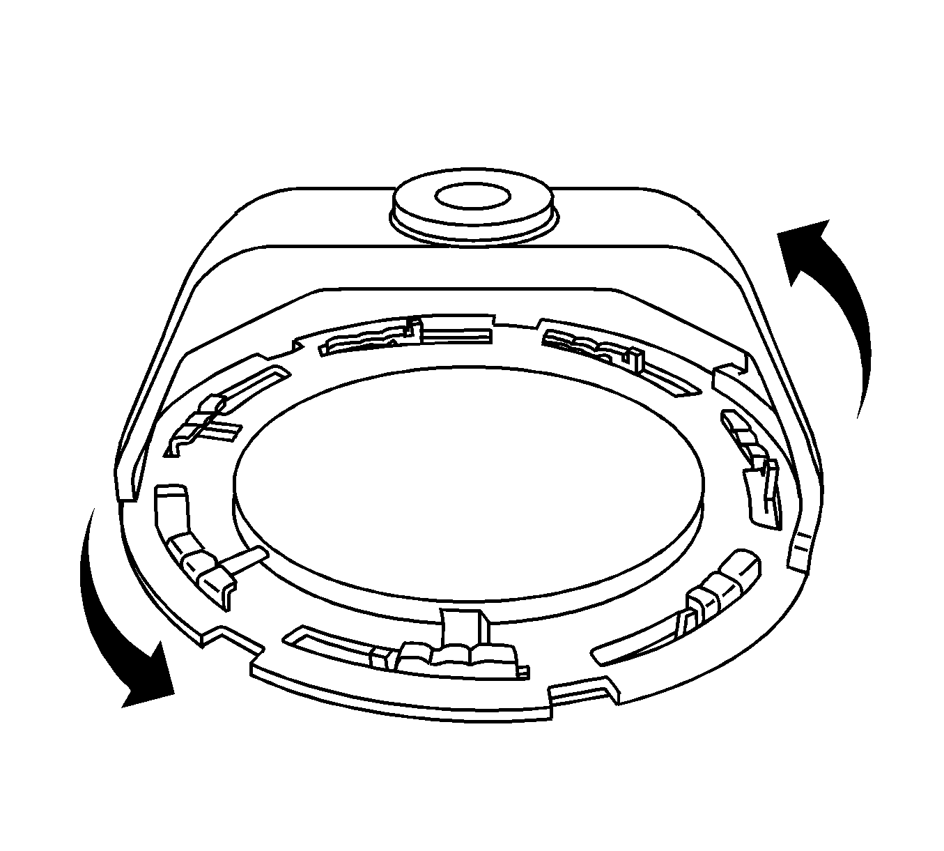
- Use the J 45722 and a long breaker-bar in order to unlock the fuel sender lock ring.
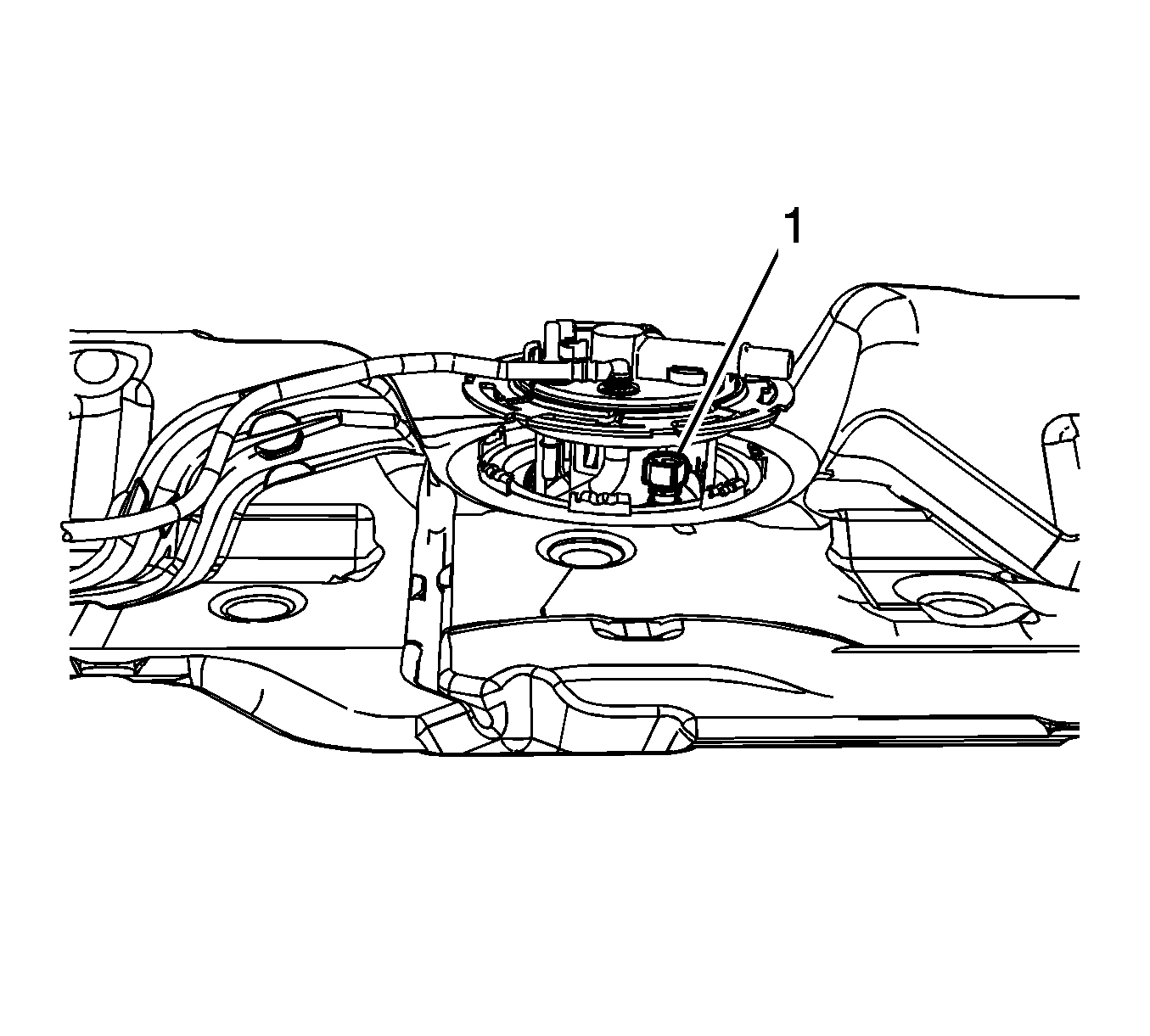
- Raise the fuel sender assembly out of the tank far enough to access the vapor line quick connect fitting (1) on the underside of the sender cover.
- Disconnect the vapor line quick connect fitting (1). Refer to Plastic Collar Quick Connect Fitting Service.
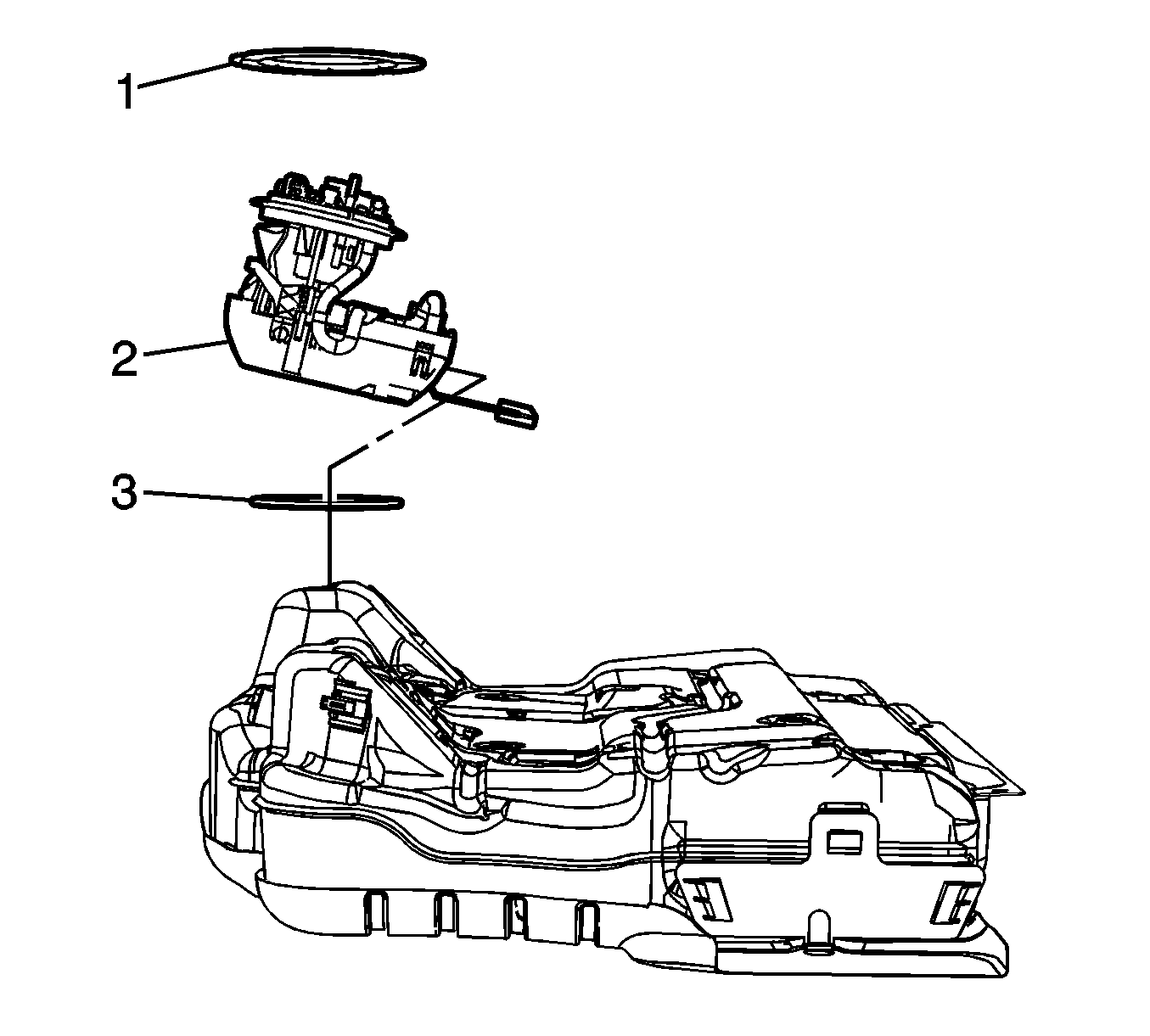
- Remove the fuel sender assembly (2) from the fuel tank.


Notice: Avoid damaging the lock ring. Use only J-45722 to prevent damage to the lock ring.
Notice: Do Not handle the fuel sender assembly by the fuel pipes. The amount of leverage generated by handling the fuel pipes could damage the joints.
Important: Do NOT use impact tools. Significant force will be required to release the lock ring. The use of a hammer and screwdriver is not recommended. Secure the fuel tank in order to prevent fuel tank rotation.

Important:
• The fuel sender assembly may spring up from its position. • When removing the fuel sender assembly from the fuel tank, be aware that the reservoir bucket is full of fuel. It must be tipped slightly during removal to avoid damage to the float. Discard the fuel sender assembly O-ring and replace it with a new
one. • Carefully discard the fuel in the reservoir bucket into an approved container.

Installation Procedure
- Install a NEW O-ring seal (3) onto the fuel sender.
- Install the fuel sender assembly (2) into the fuel tank far enough to connect the vapor line quick connect fitting on the underside of the sender cover.
- Connect the vapor line quick connect fitting (1). Refer to Plastic Collar Quick Connect Fitting Service.
- Align the cover "paddle" or anti-rotation feature with the corresponding feature in the top of the fuel tank.
- Slowly apply pressure to the top of the spring loaded sender cover until the sender aligns flush with the surface of the tank.
- Use the J 45722 in order to install the fuel sender lock ring. Turn the fuel sender lock ring in a clockwise direction.
- Turn the lock ring until the ring seats on the second detent.
- Engage the fuel feed line to the retaining features built into the fuel tank.
- Connect the EVAP vapor line quick connect fittings (1, 2). Refer to Plastic Collar Quick Connect Fitting Service.
- Connect the fuel pressure sensor and sender electrical connections.
- Install the fuel tank. Refer to Fuel Tank Replacement.
- Lower the vehicle.
- Refill the tank.
- Connect the negative battery cable. Refer to Battery Negative Cable Disconnection and Connection.
- Inspect for fuel leaks through the following steps:


Important:
• Some lock rings were manufactured with "DO NOT REUSE" stamped into them. These lock rings may be reused if they are not damaged or warped. • Inspect the lock ring for damage due to improper removal or installation procedures. If damage is found, install a NEW lock ring. • Check the lock ring for flatness.
Important: Always replace the fuel sender seal when installing the fuel sender assembly. Replace the lock ring if necessary. DO NOT apply any type of lubrication in the seal groove.
Ensure the lock ring is installed with the correct side facing upward. A correctly installed lock ring will only turn in a clockwise direction.
| 15.1. | Turn the ignition to the ON position for 2 seconds |
| 15.2. | Turn the ignition to the OFF position for 10 seconds. |
| 15.3. | Turn the ignition to the ON position |
| 15.4. | Check for fuel leaks. |
