For 1990-2009 cars only
Removal Procedure
Important: A NEW adjustable brake pedal cable is required each time it is disconnected from the adjustable brake pedal assembly or adjustable accelerator pedal assembly.
- Remove the knee bolster. Refer to Knee Bolster Replacement .
- Remove the closeout panel. Refer to Instrument Panel Insulator Panel Replacement - Left Side .
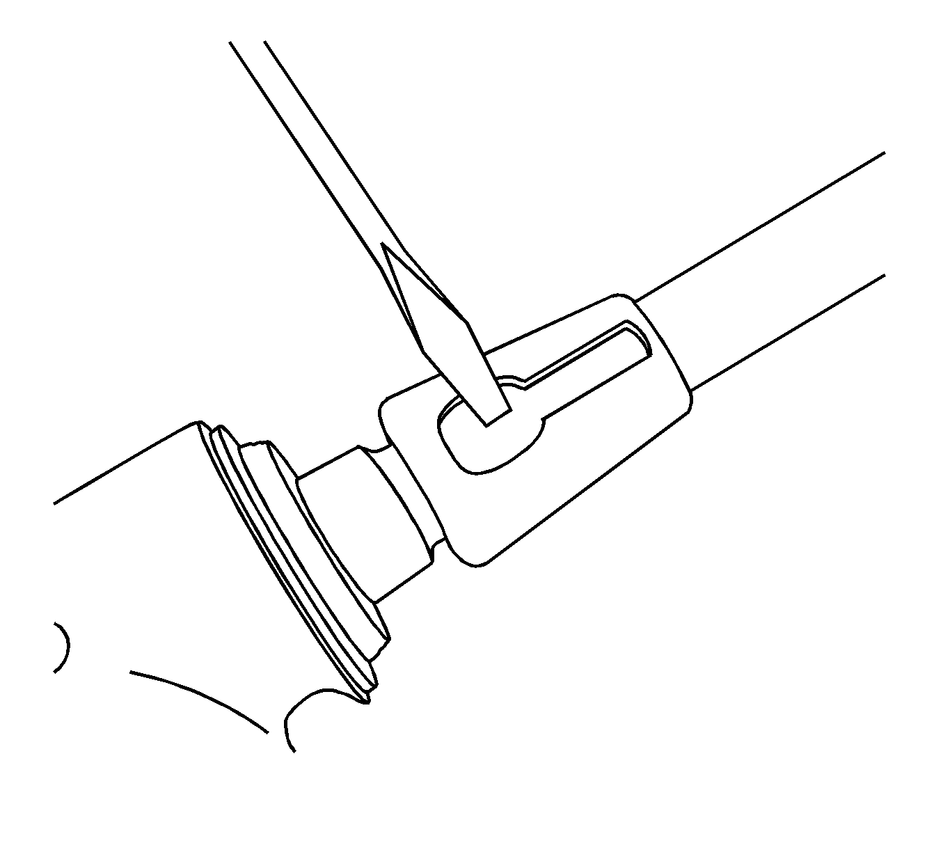
- Use a flat-bladed tool to release the locking tabs from both cable ends.
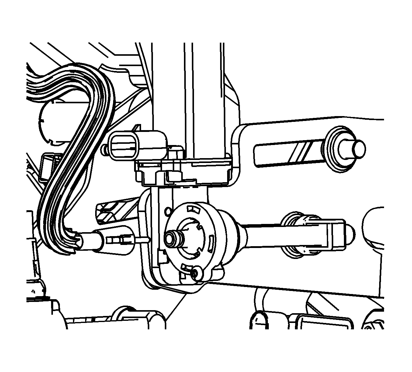
- Remove the cable from the adjustable brake pedal motor assembly.
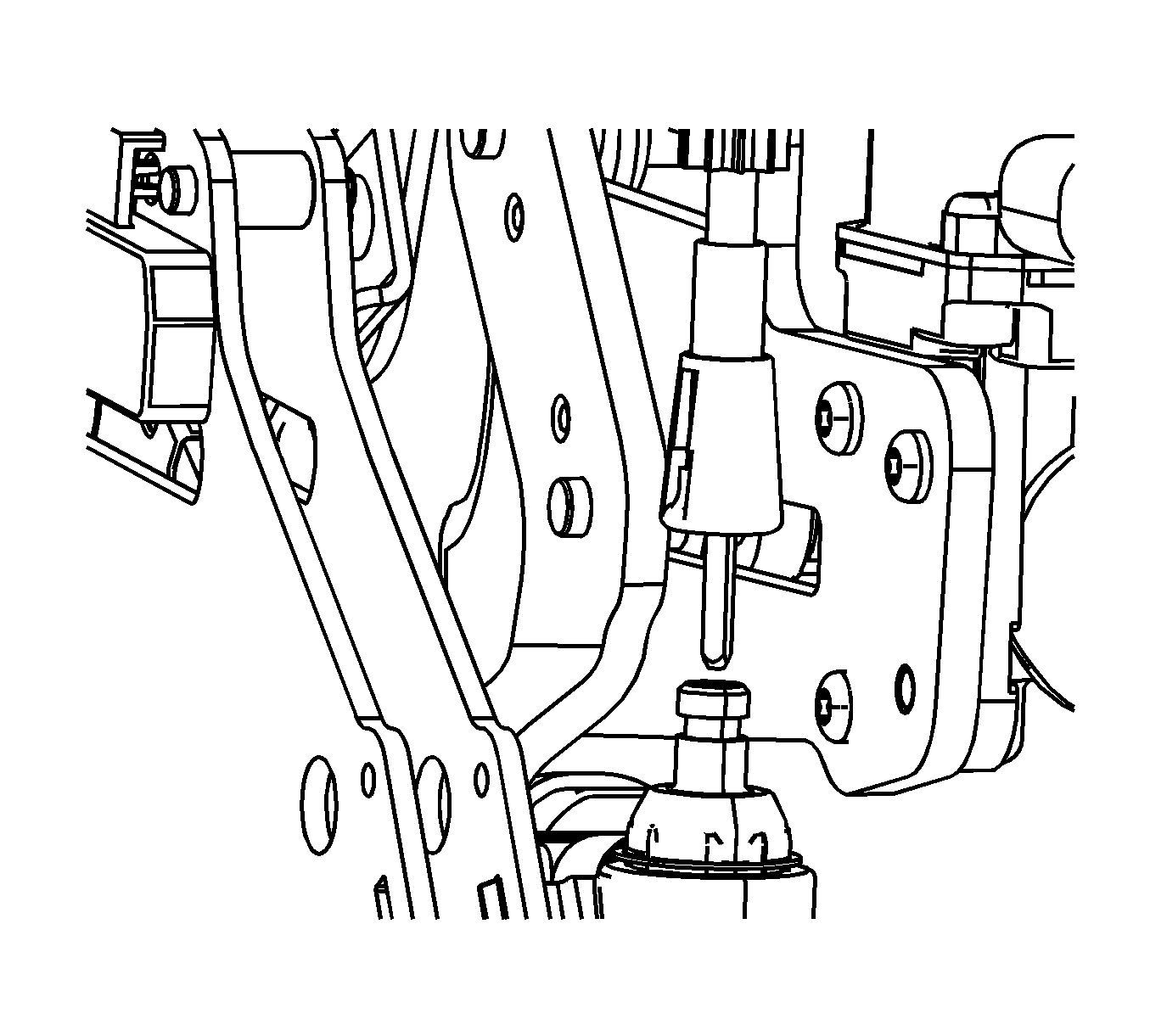
- Remove the cable from the adjustable brake pedal actuator assembly.


Installation Procedure
- Insert a #2 square drive tool into the adjustable brake pedal actuator assembly and turn until the adjustable brake pedal assembly moves fully forward.
- Install the NEW cable to the adjustable brake pedal actuator assembly and ensure the locking tabs of the cable are seated fully.
- Cycle the adjustable pedal position switch until the adjustable accelerator pedal assembly is in a full forward position, toward the dash panel. This may take several attempts to ensure the proper position of the adjustable accelerator pedal assembly to the full forward position.
- Install the NEW cable to the adjustable accelerator motor assembly. Ensure the locking tabs of the cable are seated fully.
- Cycle the adjustable pedal position switch fully rearward and forward ensuring smooth and consistent operation of the adjustable pedals.
- Install the closeout panel. Refer to Instrument Panel Insulator Panel Replacement - Left Side .
- Install the knee bolster. Refer to Knee Bolster Replacement .
- Rehome the brake pedal position sensor. Refer to Brake Pedal Position Sensor Calibration .

Important: Ensure that the adjustable accelerator pedal and adjustable brake pedal are synchronized in the full forward position, toward the dash panel. Failure to perform these next steps will result in improper adjustable pedal operation.

Important: If at any time the adjustable pedal switch is operated for longer than 400 milliseconds and no movement of the brake pedal assembly is detected the system will be disabled and will have to be reset by removing the PEDAL 10-AMP fuse for several seconds and reinstall.
