Transmission Replacement 3.5L (LZ4) W/MN5
Removal Procedure
- Remove the air cleaner outlet duct. Refer to Air Cleaner Outlet Duct Replacement.
- Disconnect the negative battery cable. Refer to Battery Negative Cable Disconnection and Connection.
- Disconnect the transaxle wiring harness from the transaxle and the park neutral position (PNP) switch.
- Remove the shift cable bracket front bolt and shift cable from the lever.
- Remove the transmission wiring harness from the retainer on the transmission.
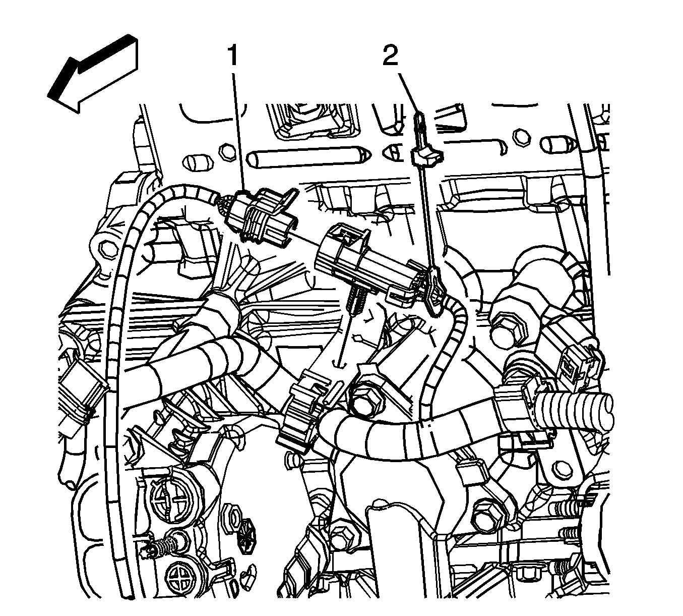
- Disconnect bank 2, O2 sensor 1 electrical connector (4).
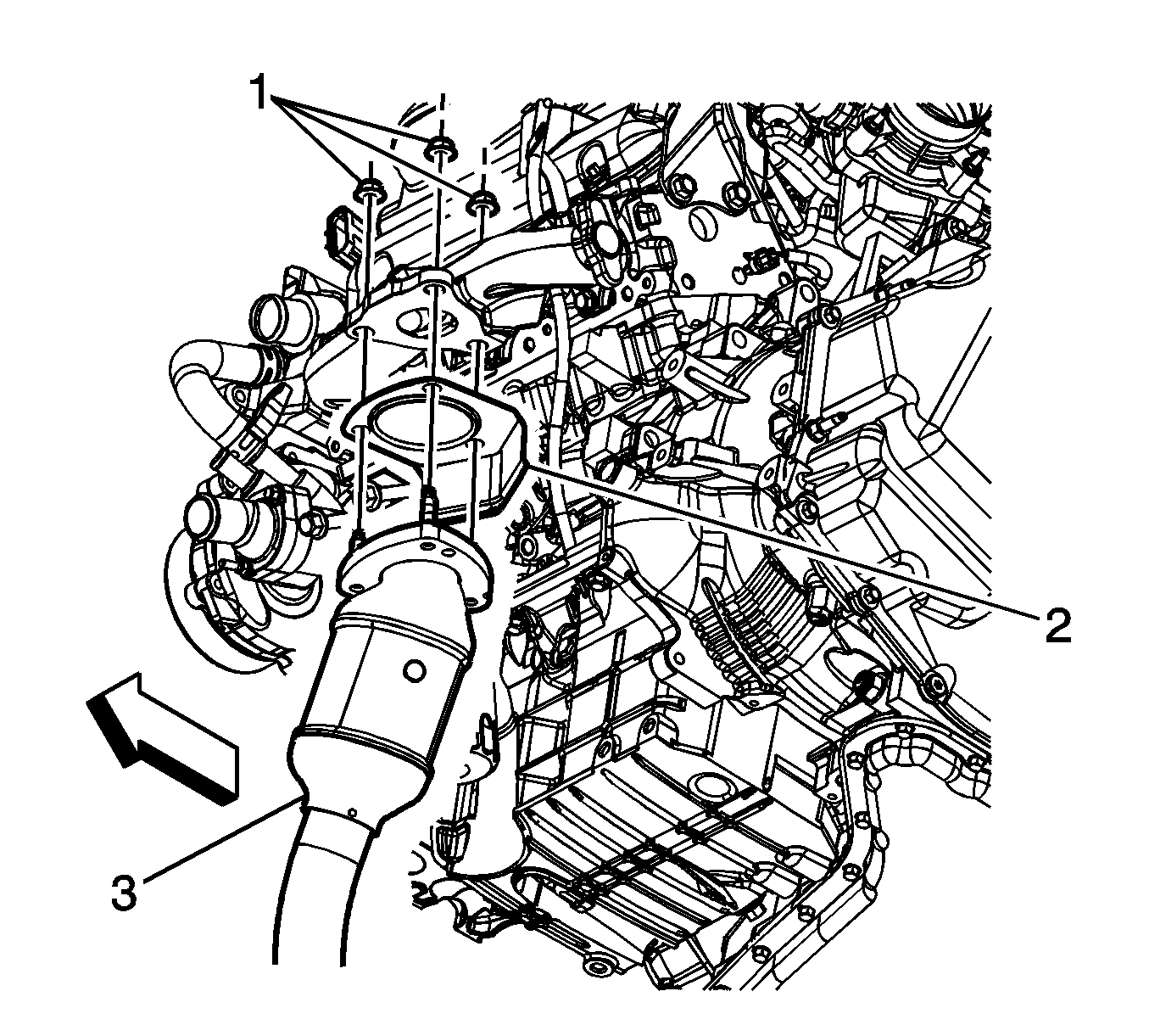
- Remove the left exhaust manifold heat shield.
- Remove the exhaust manifold heat shield.
- Remove the front exhaust pipe nuts (1).
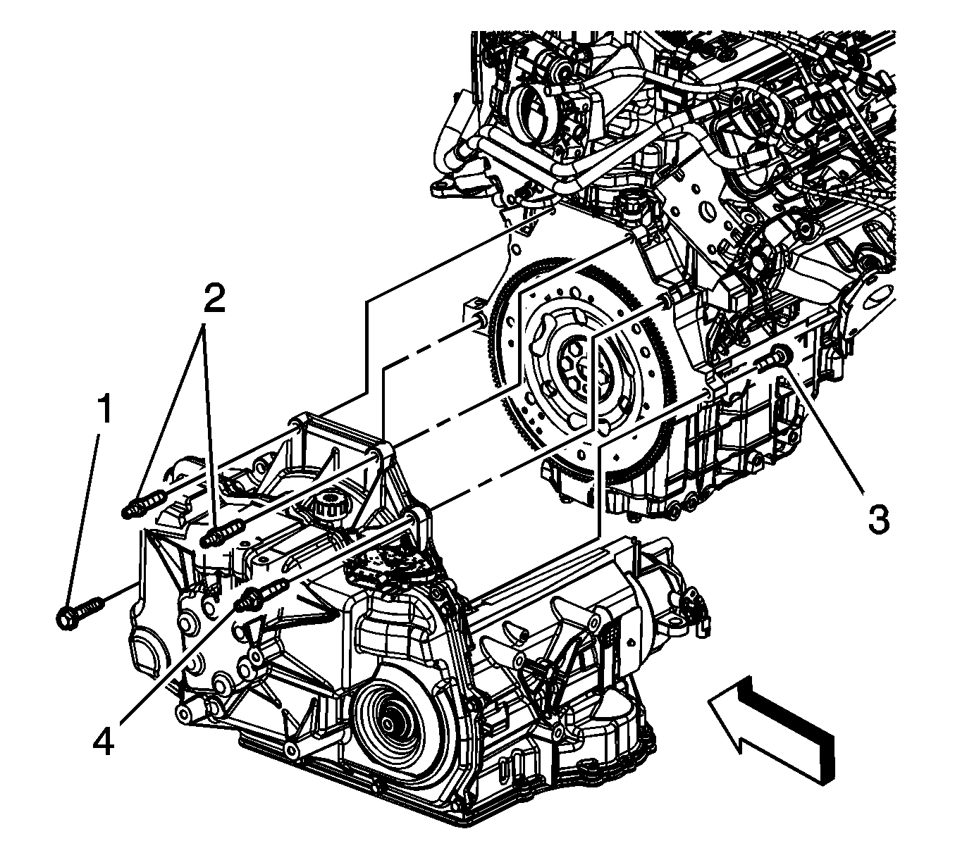
- Remove the upper transmission to engine bolts (2) and stud (4).
- Install the engine support fixture. Refer to Engine Support Fixture.
- Support the radiator and condenser from above using the condenser tabs on each side.
- Raise the vehicle. Refer to Lifting and Jacking the Vehicle.
- Remove the front wheels and tires. Refer to Tire and Wheel Removal and Installation.
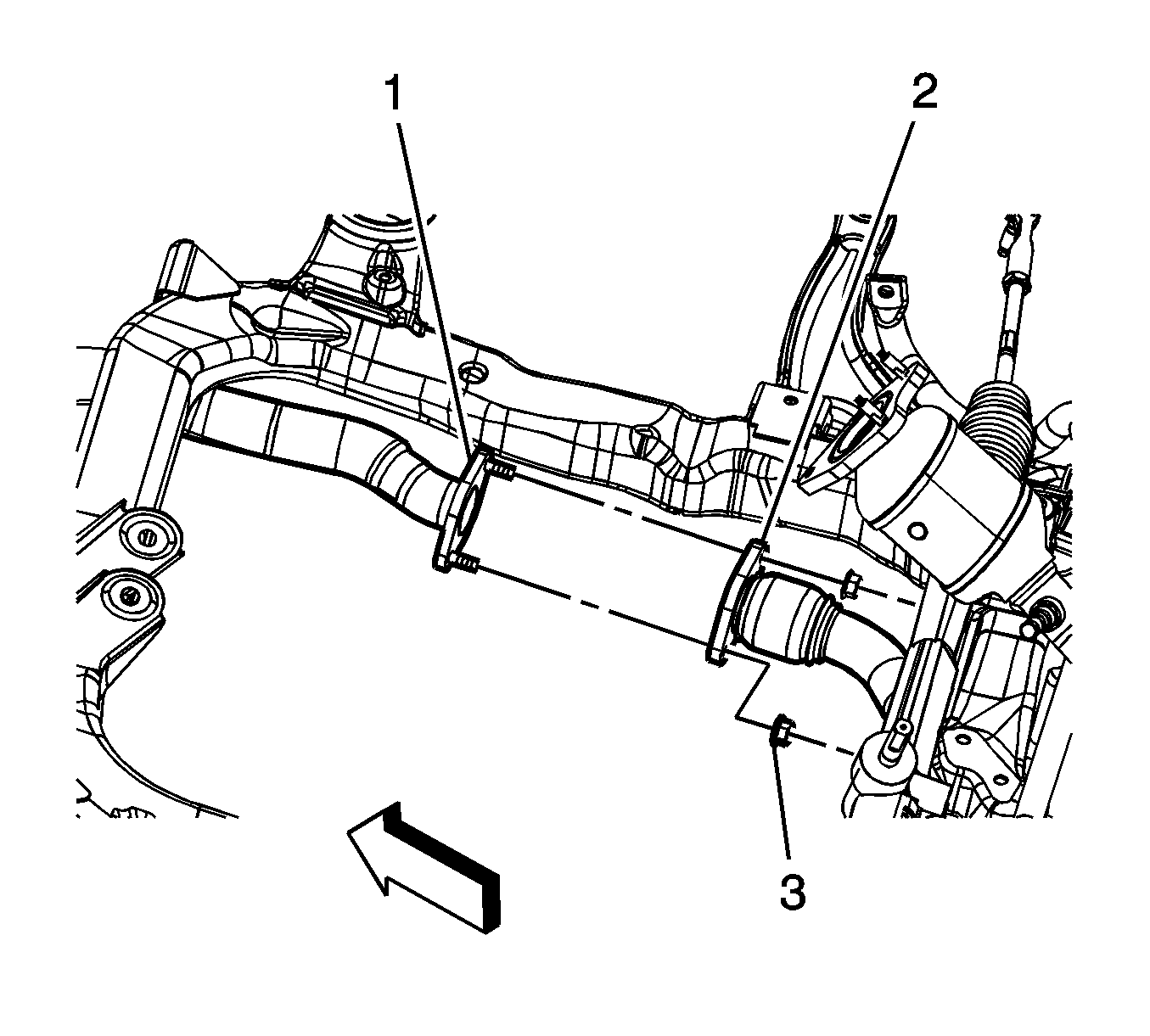
- Disconnect the bank 2, O2 sensor 2 electrical connector (2).
- Remove the left catalytic converter to right catalytic converter nuts (3).
- Remove the left catalytic converter (1).
- Remove the steering gear intermediate shaft.
- Remove the frame. Refer to Frame Replacement.
- Disconnect the wheel drive shafts from the transaxle. Refer to Wheel Drive Shaft Replacement.
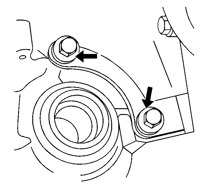
- Remove the 3 bolts from the transmission brace near the right axle shaft.
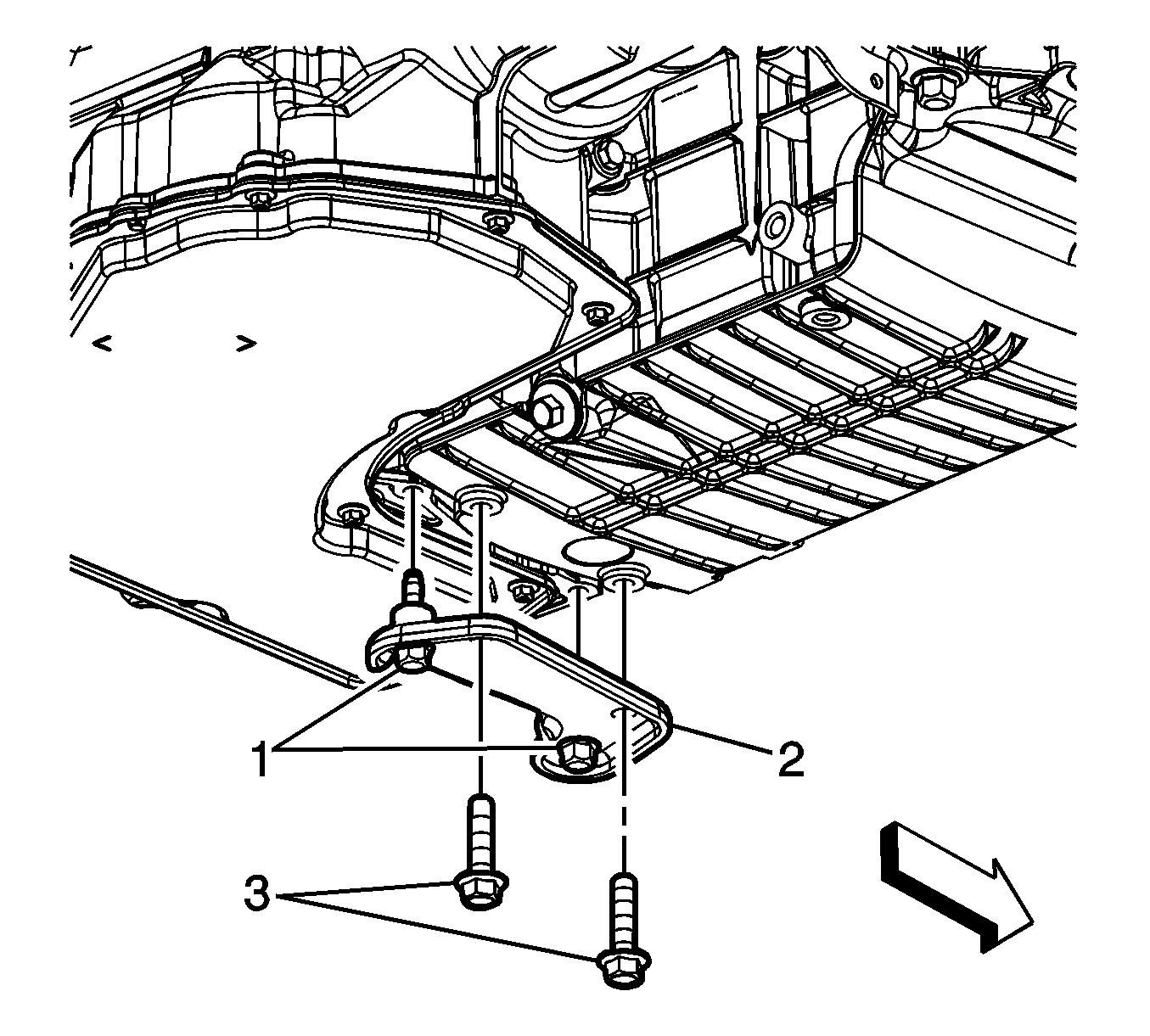
- Remove the oil pan to bellhousing bolts (1, 3) and bracket (2).
- Remove the flywheel inspection cover.
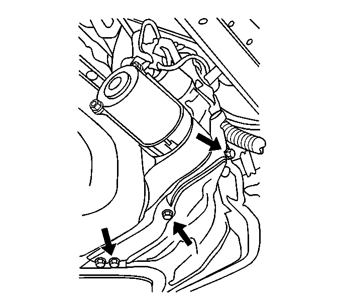
- Remove the starter. Refer to Starter Motor Replacement.
- Mark the relationship of the flywheel to the torque converter for reassembly.
- Remove the torque converter to flywheel bolts.
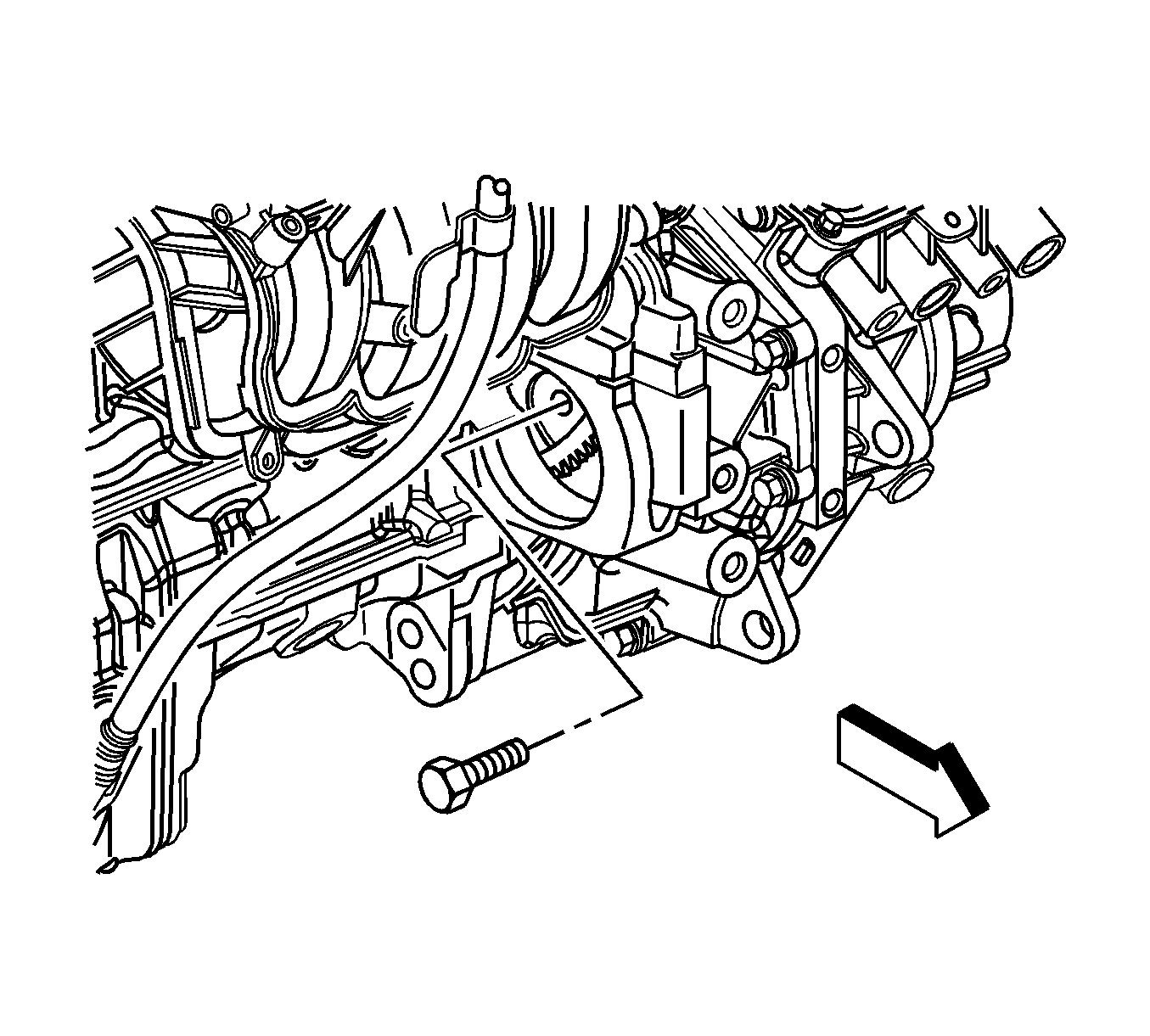
- Remove the transmission oil cooler lines by removing the nut holding the bracket to the transaxle case.
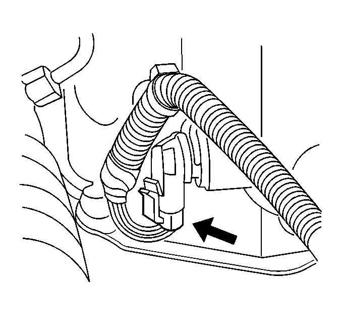
- Disconnect the vehicle speed sensor (VSS) wiring harness from the sensor.
- Disconnect the rear heated oxygen sensor (HO2S) harness from the rear transmission mount.
- Remove the remaining (rear) bolt from the shift cable bracket.
- Remove the front transmission mount bracket from the transmission.
- Use a transmission jack in order to support the transmission.
- Remove the remaining bellhousing bolts (1, 3) and separate the transmission from the engine.
- Lower the transmission with the transmission jack far enough to remove the transmission.
- If the transmission is being replace or installed in a holding fixture, remove the rear transmission mount bracket from the transmission.
- If the transmission is being replaced, remove the PNP switch from the transmission.
- If the transmission is being replaced, remove the transmission mount.
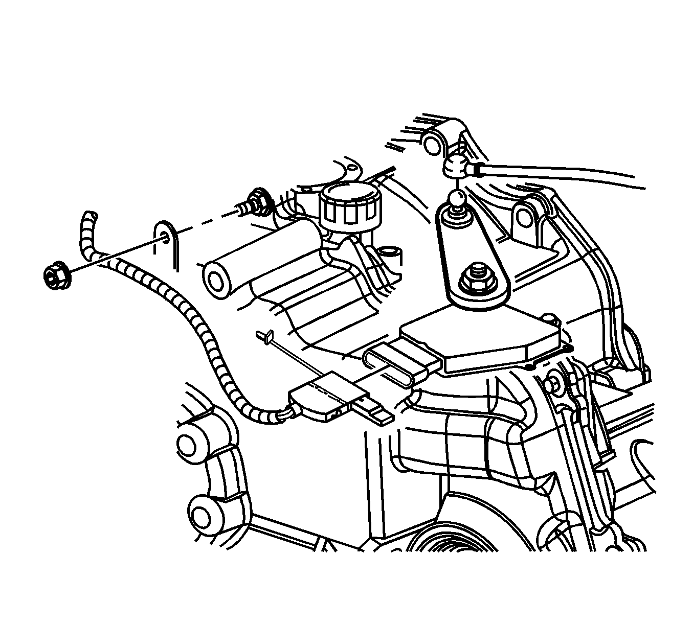
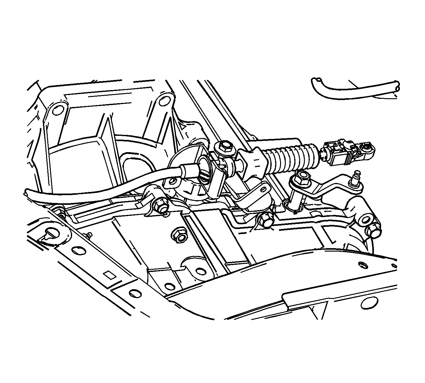
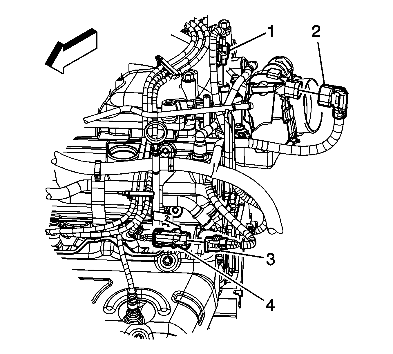
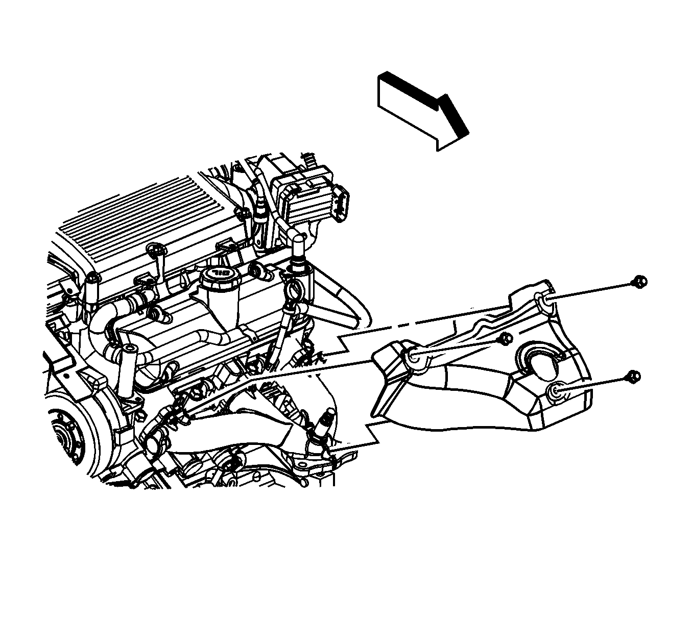
(Powertrain shown removed for clarity).
Important: It is only necessary to remove the control arms from the frame if the frame is being replaced.

Installation Procedure
- If transmission is being replaced, install the following to the transmission:
- Install the side cover transmission mount bracket to the transmission.
- Install the rear transmission mount bracket to the transmission.
- Position the transaxle in the vehicle.
- Install the lower transmission to engine bolts (1, 3).
- Install the front transmission mount bracket to the transmission.
- Install the wheel drive shafts to the transaxle. Refer to Wheel Drive Shaft Replacement.
- Connect the wiring harness to the VSS.
- Install the torque converter to flywheel bolts.
- Install the starter. Refer to Starter Motor Replacement.
- Install the flywheel inspection cover bolts.
- Connect the transaxle oil cooler pipes to the transaxle.
- Install the oil pan to bellhousing bracket (2) and bolts (1, 3).
- Install the 3 bolts to the transmission brace at the final drive area and tighten.
- Remove the transmission jack.
- Install the frame. Refer to Frame Replacement.
- Install the engine splash shields.
- Install the front wheels and tires. Refer to Tire and Wheel Removal and Installation.
- Lower the vehicle.
- Remove the radiator and condenser support and the engine support fixture.
- Install the upper transmission to engine bolts (2) and stud (4).
- Install the shift cable bracket and shift cable to the lever.
- Install the left catalytic converter (3). Refer to Catalytic Converter Replacement - Left Side.
- Connect bank 2, O2 sensor 2 electrical connector (1).
- Install the left exhaust manifold heat shield.
- Install the heat shield bolts.
- Connect bank 2, O2 sensor 1 electrical connector (4).
- Connect the electrical connectors to the PNP switch and transaxle.
- Connect the negative battery cable. Refer to Battery Negative Cable Disconnection and Connection.
- Install the air cleaner outlet duct. Refer to Air Cleaner Outlet Duct Replacement.
- Add automatic transmission fluid (ATF) and verify the proper fluid level of the transaxle.
- Reset the TAP values. Refer to Transmission Adaptive Functions.
- Road test the vehicle.
| • | The PNP switch |
| • | The torque converter clutch (TCC) lock up clutch O-ring. |
| • | Transfer the transaxle from the bench fixture to the transmission jack. |
Notice: Refer to Fastener Notice in the Preface section.

Tighten
Tighten the bolts to 90 N·m (66 lb ft).

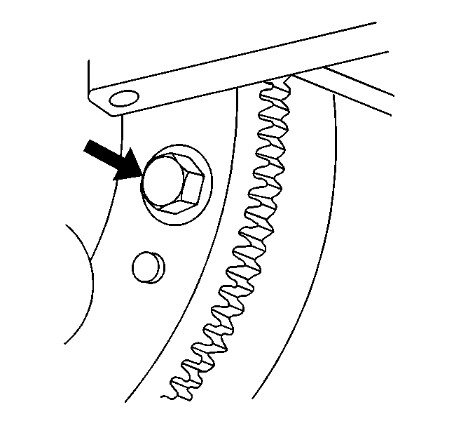
Tighten
Tighten the bolts to 62 N·m (46 lb ft).

Tighten
Tighten the bolts to 10 N·m (89 lb in).
Tighten
Tighten the pipes to 8 N·m (71 lb in).

Tighten
Tighten the bolts to 72 N·m (53 lb ft).

Tighten
Tighten the bolts/stud to 90 N·m (66 lb ft).


Tighten
Tighten the bolts to 10 N·m (89 lb in).


Important: It is recommended that transmission adaptive pressure (TAP) information be reset.
Resetting the TAP values using a scan tool will erase all learned values in all cells. As a result, the ECM, PCM or TCM will need to relearn TAP values. Transmission performance may be affected as new TAP values are learned.Transmission Replacement 2.4L (LE5) W/MN5
Special Tools
| • | J 35944-A Transmission Oil Cooler Flusher |
| • | J 43653 Flywheel Holding Tool |
Removal Procedure
- Remove the battery tray. Refer to Battery Tray Replacement.
- Disconnect the air cleaner outlet duct. Refer to Air Cleaner Outlet Duct Replacement.
- Disconnect the transaxle wiring harness from the transaxle and the park neutral position (PNP) switch.
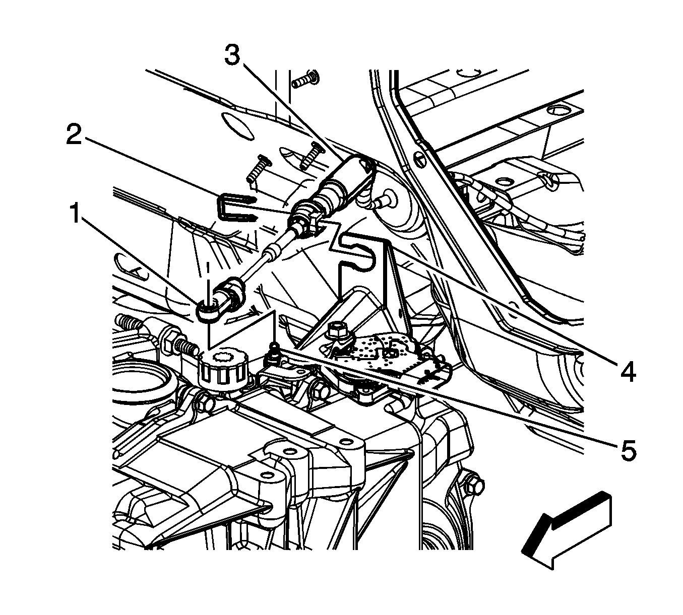
- Disconnect the transaxle shift control cable terminal (1) from the transaxle manual shift lever pin (5).
- Remove the retainer (2) from the transaxle shift control cable.
- Press the locking tabs inward in order to release the transaxle shift control cable (3) from the cable bracket (4).
- Remove the shift cable bracket.
- Remove the transaxle wiring harness from the retainer on the transaxle.
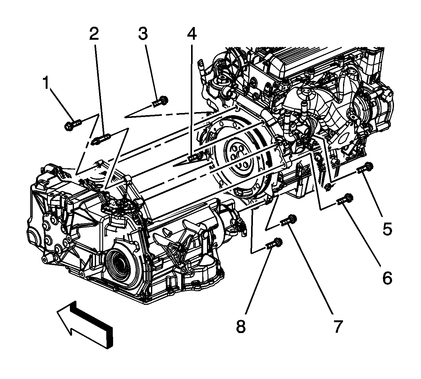
- Remove the upper transaxle to engine studs (1, 2) and bolts (5, 6).
- Install the engine support fixture. Refer to Engine Support Fixture.
- Remove the left transmission mount. Refer to Transmission Mount Replacement - Left Side.
- Secure the radiator and condenser to the vehicle structure and the engine in order to prepare for frame removal.
- Raise the vehicle. Refer to Lifting and Jacking the Vehicle.
- Remove the front wheels and tires. Refer to Tire and Wheel Removal and Installation.
- Remove the engine splash shields. Refer to Engine Splash Shield Replacement - Left Side and Engine Splash Shield Replacement - Right Side.
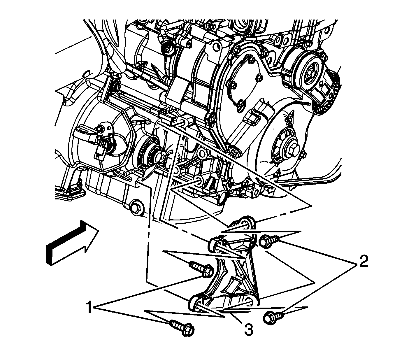
- Remove the bolts (1, 2) from the transaxle brace.
- Remove the transaxle brace (3).
- Remove the starter. Refer to Starter Motor Replacement.
- Mark the relationship of the flywheel to the torque converter for reassembly.
- Use the J 43653 to prevent the crankshaft from rotating.
- Remove the torque converter to flywheel bolts.
- Remove the nut holding the transaxle cooler line retainer to the transaxle.
- Disconnect the transaxle cooler lines from the transaxle.
- Disconnect the vehicle speed sensor (VSS) wiring harness from the sensor.
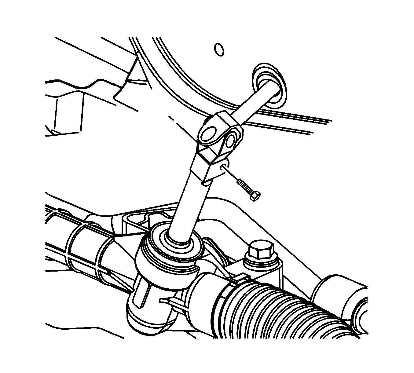
- Remove the intermediate shaft to steering gear pinch bolt. Discard the bolt.
- Disconnect the intermediate shaft from the steering gear.
- Disconnect the tie rods from the steering knuckle. Refer to Steering Linkage Outer Tie Rod Replacement.
- Disconnect the stabilizer shaft links from the stabilizer shaft. Refer to Stabilizer Shaft Link Replacement.
- Disconnect the ball joints from the steering knuckles. Refer to Lower Control Arm Replacement.
- Remove the frame. Refer to Frame Replacement.
- Disconnect the wheel drive shafts from the transaxle. Refer to Wheel Drive Shaft Replacement. Secure the wheel drive shafts out of the way.
- Support the transaxle with a suitable jack.
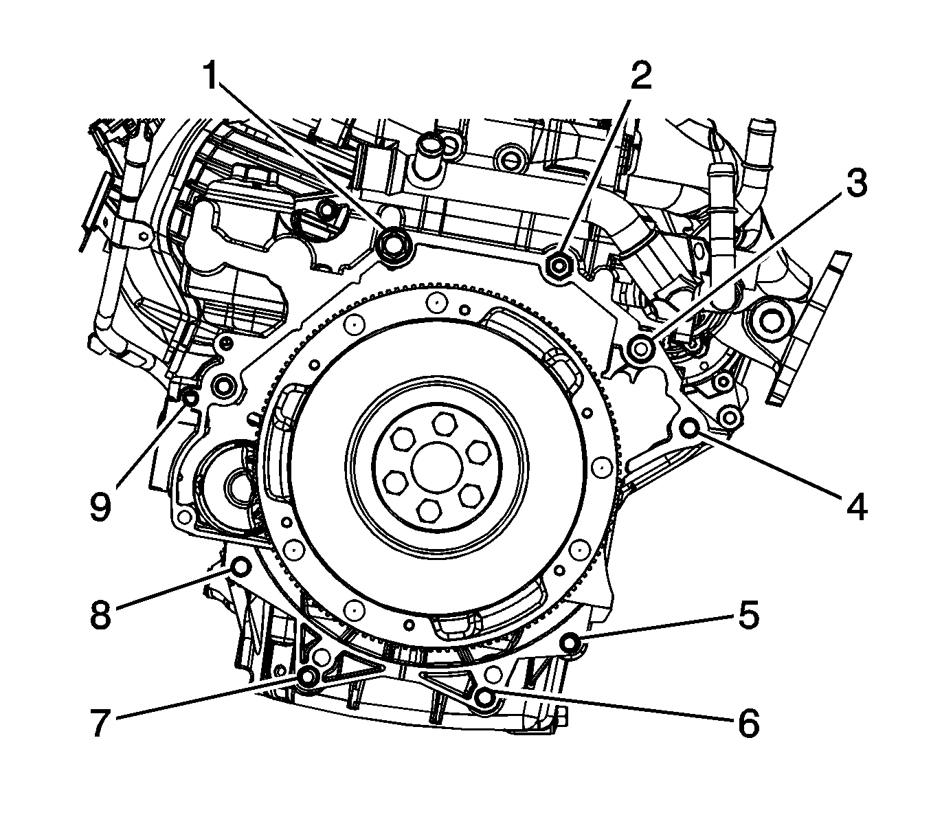
- Remove the lower transaxle to engine bolts (5, 6, 7, 8, 9).
- Separate the engine and the transaxle.
- Remove the transaxle from the vehicle.
- If the transaxle is being replaced, remove the PNP switch from the transaxle. Refer to Park/Neutral Position Switch Replacement.
- Flush the transaxle cooler and the lines with J 35944-A .


Installation Procedure
- If previously removed, Install the PNP switch. Refer to Park/Neutral Position Switch Replacement.
- Position the transaxle in the vehicle.
- Install the lower transaxle to engine bolts (5, 6, 7, 8, 9).
- Install the wheel drive shafts to the transaxle. Refer to Wheel Drive Shaft Replacement.
- Lubricate the transaxle cooler pipes before inserting into seals.
- Connect the transaxle cooler pipes to the transaxle.
- Install the transaxle cooler pipes retainer nut.
- Use the J 43653 to prevent the crankshaft from rotating.
- Install the torque converter to flywheel bolts.
- Install the starter. Refer to Starter Motor Replacement.
- Install the frame. Refer to Frame Replacement.
- Connect the intermediate shaft to the steering gear shaft.
- Install the new steering gear pinch bolt to the intermediate shaft.
- Connect the ball joints to the steering knuckles. Refer to Lower Control Arm Replacement.
- Connect the stabilizer shaft links to the stabilizer shaft. Refer to Stabilizer Shaft Link Replacement.
- Connect the tie rods to the steering knuckle. Refer to Steering Linkage Outer Tie Rod Replacement.
- Connect the wiring harness to the VSS.
- Install the transaxle brace (3).
- Install the transaxle brace bolts (1, 2).
- Install the engine splash shields. Refer to Engine Splash Shield Replacement - Left Side and Engine Splash Shield Replacement - Right Side.
- Install the front wheel and tire assemblies. Refer to Tire and Wheel Removal and Installation.
- Lower the vehicle.
- Install the left transaxle mount. Refer to Transmission Mount Replacement - Left Side.
- Install the upper transaxle to engine bolts (5, 6) and studs (1, 2).
- Untie the radiator, air conditioning condenser, and fan module assembly.
- Remove the engine support fixture. Refer to Engine Support Fixture.
- Connect the transaxle wiring harness to the main transaxle electrical connector, and the PNP switch.
- Install the shift cable bracket.
- Install the transaxle shift control cable (3) to the cable bracket (4).
- Install the retainer (2) to the transaxle shift control cable.
- Connect the transaxle shift control cable terminal (1) to the transaxle manual shift lever pin (5).
- Install the battery tray. Refer to Battery Tray Replacement.
- Connect the air cleaner outlet duct. Refer to Air Cleaner Outlet Duct Replacement.
- Add automatic transmission fluid (ATF) and verify the proper fluid level of the transaxle.
- Reset the TAP values. Refer to Transmission Adaptive Functions.
- Road test the vehicle.
Notice: Refer to Fastener Notice in the Preface section.

Tighten
Tighten the bolts to 75 N·m (55 lb ft).
Tighten
Tighten the nut to 7 N·m (62 lb in).

Tighten
Tighten the torque converter bolts to 60 N·m (44 lb ft).

Tighten
Tighten the steering gear pinch bolt to 49 N·m (36 lb ft).


Tighten
Tighten the bolts to 53 N·m (39 lb ft).

Tighten
Tighten the bolts (5, 6) and studs (1, 2) to 75 N·m (55 lb ft).


Important: It is recommended that transmission adaptive pressure (TAP) information be reset.
Resetting the TAP values using a scan tool will erase all learned values in all cells. As a result, the ECM, PCM, or TCM will need to relearn TAP values. Transmission performance may be affected as new TAP values are learned.