For 1990-2009 cars only
Special Tools
J 23498-A Driveshaft Inclinometer
Note: If for some reason there is pressure or preload against the powertrain, it can be put out of design position and this will put stress on the flex coupling in the exhaust system when the vehicle is driven and the out of position powertrain may cause the exhaust downpipe to hit the heat shield in the exhaust tunnel during torque loads.
Note: When lifting the vehicle to perform this procedure, the vehicle MUST be lifted using a frame contact hoist, in order for the wheels and suspension to hang free.
- Raise and support the vehicle. Refer to Lifting and Jacking the Vehicle.
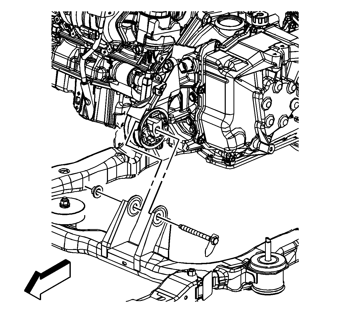
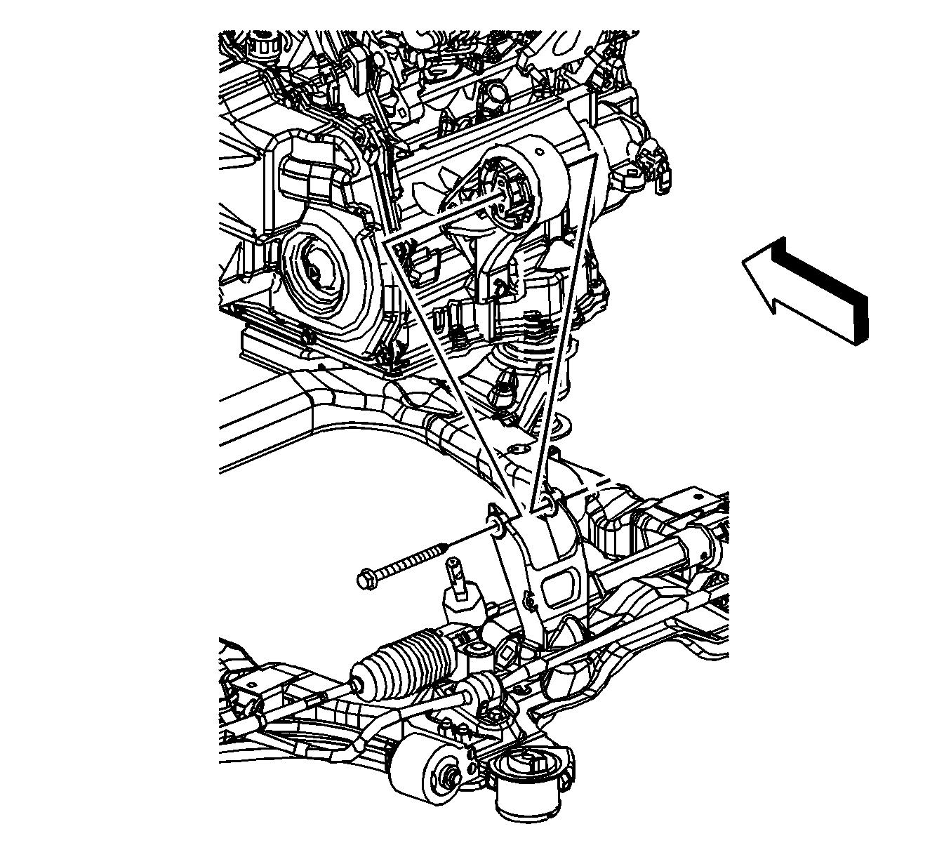
- Loosen, but DO NOT REMOVE the front transaxle mount through bolt.
- Loosen, but DO NOT REMOVE the rear transaxle mount through bolt.
- Install the J 23498-A on the bottom of the flex coupling of the exhaust pipe.
- Rock the engine by hand until the J 23498-A reading is as close to "0" degrees as possible.
- While still holding the powertrain in position, tighten the front through bolt.
- Tighten the rear through bolt.
- After the through bolts have been tightened, re-check the angle.
- There should be no more then "5" degrees of angle in the flex coupling with the powertrain in the static position.
- If there is no more then "5" degrees of angle, tighten the through bolts to specifications.
- If there is more then "5" degrees of angle, loosen the through bolts and return to step 5.


Caution: Refer to Fastener Caution in the Preface section.
Tighten
Tighten the bolts to 90 N·m (66 lb ft).
