For 1990-2009 cars only
Warning: Refer to Brake Fluid Irritant Warning in the Preface section.
Caution: Refer to Brake Fluid Effects on Paint and Electrical Components Caution in the Preface section.
Removal Procedure
- Disconnect the brake fluid level indicator switch electrical connector.
- Remove and discard the brake fluid from the master cylinder reservoir.
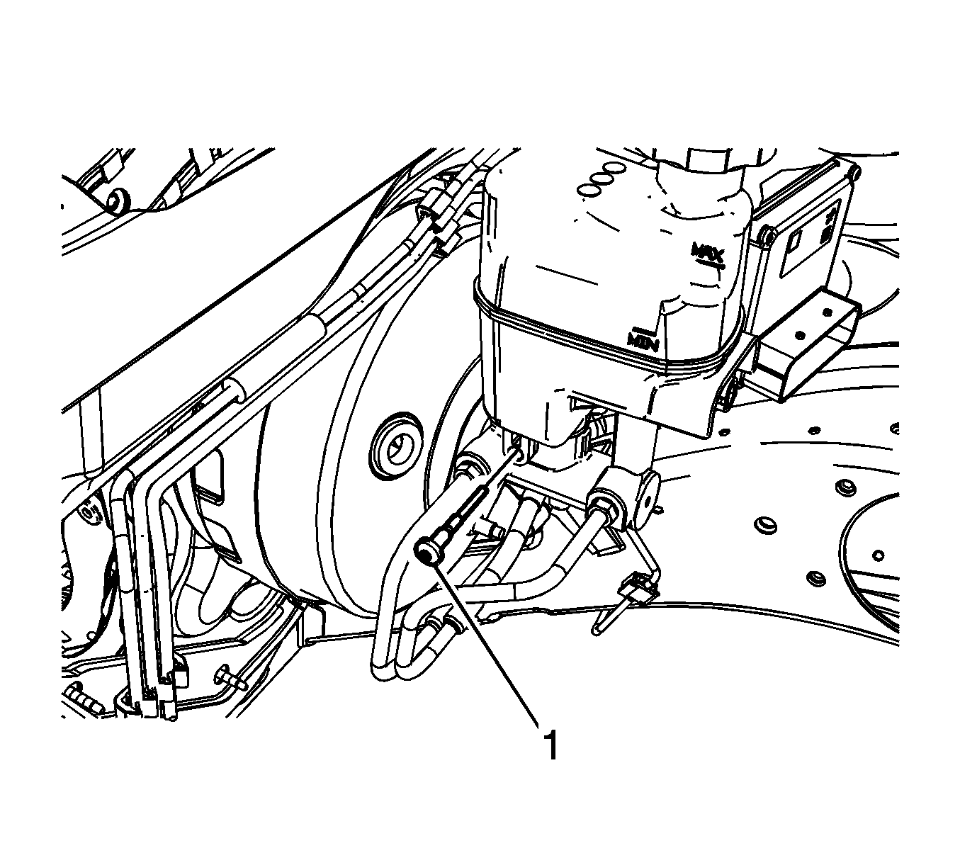
- Remove the master cylinder reservoir bolt (1).
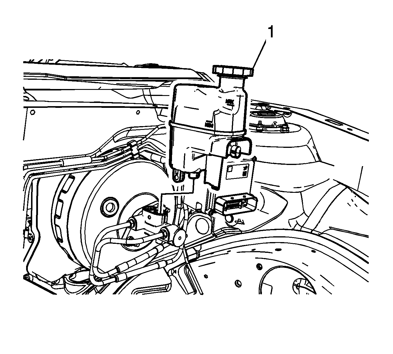
- Remove the reservoir (1) from the master cylinder.
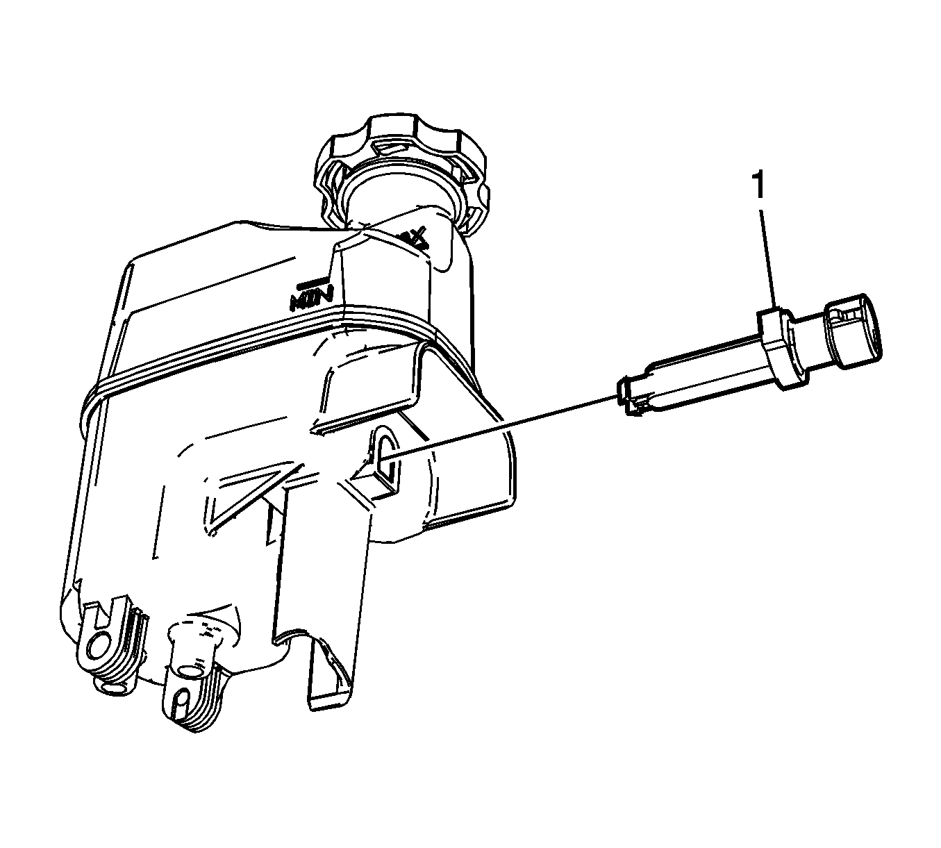
- Remove the fluid level indicator switch (1) from the master cylinder.


Compress the locking tabs on the switch from the underside of the master cylinder reservoir.
Installation Procedure
- Clean the reservoir with denatured alcohol.
- Dry the reservoir with filtered, non-lubricated compressed air.
- Install the fluid level indicator switch (1) to the master cylinder.
- Install the reservoir (1) to the master cylinder.
- Install the master cylinder reservoir bolt (1).
- Connect the brake fluid level indicator switch electrical connector.
- Fill the master cylinder reservoir. Refer to Master Cylinder Reservoir Filling.

Ensure the locking tabs on the switch are fully engaged to the master cylinder reservoir.

Caution: Refer to Fastener Caution in the Preface section.

Tighten
Tighten the bolt to 8 N·m (71 lb in).
