For 1990-2009 cars only
Removal Procedure
- Raise and support the vehicle. Refer to Lifting and Jacking the Vehicle.
- Remove the tire and wheel. Refer to Tire and Wheel Removal and Installation.
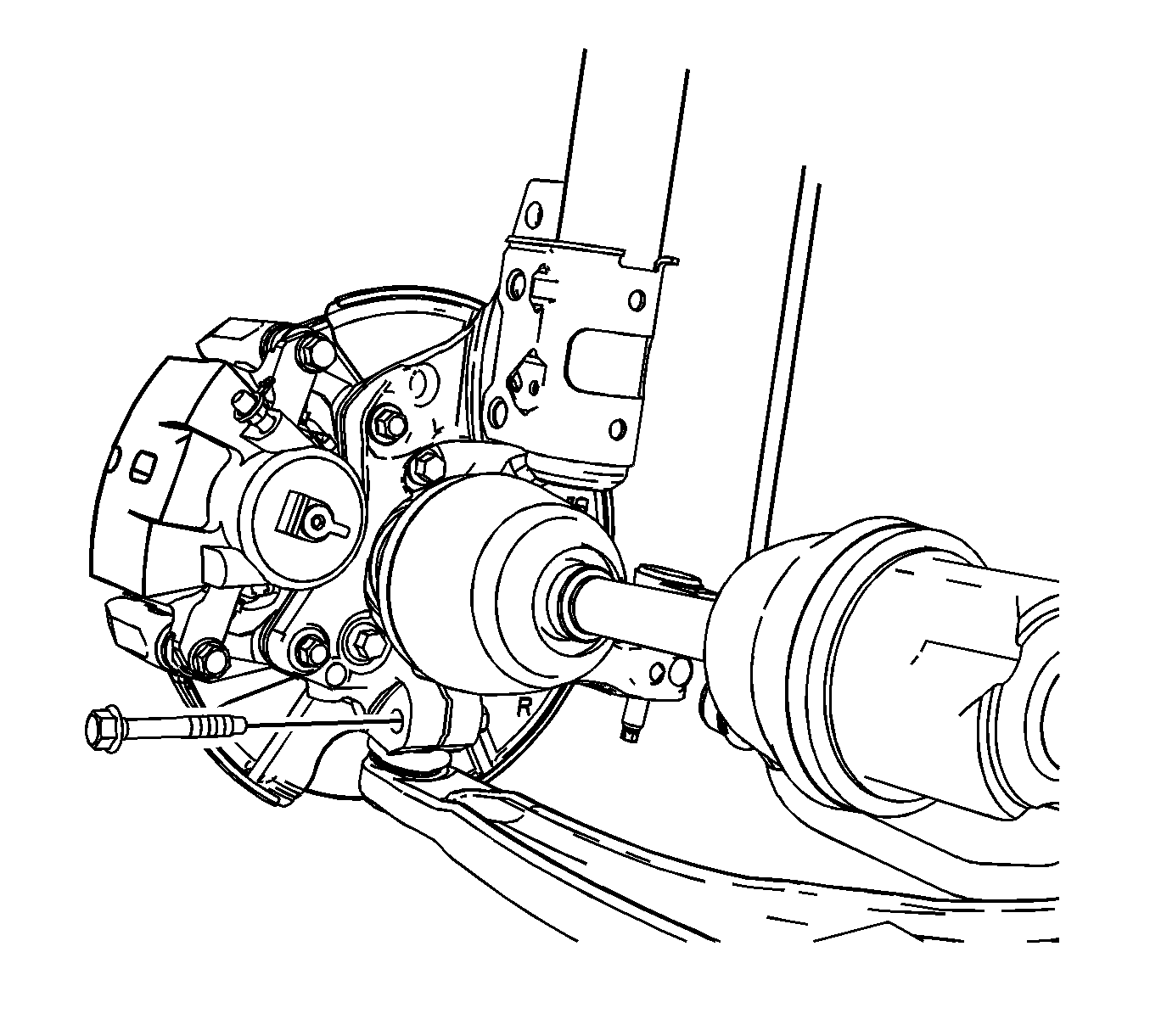
- Remove the lower ball joint to knuckle nut and bolt.
- Separate the lower control arm from the knuckle.
- If removing the left lower control arm, refer to the following:
- If removing the right lower control arm, refer to the following:
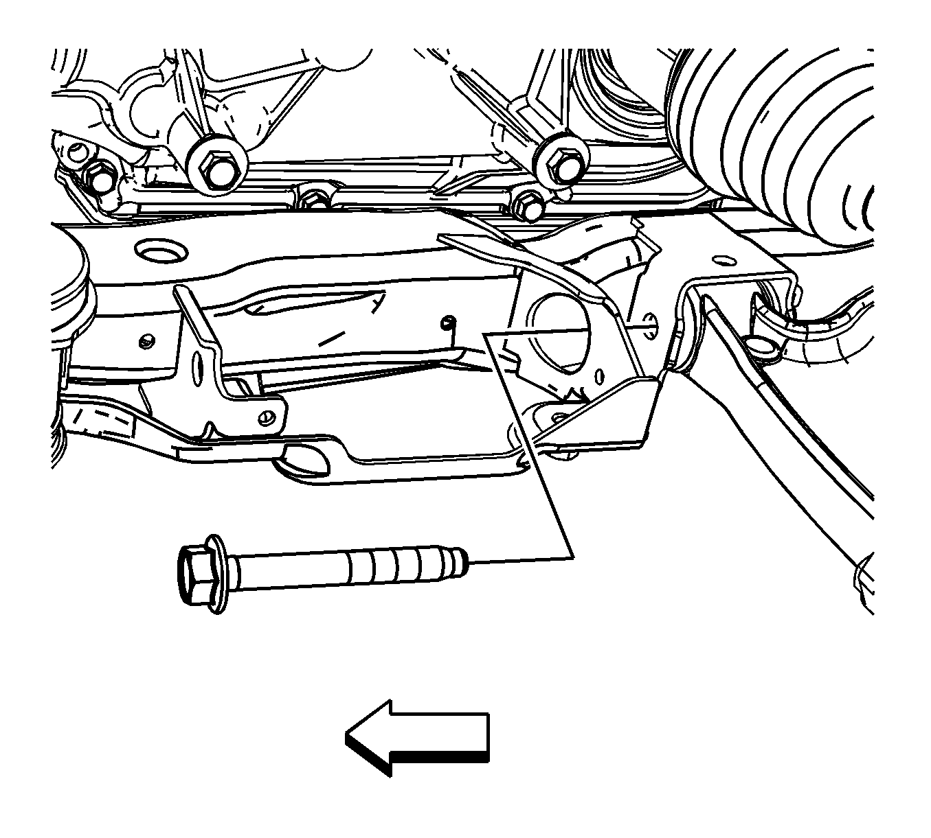
- Remove the front lower control arm bolt.
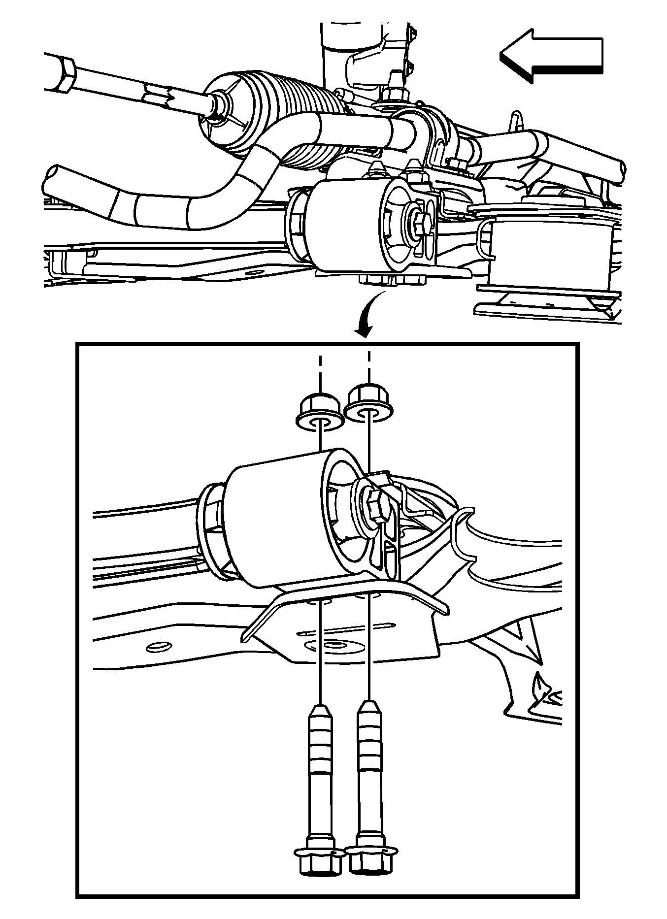
- Remove the rear lower control arm bushing nuts and bolts. Refer to Front Lower Control Arm Bushing Replacement.
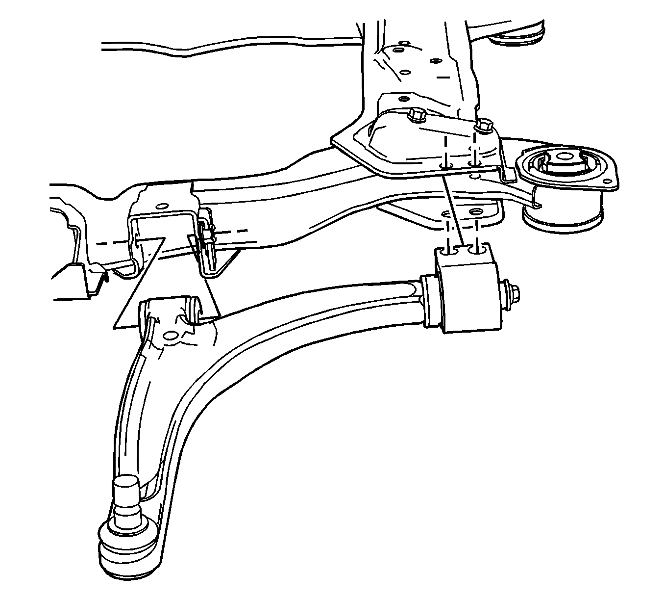
- Remove the lower control arm from the cradle.

Note: DO NOT re-use the lower ball joint bolt. Discard and use NEW only.
| • | For vehicles equipped with the 4T45-E transmission, remove the left side transmission mount. Refer to Transmission Mount Replacement - Left Side. |
| • | For vehicles equipped with the 4T65-E transmission, remove the left side transmission mount. Refer to Transmission Mount Replacement - Left Side. |
| • | For vehicles equipped with the 6T70/6T75 transmission, remove the left side transmission mount. Refer to Transmission Mount Replacement - Left Side. |
| • | For vehicles equipped with the 3.5L engine, remove the right engine mount. Refer to Engine Mount Replacement. |
| • | For vehicles equipped with the 3.6L engine, remove the right engine mount. Refer to Engine Mount Replacement - Right Side. |
| • | For vehicles equipped with the 3.9L engine, remove the right engine mount. Refer to Engine Mount Replacement. |


Installation Procedure
- Position the lower control arm in the cradle.
- Install and hand tighten the rear lower control arm bushing nuts and bolts.
- Install and hand tighten the front lower control arm bolt.
- Install the ball joint to knuckle bolt and nut.
- Load the front suspension with the proper jack stand before tightening the bolts to specifications.
- Tighten the front lower control arm bolt.
- Tighten the rear bushing to frame bolts.
- Remove the jack stand.
- If installing the left lower control arm, refer to the following:
- If installing the right lower control arm, refer to the following:
- Install the tire and wheel. Refer to Tire and Wheel Removal and Installation.
- Verify wheel alignment. Refer to Wheel Alignment Specifications.
- Remove the support and lower the vehicle.


Caution: Refer to Fastener Caution in the Preface section.

Tighten
Tighten the ball joint bolt and nut to 50 N·m (37 lb ft). Reverse the nut 3/4 of a turn. Tighten to 50 N·m (37 lb ft) plus 30 degrees.
Tighten
Tighten the lower control arm bolt to 50 N·m (37 lb ft) plus 90 degrees.
Tighten
Tighten the lower control arm bolt to 50 N·m (37 lb ft) plus 90 degrees.
| • | For vehicles equipped with the 4T45-E transmission, remove the left side transmission mount. Refer to Transmission Mount Replacement - Left Side. |
| • | For vehicles equipped with the 4T65-E transmission, remove the left side transmission mount. Refer to Transmission Mount Replacement - Left Side. |
| • | For vehicles equipped with the 6T70/6T75 transmission, remove the left side transmission mount. Refer to Transmission Mount Replacement - Left Side. |
| • | For vehicles equipped with the 3.5L engine, remove the right engine mount. Refer to Engine Mount Replacement. |
| • | For vehicles equipped with the 3.6L engine, remove the right engine mount. Refer to Engine Mount Replacement - Right Side. |
| • | For vehicles equipped with the 3.9L engine, remove the right engine mount. Refer to Engine Mount Replacement. |
