1-2 Shift Solenoid (SS) Valve
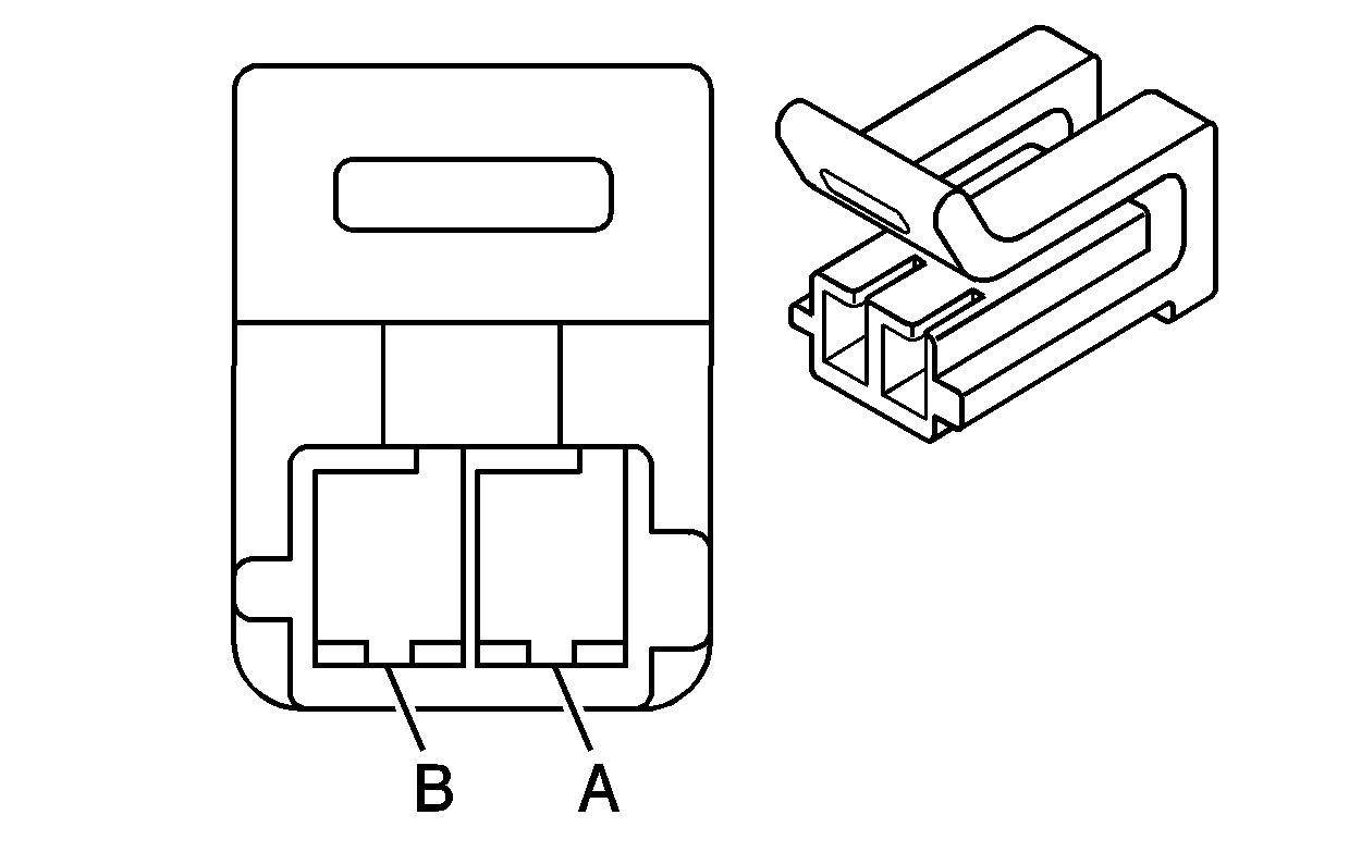
Connector Part Information
|
Terminal Part Information
|
Pin | Wire Color | Circuit No. | Function |
|---|---|---|---|
A | 0.5 BK | 1222 | Shift Solenoid A Valve Control |
B | 0.5 WH | 1525 | Clutch Pressure Control Solenoid Valve 1 High Control |
3-4 Shift Solenoid (SS) Valve

Connector Part Information
|
Terminal Part Information
|
Pin | Wire Color | Circuit No. | Function |
|---|---|---|---|
A | 0.5 GY | 898 | Shift Solenoid C Valve Control |
B | 0.5 WH | 1525 | Clutch Pressure Control Solenoid Valve 1 High Control |
4-5 Shift Solenoid (SS) Valve

Connector Part Information
|
Terminal Part Information
|
Pin | Wire Color | Circuit No. | Function |
|---|---|---|---|
A | 0.5 D-BU | 1223 | Shift Solenoid B Valve Control |
B | 0.5 WH | 1525 | Clutch Pressure Control Solenoid Valve 1 High Control |
A/C Compressor
Connector Part Information
|
Terminal Part Information
|
Pin | Wire Color | Circuit No. | Function |
|---|---|---|---|
1 | 0.5 D-BU | 7393 | A/C Compressor Clutch Low Reference |
2 | 0.5 D-GN | 7392 | A/C Compressor Clutch Supply Voltage |
A/C Refrigerant Pressure Sensor
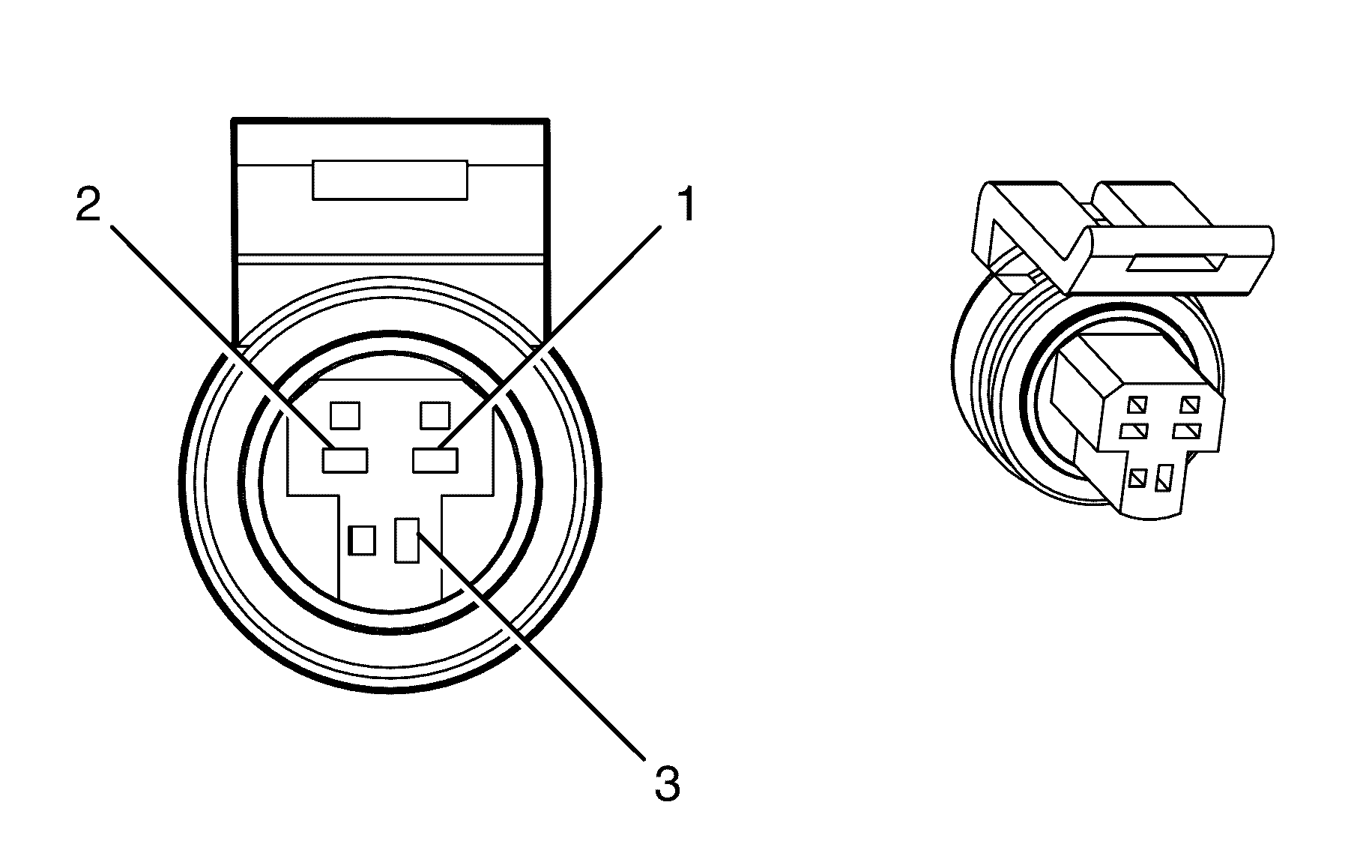
Connector Part Information
|
Terminal Part Information
|
Pin | Wire Color | Circuit No. | Function |
|---|---|---|---|
1 | 0.5 BN/GN | 2759 | Low Reference |
2 | 0.5 GY | 1688 | 5-Volt Reference |
3 | 0.5 OG/BK | 380 | A/C Refrigerant Pressure Sensor Signal |
Accelerator Pedal Position (APP) Sensor
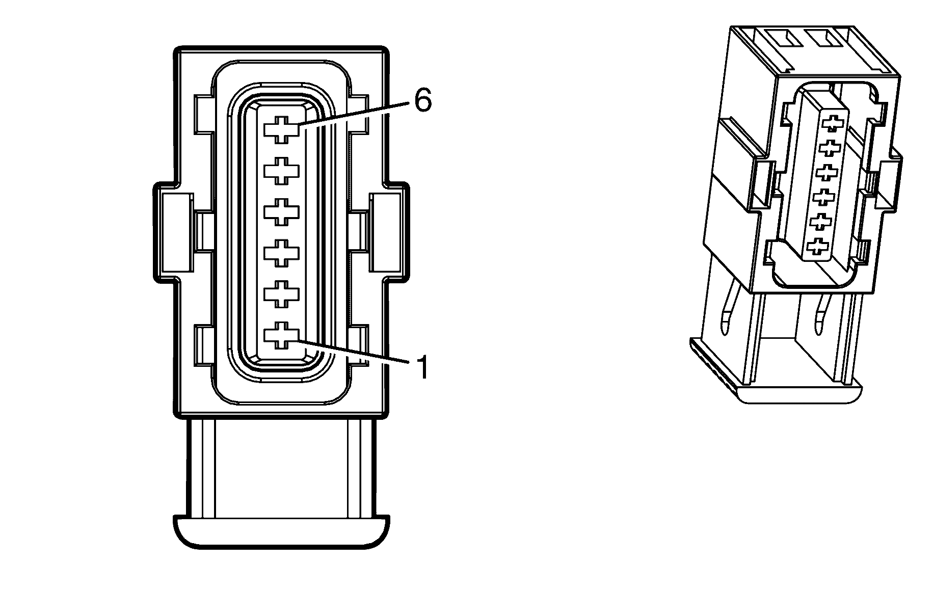
Connector Part Information
|
Terminal Part Information
|
Pin | Wire Color | Circuit No. | Function |
|---|---|---|---|
1 | 0.5 BN/YE | 1274 | 5-Volt Reference |
2 | 0.5 WH/BK | 1164 | 5-Volt Reference |
3 | 0.5 D-BU/WH | 1161 | APP Sensor 1 Signal |
4 | 0.5 BN | 1271 | Low Reference |
5 | 0.5 PU | 1272 | Low Reference |
6 | 0.5 L-BU | 1162 | APP Sensor 2 Signal |
Accessory Power Outlet - Center Console Compartment
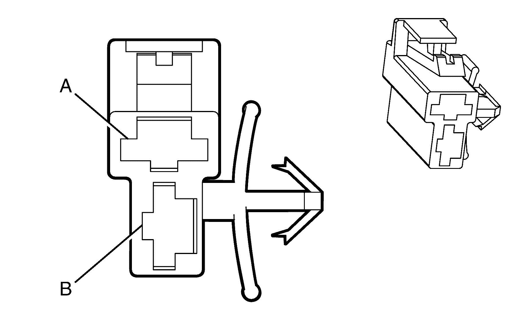
Connector Part Information
|
Terminal Part Information
|
Pin | Wire Color | Circuit No. | Function |
|---|---|---|---|
A | 1.25 D-GN | 9301 | Accessory Voltage |
B | 1.25 BK | 2050 | Ground |
Accessory Power Outlet - I/P

Connector Part Information
|
Terminal Part Information
|
Pin | Wire Color | Circuit No. | Function |
|---|---|---|---|
1 | 1.25 D-GN | 9301 | Accessory Voltage |
2 | 1.25 BK | 850 | Ground |
Air Temperature Actuator (C60)
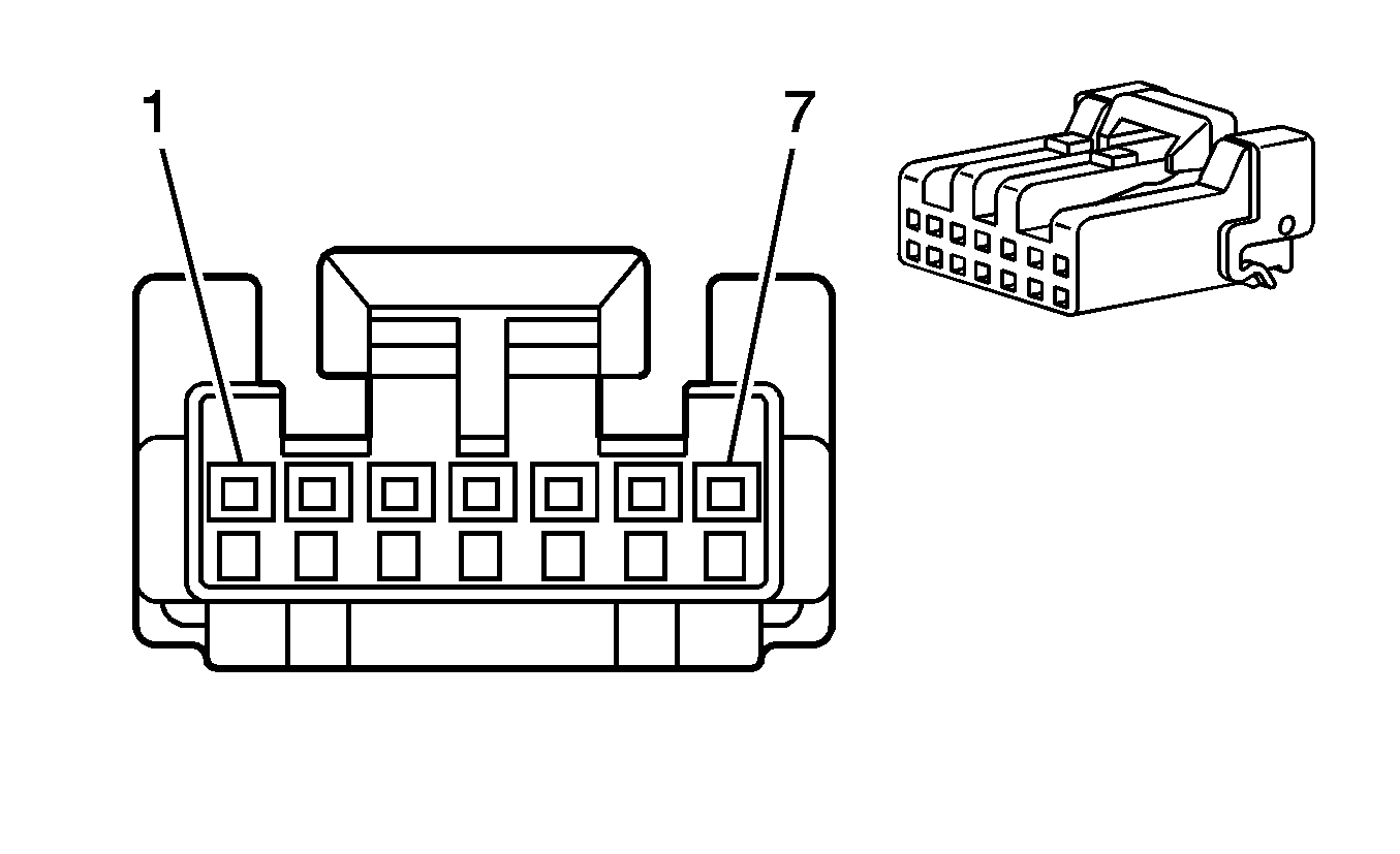
Connector Part Information
|
Terminal Part Information
|
Pin | Wire Color | Circuit No. | Function |
|---|---|---|---|
1 | 0.5 YE | 598 | 5-Volt Reference |
2 | -- | -- | Not Used |
3 | 0.5 GY | 1791 | Low Reference |
4 | -- | -- | Not Used |
5 | 0.5 WH | 733 | Air Temperature Door Position Signal |
6 | 0.5 D-BU/WH | 5954 | Air Temperature Motor Control |
7 | 0.5 RD/WH | 2210 | Air Temperature Door Control |
Air Temperature Actuator - Left (CJ2)

Connector Part Information
|
Terminal Part Information
|
Pin | Wire Color | Circuit No. | Function |
|---|---|---|---|
1 | 0.5 YE | 598 | 5-Volt Reference |
2 | -- | -- | Not Used |
3 | 0.5 GY | 1791 | Low Reference |
4 | -- | -- | Not Used |
5 | 0.5 WH | 733 | Air Temperature Door Position Signal |
6 | 0.5 D-BU/WH | 5954 | Air Temperature Motor Control |
7 | 0.5 RD/WH | 2210 | Air Temperature Door Control |
Air Temperature Actuator - Right (CJ2)

Connector Part Information
|
Terminal Part Information
|
Pin | Wire Color | Circuit No. | Function |
|---|---|---|---|
1 | 0.5 YE | 598 | 5-Volt Reference |
2 | -- | -- | Not Used |
3 | 0.5 GY | 1791 | Low Reference |
4 | -- | -- | Not Used |
5 | 0.5 L-GN | 1646 | Driver Air Temperature Door Control A |
6 | 0.5 BN | 2778 | Right Air Temperature Door Control A |
7 | 0.5 WH/BK | 1236 | Auxiliary Air Temperature Door Control |
Air Temperature Sensor
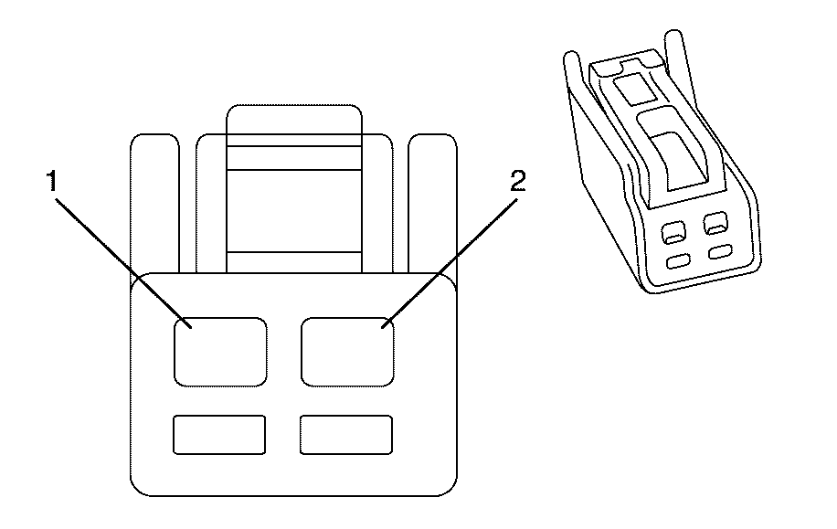
Connector Part Information
|
Terminal Part Information
|
Pin | Wire Color | Circuit No. | Function |
|---|---|---|---|
A | 0.5 GY | 1791 | Low Reference |
B | 0.5 GY | 1199 | Air Temperature Door Control |
Air Temperature Sensor - Inside
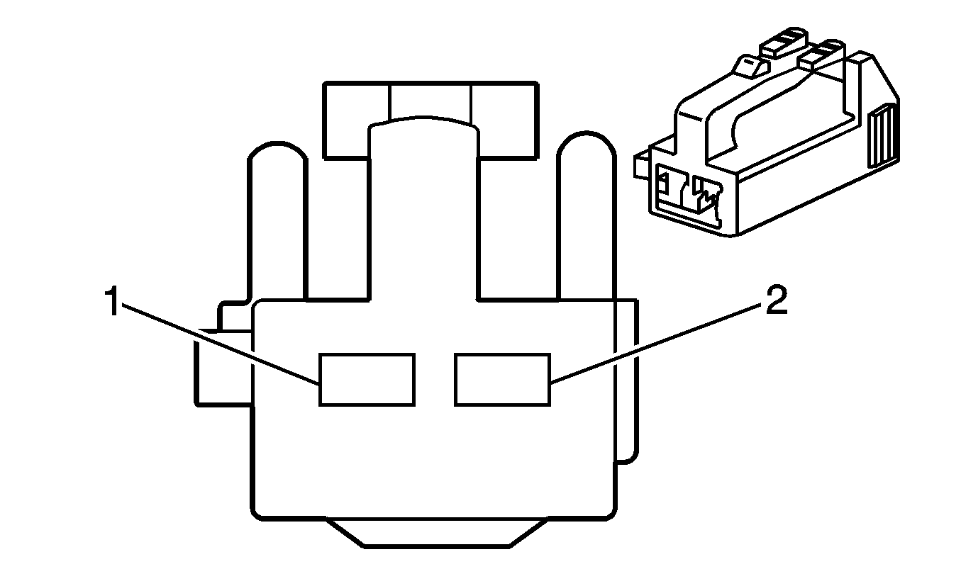
Connector Part Information
|
Terminal Part Information
|
Pin | Wire Color | Circuit No. | Function |
|---|---|---|---|
A | 0.3 D-GN | 734 | Inside Ambient Temperature Sensor Low Reference |
B | 0.3 BN | 61 | Outside Air Temperature Sensor Signal |
Ambient Air Temperature Sensor
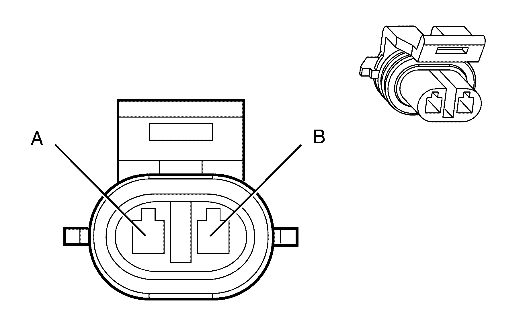
Connector Part Information
|
Terminal Part Information
|
Pin | Wire Color | Circuit No. | Function |
|---|---|---|---|
A | 0.3 BN | 61 | Low Reference |
B | 0.3 L-GN/BK | 735 | 5-Volt Reference |
Ambient Light Sensor (C60)
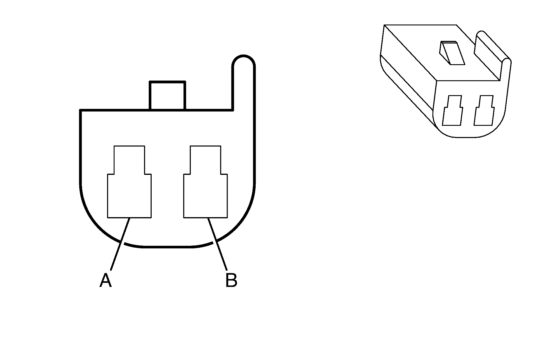
Connector Part Information
|
Terminal Part Information
|
Pin | Wire Color | Circuit No. | Function |
|---|---|---|---|
A | 0.3 L-GN/BK | 1137 | DRL Ambient Light Sensor Signal |
B | 0.3 BK | 850 | Ground |
Audio Amplifier (UWP)
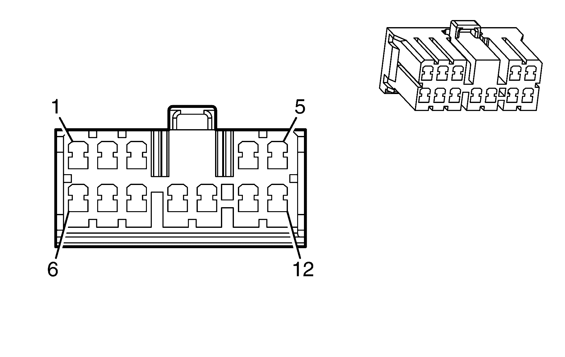
Connector Part Information
|
Terminal Part Information
|
Pin | Wire Color | Circuit No. | Function |
|---|---|---|---|
1 | 0.5 BN | 199 | Left Rear Speaker Output (+) |
2 | 0.5 D-BU | 46 | Right Rear Speaker Output (+) |
3 | 1.25 D-BU/WH | 346 | Left Subwoofer Speaker Output (+) |
4 | 1.25 OG/WH | 2040 | Battery Positive Voltage |
5 | 1.25 BK | 2050 | Ground |
6 | 0.5 YE/RD | 116 | Left Rear Speaker Output (-) |
7 | 0.5 L-BU | 115 | Right Rear Speaker Output (-) |
8 | 1.25 L-GN/BK | 1794 | Left Subwoofer Speaker Output (-) |
9 | 1.25 D-GN | 1795 | Right Subwoofer Speaker Output (+) |
10 | 1.25 L-BU/BK | 315 | Right Subwoofer Speaker Output (-) |
11 | 1.25 OG/WH | 2040 | Battery Positive Voltage |
12 | 1.25 BK | 2050 | Ground |
Automatic Transmission (MYC)
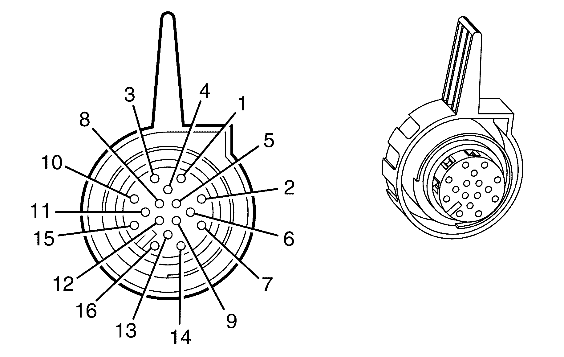
Connector Part Information
|
Terminal Part Information
|
Pin | Wire Color | Circuit No. | Function |
|---|---|---|---|
1 | 0.75 OG/YE | 3640 | Battery Positive Voltage |
2 | 0.75 BK | 450 | Ground |
3 | 0.5 OG/BK | 1786 | Park/Neutral Signal |
4 | 0.75 OG/YE | 3640 | Battery Positive Voltage |
5 | 0.75 BK | 450 | Ground |
6 | 0.5 WH/BU | 17 | Stop Lamp Switch Signal |
7-8 | -- | -- | Not Used |
9 | 0.5 D-BU | 5985 | Accessory Wakeup Serial Data |
10 | 0.5 BN/BK | 9002 | High Speed GMLAN Serial Data Bus+ |
11 | 0.5 BN | 9003 | High Speed GMLAN Serial Data Bus- |
12 | 0.5 PK | 439 | Ignition 1 Voltage |
13 | 0.5 BN | 9001 | High Speed GMLAN Serial Data Bus- |
14 | 0.5 BN/BK | 9000 | High Speed GMLAN Serial Data Bus+ |
15-16 | -- | -- | Not Used |
Automatic Transmission Input Shaft Speed (ISS) Sensor
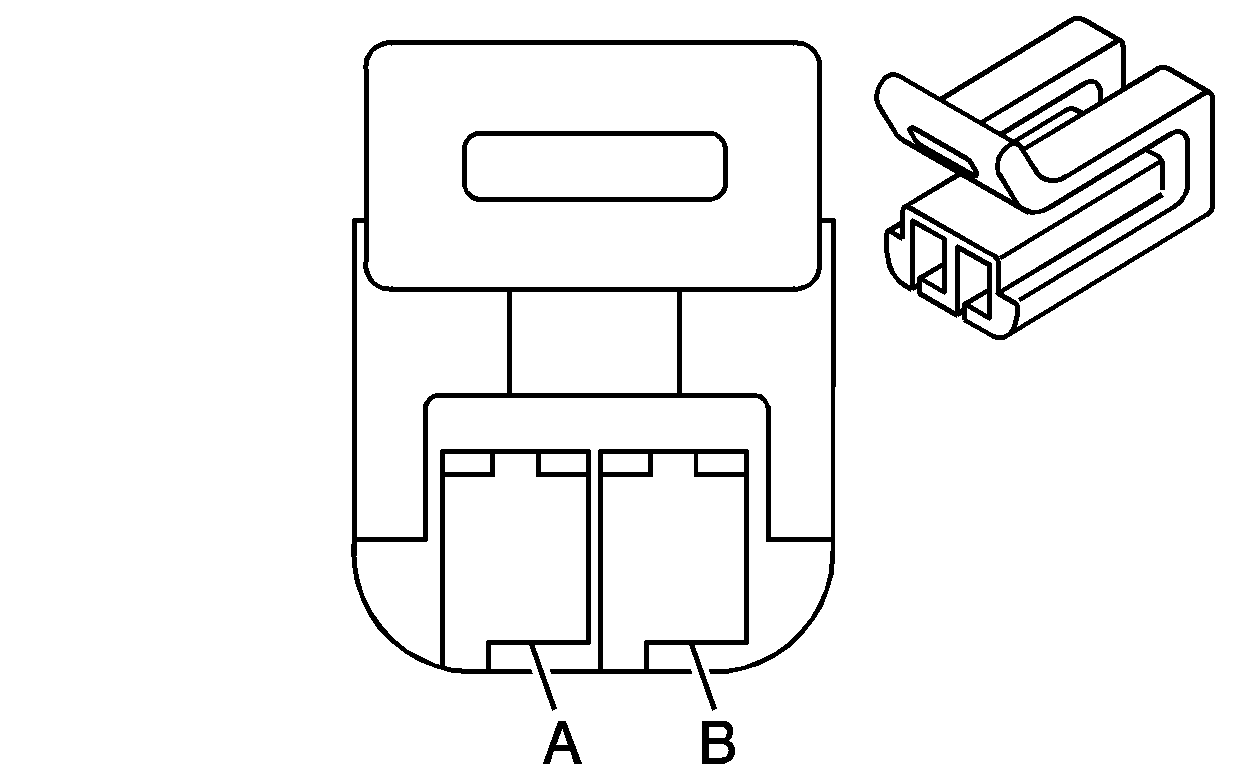
Connector Part Information
|
Terminal Part Information
|
Pin | Wire Color | Circuit No. | Function |
|---|---|---|---|
A | 0.5 YE | 1983 | Transmission Turbine Speed Switch Signal |
B | 0.5 WH | 1984 | Transmission Turbine Speed Switch Low Reference |
Automatic Transmission Output Shaft Speed (OSS) Sensor

Connector Part Information
|
Terminal Part Information
|
Pin | Wire Color | Circuit No. | Function |
|---|---|---|---|
A | 0.5 OG | 822 | VSS Low Signal |
B | 0.5 WH | 821 | VSS High Signal |
Automatic Transmission Shift Lever
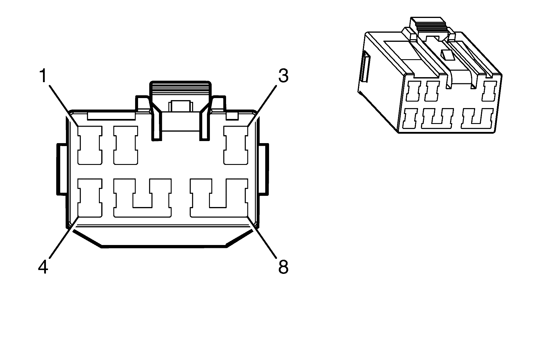
Connector Part Information
|
Terminal Part Information
|
Pin | Wire Color | Circuit No. | Function |
|---|---|---|---|
1 | 0.3 PU | 1375 | Transmission Cruise Switch Reference |
2 | 0.3 D-GN/WH | 1135 | A/T Shift Lock Control Solenoid Supply Voltage |
3 | 0.3 BK | 850 | Ground |
4 | 0.3 PU/RD | 5526 | Transmission Range Select Reference |
5 | -- | -- | Not Used |
6 | 0.3 PU/WH | 1630 | Steering Column Key Cylinder Lock Solenoid Control |
7 | -- | -- | Not Used |
8 | 0.3 YE | 6817 | LED Backlight Diming Control |
Backup Lamp - Left
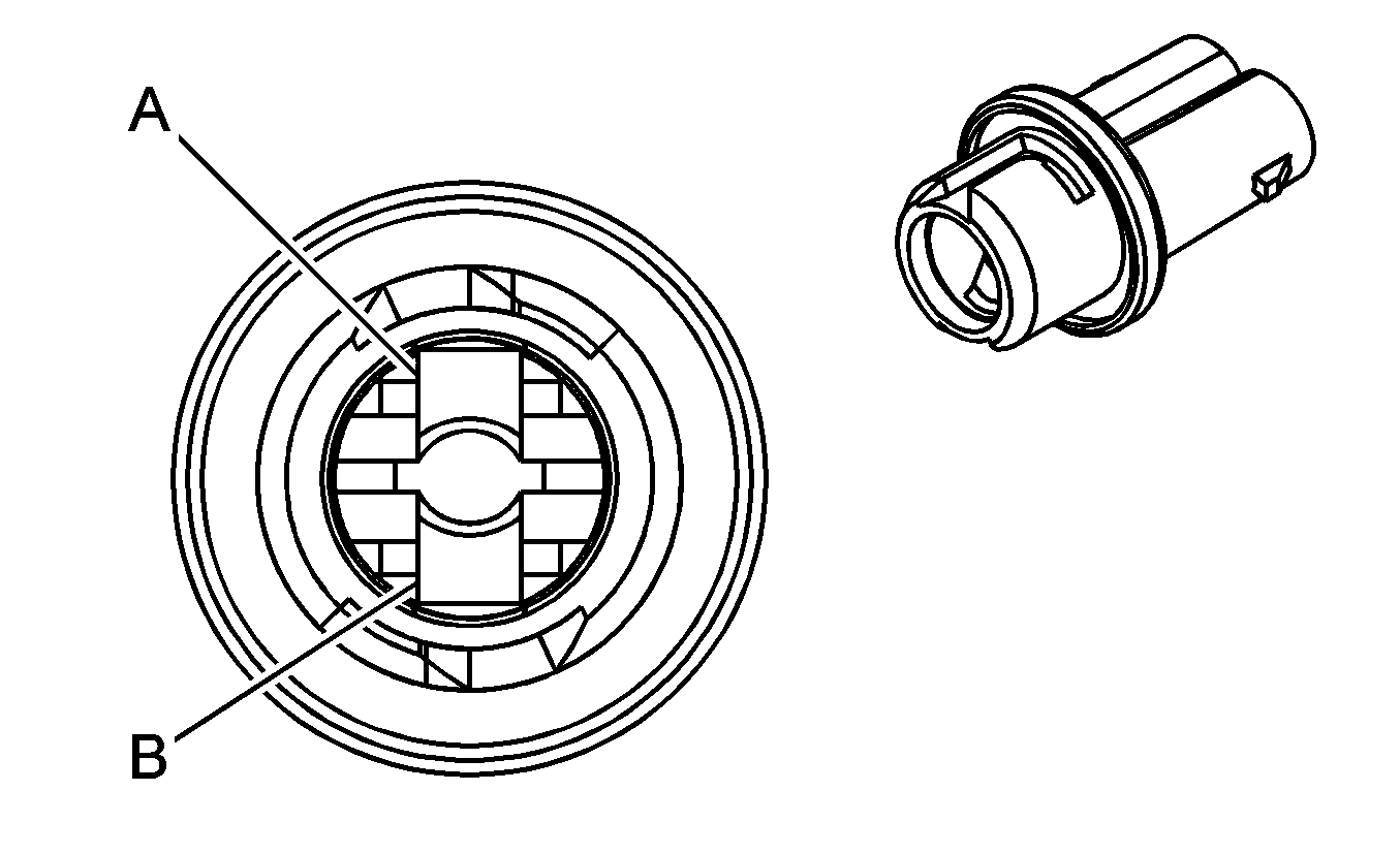
Connector Part Information
|
Terminal Part Information
|
Pin | Wire Color | Circuit No. | Function |
|---|---|---|---|
1 | 0.85 L-GN | -- | Backup Lamp Supply Voltage |
2 | 0.85 BK | -- | Ground |
Backup Lamp - Right

Connector Part Information
|
Terminal Part Information
|
Pin | Wire Color | Circuit No. | Function |
|---|---|---|---|
1 | 0.85 L-GN | -- | Backup Lamp Supply Voltage |
2 | 0.85 BK | -- | Ground |
Battery (-)
Terminal Part Information
|
Pin | Wire Color | Circuit No. | Function |
|---|---|---|---|
- | 50 BK | 50 | Ground |
Battery (+)
Terminal Part Information
|
Pin | Wire Color | Circuit No. | Function |
|---|---|---|---|
+ | 50 RD | 1 | Battery Positive |
Battery Current Sensor
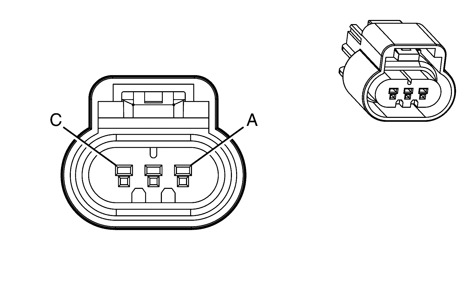
Connector Part Information
|
Terminal Part Information
|
Pin | Wire Color | Circuit No. | Function |
|---|---|---|---|
A | 0.3 PK | 5076 | 5-Volt Reference |
B | 0.3 BN | 5077 | Low Reference |
C | 0.3 WH/GN | 5075 | Battery Current Signal |
Blower Motor
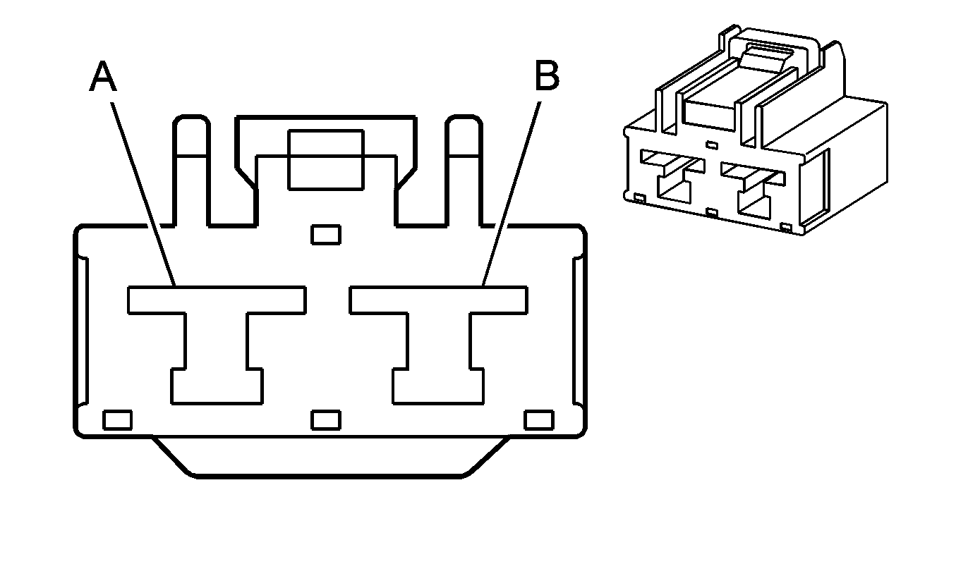
Connector Part Information
|
Terminal Part Information
|
Pin | Wire Color | Circuit No. | Function |
|---|---|---|---|
A | 3 OG | 5987 | Ground |
B | 3 PU | 65 | Blower Motor Supply Voltage |
Blower Motor Control Module
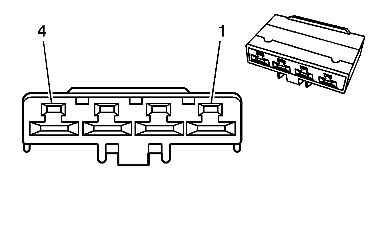
Connector Part Information
|
Terminal Part Information
|
Pin | Wire Color | Circuit No. | Function |
|---|---|---|---|
1 | 3 BK | 850 | Ground |
2 | 0.5 GY/BK | 754 | Blower Motor Speed Control |
3 | 3 PU | 65 | Blower Motor Supply Voltage |
4 | 3 OG | 5987 | Blower Motor Low Reference |
Body Control Module (BCM) X1
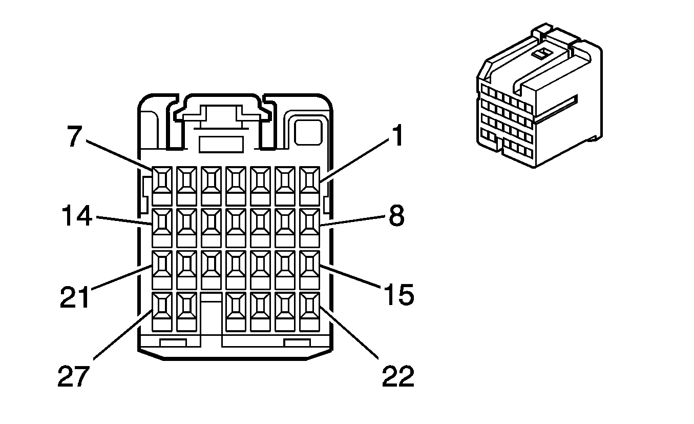
Connector Part Information
|
Terminal Part Information
|
Pin | Wire Color | Circuit No. | Function |
|---|---|---|---|
1 | -- | -- | Not Used |
2 | 0.3 WH | 1390 | Ignition Key Resistor Low Reference |
3 | 0.5 GY | 1884 | Cruise Control Switch Signal |
4 | 0.3 WH/BK | 1073 | Ignition Key Resistor Signal |
5 | 0.3 L-GN | 1715 | Windshield Wiper Switch High Signal |
6-7 | -- | -- | Not Used |
8 | 0.3 BK/WH | 1251 | Wiper Switch Low Reference |
9 | 0.3 L-BU | 1714 | Windshield Wiper Switch Low Signal |
10-13 | -- | -- | Not Used |
14 | 0.3 PK | 3 | Run/Crank Voltage |
15 | 0.3 L-BU/WH | 1414 | Left Turn Signal Switch Signal |
16 | 0.3 D-BU/WH | 1415 | Right Turn Signal Switch Signal |
17 | 0.3 PU | 1375 | Remote Radio Control Supply Voltage |
18 | PU/YE | 524 | Headlamp Dimmer Switch High Beam Signal |
19 | 0.3 WH/RD | 6821 | Dome Lamp Supply Voltage |
20 | 0.3 PU/RD | 5526 | Transmission Electronic Range Select Signal |
21 | 0.3 BN | 4 | Ignition 1 Voltage |
22-23 | -- | -- | Not Used |
24 | 0.3 OG | 94 | Windshield Washer Switch Signal |
25 | 0.3 BN/RD | 1356 | Flash To Pass Switch Signal |
26-27 | -- | -- | Not Used |
Body Control Module (BCM) X2
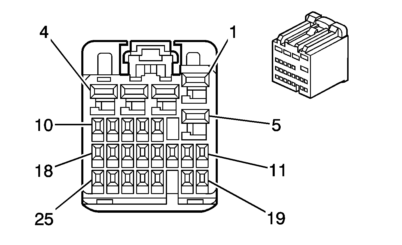
Connector Part Information
|
Terminal Part Information
|
Pin | Wire Color | Circuit No. | Function |
|---|---|---|---|
1 | 0.85 OG | 1732 | Inadvertent Power Supply Voltage |
2 | 0.85 OG/BU | 1240 | Battery Positive Voltage |
3 | 0.85 GY | 8 | Instrument Panel Lamp Supply Voltage |
4 | -- | -- | Not Used |
5 | 0.85 D-BU/WH | 149 | Courtesy Lamp Supply Voltage |
6-7 | -- | -- | Not Used |
8 | 0.3 BN/WH | 301 | Park Lamp Switch On Signal |
9 | -- | -- | Not Used |
10 | 0.3 D-BU | 6189 | Rear Compartment Relay Switch |
11 | 0.3 L-GN/BK | 1137 | DRL Ambient Light Sensor Signal |
12 | 0.3 WH | 103 | Headlamp Switch Headlamps On Signal |
13-16 | -- | -- | Not Used |
17 | 0.3 D-GN | 306 | Headlamp Switch Headlamps Off Signal |
18 | 0.3 PK/BK | 1597 | Courtesy Lamps Switch Signal |
19-20 | -- | -- | Not Used |
21 | 0.3 BN/OG | 1571 | Traction Control Switch Signal |
22 | 0.3 D-GN/WH | 1135 | A/T Shift Lock Control Solenoid Supply Voltage |
23-24 | -- | -- | Not Used |
25 | 0.3 PU | 328 | Interior Lamp Switch Signal |
Body Control Module (BCM) X3
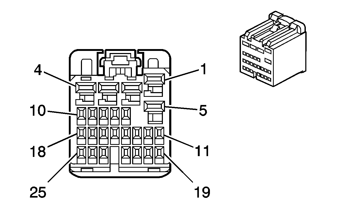
Connector Part Information
|
Terminal Part Information
|
Pin | Wire Color | Circuit No. | Function |
|---|---|---|---|
1 | 0.85 BK | 850 | Ground |
2 | 0.85 OG/YE | 1640 | Battery Positive Voltage |
3 | 0.85 OG/RD | 2740 | Battery Positive Voltage |
4 | -- | -- | Not Used |
5 | 0.85 BK | 850 | Ground |
6 | -- | -- | Not Used |
7 | 0.3 GY | 728 | Security Indicator Control |
8 | 0.5 BN/BK | 9004 | High Speed GMLAN Serial Data Bus+ |
9 | 0.5 BN | 9005 | High Speed GMLAN Serial Data Bus- |
10 | D-GN | 9208 | Low Speed GMLAN Serial Data |
11-12 | -- | -- | Not Used |
13 | 0.5 L-GN | 526 | Stop Lamp Switch Signal |
14 | 0.5 BN/RD | 552 | Low Reference |
15 | 0.5 GY | 598 | 5-Volt Reference |
16 | 0.5 BN/BK | 9006 | High Speed GMLAN Serial Data Bus+ |
17 | 0.5 BN | 9007 | High Speed GMLAN Serial Data Bus- |
18 | 0.3 YE | 6817 | LED Backlight Dimming Control |
19 | 0.3 PU/WH | 5727 | Communication Enable Relay Control |
20 | -- | -- | Not Used |
21 | 0.3 OG | 192 | Fog Lamp Switch |
22-24 | -- | -- | Not Used |
25 | 0.3 PU/WH | 6816 | Heated Seat Supply Voltage (KA1) |
Body Control Module (BCM) X4
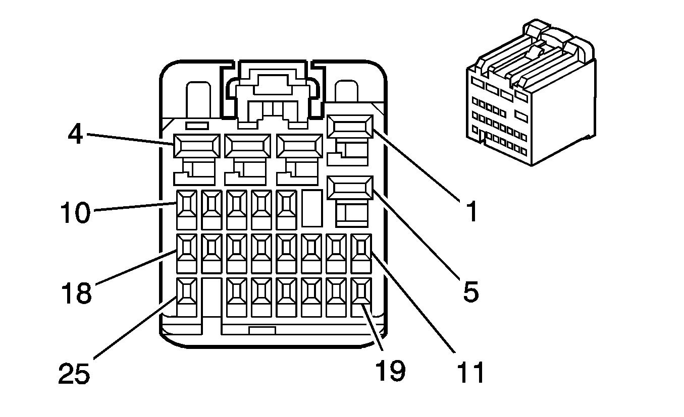
Connector Part Information
|
Terminal Part Information
|
Pin | Wire Color | Circuit No. | Function |
|---|---|---|---|
1 | 0.85 OG/RD | 340 | Battery Positive Voltage |
2 | 0.85 OG | 240 | Battery Positive Voltage |
3 | 0.85 OG/GN | 440 | Battery Positive Voltage |
4 | 0.85 OG/PU | 2140 | Battery Positive Voltage |
5 | 0.75 D-BU/WH | 1315 | Right Front Turn Signal Lamp Supply Voltage |
6 | -- | -- | Not Used |
7 | 0.3 YE | 196 | Windshield Wiper Motor Park Switch Signal |
8 | -- | -- | Not Used |
9 | 0.3 BK | 1850 | Ground |
10 | 0.3 OG/BU | 2440 | Battery Positive Voltage |
11 | 0.3 D-GN/WH | 1317 | Fog Lamp Relay Control |
12-14 | -- | -- | Not Used |
15 | 0.5 OG | 2268 | Washer Fluid Pump Relay Control |
16 | 0.3 BN/YE | 1969 | Headlamp High Beam Relay Control |
17 | 0.3 PK/BK | 109 | Hood Ajar Switch Signal |
18 | -- | -- | Not Used |
19 | 0.3 D-BU | 5985 | Accessory Wakeup Serial Data |
20 | -- | -- | Not Used |
21 | 0.3 PK | 1439 | Run/Crank Control |
22 | 0.3 BN | 253 | Trunk Release Relay Control |
23 | 0.3 PU | 544 | Headlamp Low Beam Supply Voltage |
24 | 0.3 D-GN | 646 | Backup Lamp Relay Control |
25 | -- | -- | Not Used |
Body Control Module (BCM) X5
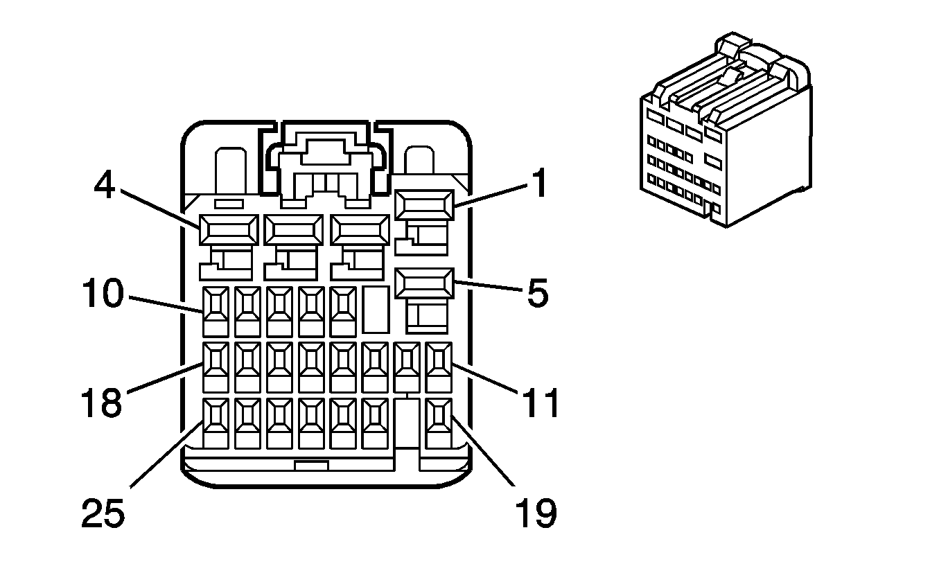
Connector Part Information
|
Terminal Part Information
|
Pin | Wire Color | Circuit No. | Function |
|---|---|---|---|
1 | 0.85 YE/BK | 1334 | Left Rear Turn Signal Lamp Supply Voltage |
2 | 0.85 D-GN/WH | 1335 | Right Rear Turn Signal Lamp Supply Voltage |
3 | -- | -- | Not Used |
4 | 0.75 L-BU/WH | 1314 | Left Front Turn Signal Lamp Supply |
5 | -- | -- | Not Used |
6 | 0.5 WH/BU | 17 | Stop Lamp Switch Signal |
7 | -- | -- | Not Used |
8 | 0.3 PK | 5076 | 5-Volt Reference |
9 | 0.3 WH/GN | 5075 | Battery Current Signal |
10 | 0.3 BN | 5077 | Low Reference |
11 | 0.3 BN/YE | 707 | RAP Relay Coil Supply Voltage |
12-13 | -- | -- | Not Used |
14 | 0.3 YE | 43 | Accessory Power Relay Control |
15 | 0.3 PU | 5531 | Hood Closed Switch Signal |
16 | 0.5 OG/BK | 233 | Park Brake Switch Signal |
17 | -- | -- | Not Used |
18 | 0.3 BN/BK | 28 | Horn Relay Control |
19 | -- | -- | Not Used |
20 | 0.3 GY | 91 | Windshield Wiper Switch Signal 2 |
21 | 0.3 BN/RD | 860 | Front Windshield Wiper Switch High Signal |
22 | -- | -- | Not Used |
23 | 0.3 PK/WH | 1970 | Headlamp Low Beam Relay Control |
24 | 0.3 WH/YE | 1080 | Park Lamp Relay Control |
25 | -- | -- | Not Used |
Body Control Module (BCM) X6
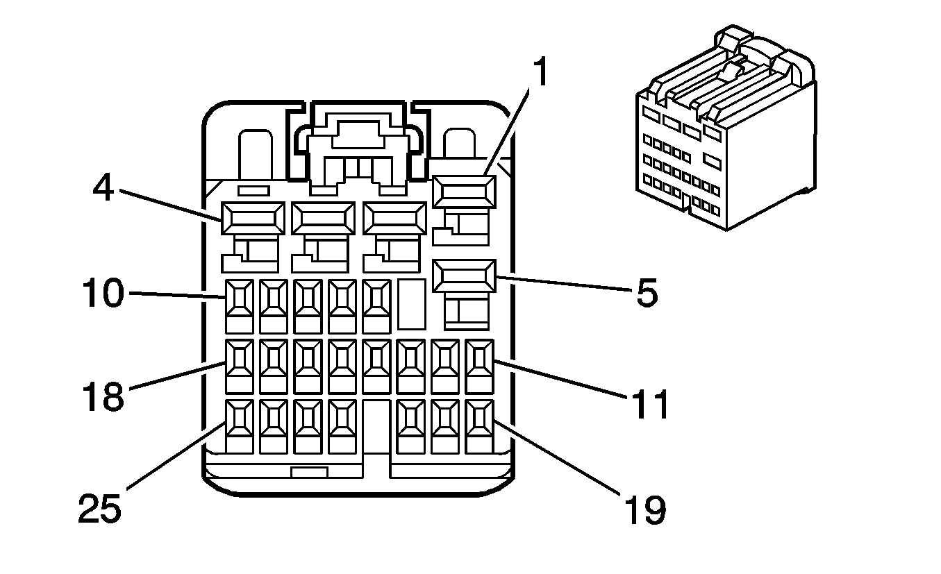
Connector Part Information
|
Terminal Part Information
|
Pin | Wire Color | Circuit No. | Function |
|---|---|---|---|
1 | -- | -- | Not Used |
2 | 1.25 L-BU | 20 | Stop Lamp Supply Voltage |
3-7 | -- | -- | Not Used |
8 | 0.3 BN/WH | 746 | Passenger Front Door Ajar Switch Signal |
9 | -- | -- | Not Used |
10 | 0.3 GY/BK | 745 | Driver Door Ajar Switch Signal |
11-19 | -- | -- | Not Used |
20 | 0.3 PK | 781 | Driver Door Lock Switch Unlock Signal |
21 | -- | -- | Not Used |
22 | 0.3 OG/BK | 744 | Liftgate Ajar Switch Signal |
23 | 0.3 PK/BK | 780 | Driver Door Lock Switch Lock Signal |
24-25 | -- | -- | Not Used |
Body Control Module (BCM) X7
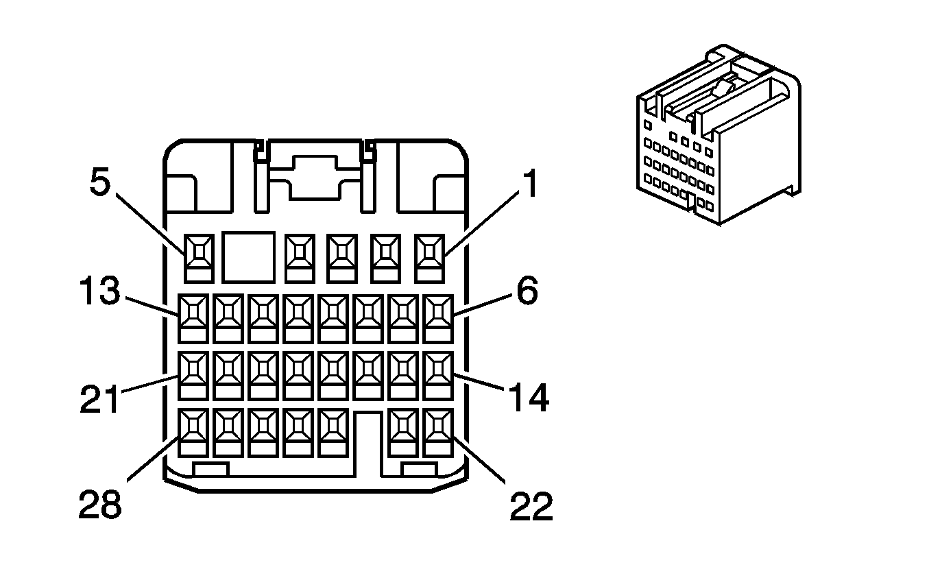
Connector Part Information
|
Terminal Part Information
|
Pin | Wire Color | Circuit No. | Function |
|---|---|---|---|
1-5 | -- | -- | Not Used |
6 | 0.3 L-BU | 5921 | Door Unlock Supply Voltage |
7 | 0.3 D-BU/WH | 195 | Door Lock Control |
8 | -- | -- | Not Used |
9 | 0.3 WH | 194 | Door Unlock Control |
10 | 0.3 GY/BU | 7388 | Headlamp Dimming Switch Up |
11 | 0.3 BN/BK | 254 | Power Door Unlock Fuse Supply Voltage |
12 | 0.3 GY/BK | 255 | Power Door Lock Fuse Supply Voltage |
13-23 | -- | -- | Not Used |
24 | 0.3 GY/WH | 7389 | Headlamp Dimming Switch Down |
25-28 | -- | -- | Not Used |
Brake Booster Vacuum Sensor (L76)

Connector Part Information
|
Terminal Part Information
|
Pin | Wire Color | Circuit No. | Function |
|---|---|---|---|
1 | 0.5 D-BU | 1809 | Brake Booster Vacuum Sensor Signal |
2 | 0.5 L-GN/BK | 6258 | Brake Booster Vacuum Low Reference |
3 | 0.5 L-GN | 6257 | Brake Booster Vacuum 5-Volt Supply |
Brake Fluid Level Switch
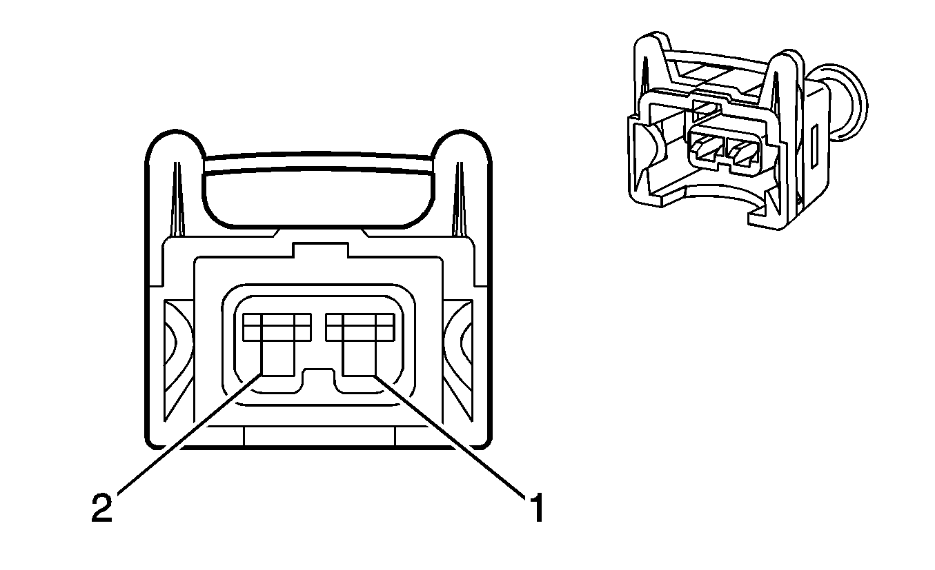
Connector Part Information
|
Terminal Part Information
|
Pin | Wire Color | Circuit No. | Function |
|---|---|---|---|
1 | 0.3 BK | 350 | Ground |
2 | 0.3 BN/WH | 33 | Brake Warning Indicator Control |
Brake Pedal Position (BPP) Sensor
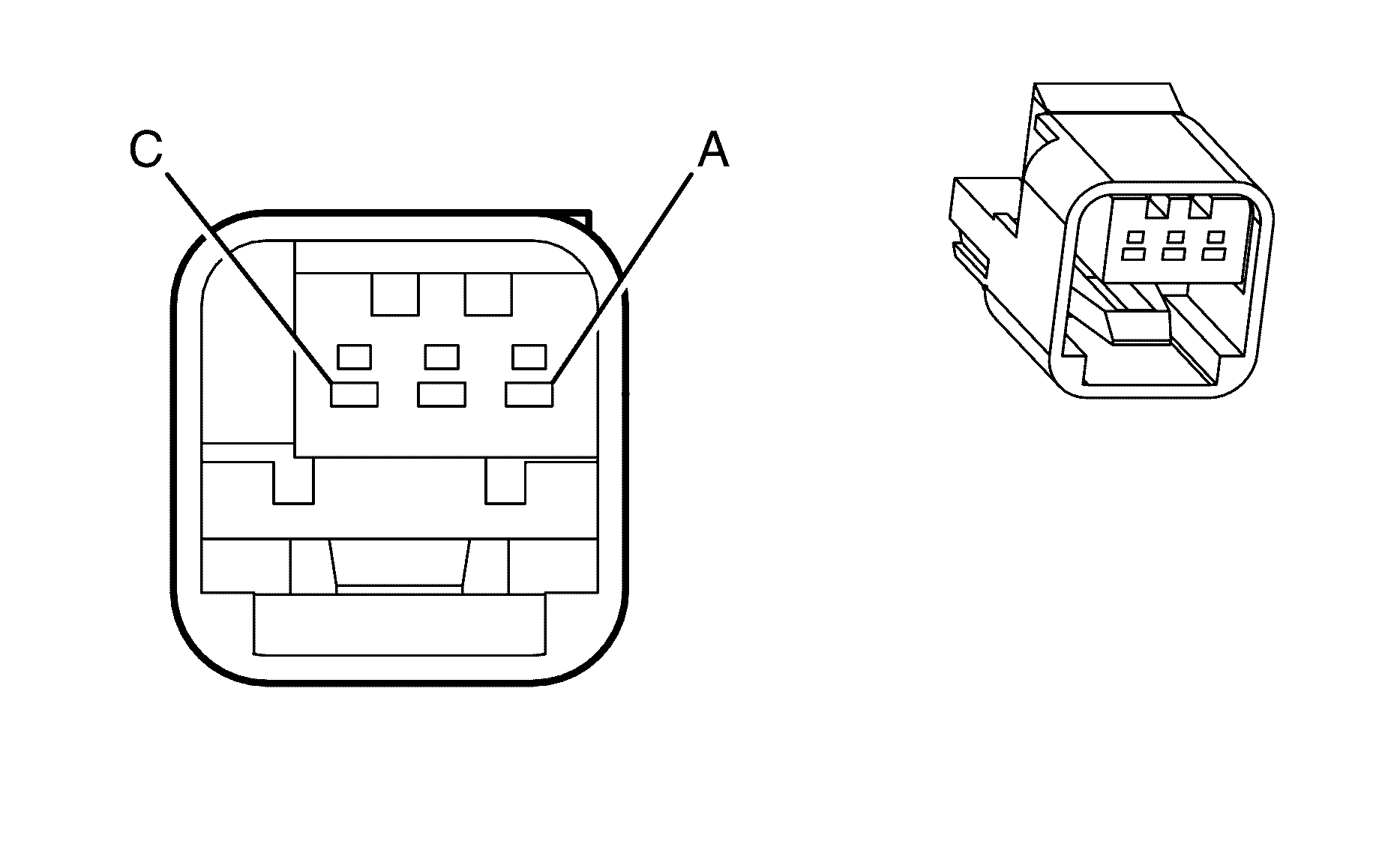
Connector Part Information
|
Terminal Part Information
|
Pin | Wire Color | Circuit No. | Function |
|---|---|---|---|
A | 0.5 GY | 598 | 5-Volt Reference |
B | 0.5 L-GN | 526 | Stop Lamp Switch Signal |
C | 0.5 BN/RD | 552 | Low Reference |
Camshaft Position (CMP) Actuator Solenoid Valve - Bank 1 Exhaust (LY7)
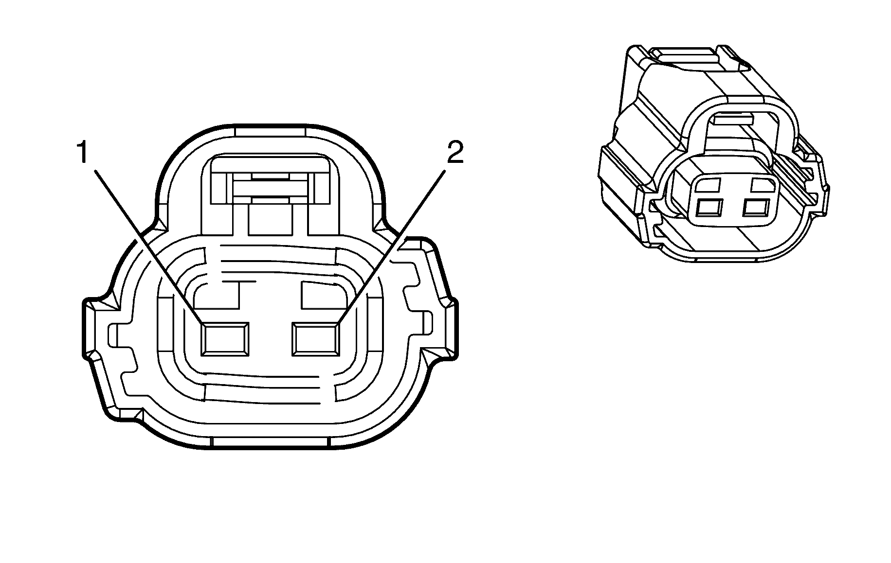
Connector Part Information
|
Terminal Part Information
|
Pin | Wire Color | Circuit No. | Function |
|---|---|---|---|
1 | 0.75 PK/BU | 5293 | Ignition 1 Voltage |
2 | 0.75 L-GN | 5282 | CMP Actuator Solenoid Control - Exhaust Bank 1 |
Camshaft Position (CMP) Actuator Solenoid Valve - Bank 1 Intake (LY7)

Connector Part Information
|
Terminal Part Information
|
Pin | Wire Color | Circuit No. | Function |
|---|---|---|---|
1 | 0.75 PK/BU | 5293 | Ignition 1 Voltage |
2 | 0.75 PU | 5284 | CMP Actuator Solenoid Control - Intake Bank 1 |
Camshaft Position (CMP) Actuator Solenoid Valve - Bank 2 Exhaust (LY7)

Connector Part Information
|
Terminal Part Information
|
Pin | Wire Color | Circuit No. | Function |
|---|---|---|---|
1 | 0.75 PK/BU | 5293 | Ignition 1 Voltage |
2 | 0.75 WH/BK | 5283 | CMP Actuator Solenoid Control - Exhaust Bank 2 |
Camshaft Position (CMP) Actuator Solenoid Valve - Bank 2 Intake (LY7)

Connector Part Information
|
Terminal Part Information
|
Pin | Wire Color | Circuit No. | Function |
|---|---|---|---|
1 | 0.75 PK/BU | 5293 | Ignition 1 Voltage |
2 | 0.75 OG/BK | 5272 | CMP Actuator Solenoid Control - Intake Bank 2 |
Camshaft Position (CMP) Sensor - Bank 1 Exhaust (LY7)
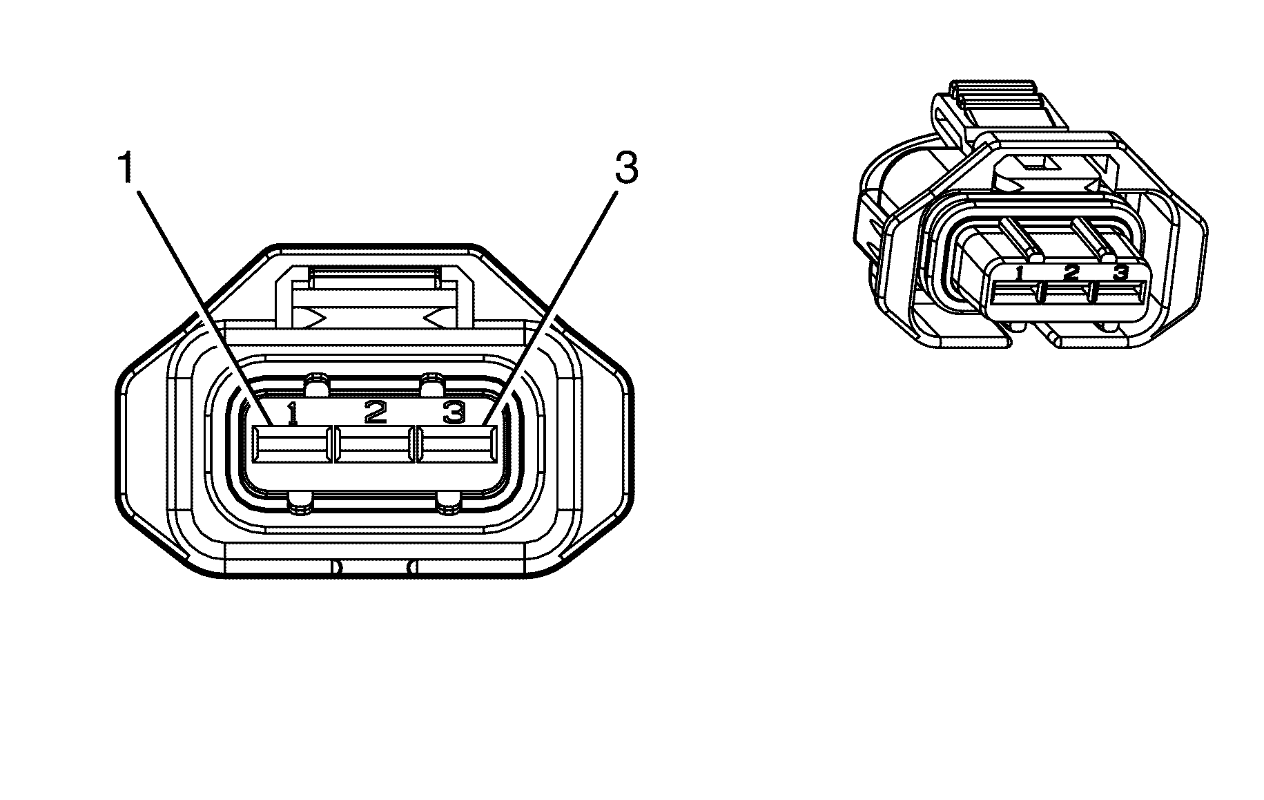
Connector Part Information
|
Terminal Part Information
|
Pin | Wire Color | Circuit No. | Function |
|---|---|---|---|
1 | 0.75 PK/BK | 632 | Low Reference |
2 | 0.5 D-GN | 5273 | CMP Sensor Signal - Exhaust Bank 1 |
3 | 0.75 GY | 705 | 5-Volt Reference |
Camshaft Position (CMP) Sensor - Bank 1 Intake (LY7)

Connector Part Information
|
Terminal Part Information
|
Pin | Wire Color | Circuit No. | Function |
|---|---|---|---|
1 | 0.5 PK/BK | 632 | Low Reference |
2 | 0.5 OG/BU | 5275 | CMP Sensor Signal - Intake Bank 1 |
3 | 0.5 GY | 705 | 5-Volt Reference |
Camshaft Position (CMP) Sensor - Bank 2 Exhaust (LY7)

Connector Part Information
|
Terminal Part Information
|
Pin | Wire Color | Circuit No. | Function |
|---|---|---|---|
1 | 0.5 PK/BK | 632 | Low Reference |
2 | 0.5 PU | 5274 | CMP Sensor Signal - Exhaust Bank 2 |
3 | 0.5 GY | 705 | 5-Volt Reference |
Camshaft Position (CMP) Sensor - Bank 2 Intake (LY7)

Connector Part Information
|
Terminal Part Information
|
Pin | Wire Color | Circuit No. | Function |
|---|---|---|---|
1 | 0.5 PK/BK | 632 | Low Reference |
2 | 0.5 YE/RD | 5276 | CMP Sensor Signal - Intake Bank 2 |
3 | 0.5 GY | 705 | 5-Volt Reference |
Camshaft Position (CMP) Sensor (L76)
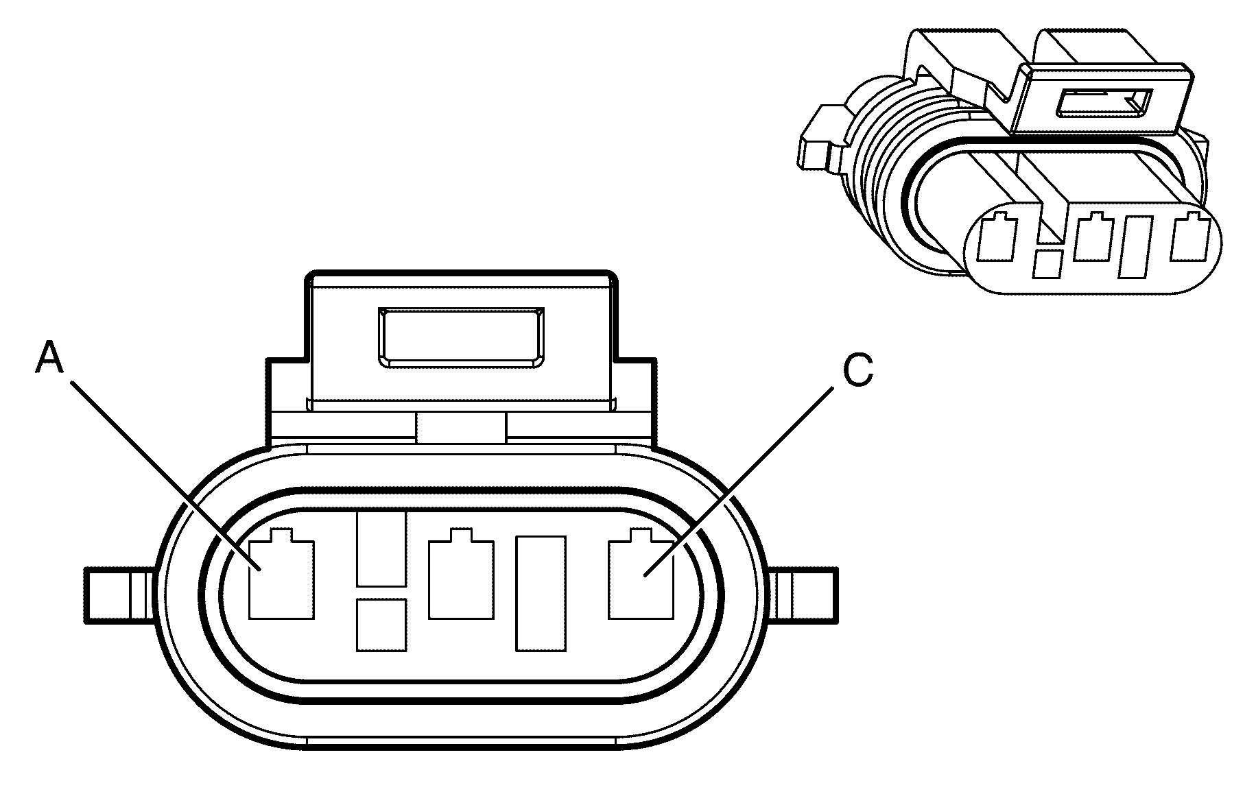
Connector Part Information
|
Terminal Part Information
|
Pin | Wire Color | Circuit No. | Function |
|---|---|---|---|
A | 0.5 OG | 631 | 5-Volt Reference |
B | 0.5 PK/BK | 632 | Low Reference |
C | 0.5 BN/WH | 633 | CMP Sensor Signal |
Center High Mounted Stop Lamp (CHMSL)
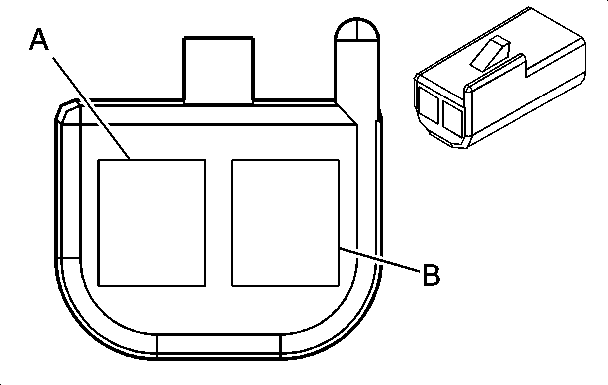
Connector Part Information
|
Terminal Part Information
|
Pin | Wire Color | Circuit No. | Function |
|---|---|---|---|
A | 0.5 L-BU | 20 | Stop Lamp Supply Voltage |
B | 0.5 BK/WH | 851 | Ground |
Crankshaft Position (CKP) Sensor (LY7)
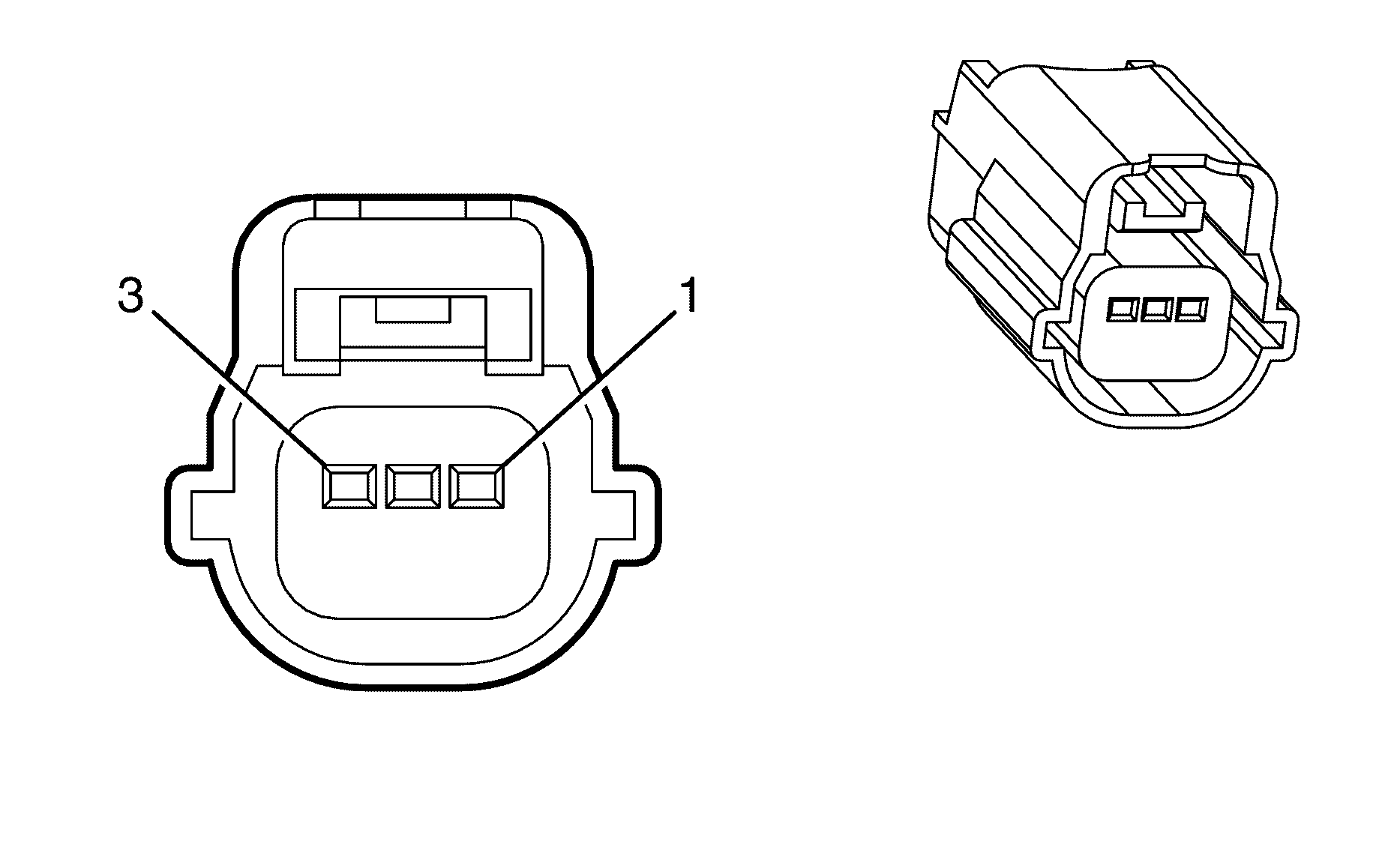
Connector Part Information
|
Terminal Part Information
|
Pin | Wire Color | Circuit No. | Function |
|---|---|---|---|
1 | 0.5 PU | 574 | Low Reference |
2 | 0.5 YE/BU | 573 | CKP Sensor Signal |
3 | 0.5 PU/WH | 605 | 5-Volt Reference |
Crankshaft Position (CKP) Sensor (L76)
Connector Part Information
|
Terminal Part Information
|
Pin | Wire Color | Circuit No. | Function |
|---|---|---|---|
1 | 0.5 D-BU/WH | 1869 | CKP Sensor Signal |
2 | 0.5 YE/BK | 1868 | Low Reference |
3 | 0.5 L-GN | 1867 | 12-Volt Reference |
Data Link Connector (DLC)
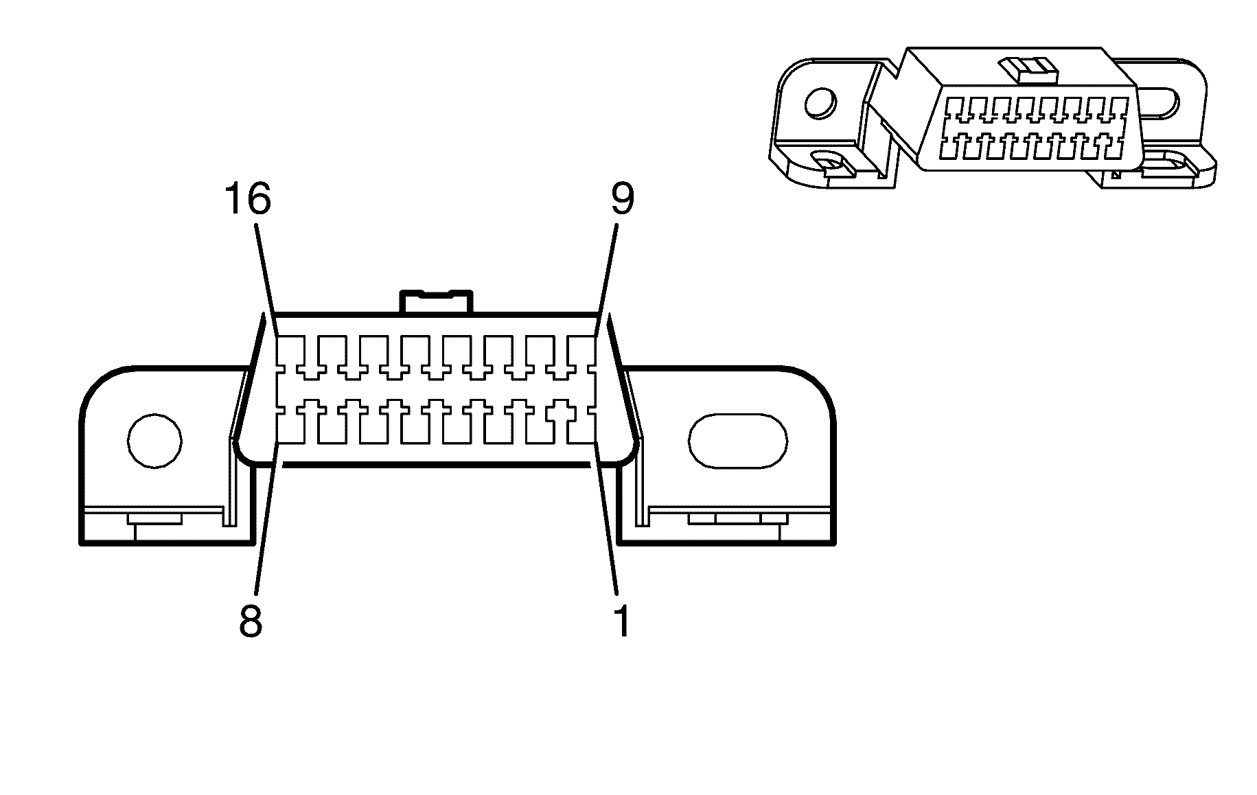
Connector Part Information
|
Terminal Part Information
|
Pin | Wire Color | Circuit No. | Function |
|---|---|---|---|
1 | 0.35 D-GN | 9200 | Low Speed GMLAN Serial Data |
2-3 | -- | -- | Not Used |
4 | 0.3 BK | 850 | Ground |
5 | 0.3 BK | 850 | Ground |
6 | 0.5 BN/BK | 9004 | High Speed GMLAN Serial Data Bus+ |
0.5 BN/BK | 9004 | High Speed GMLAN Serial Data Bus+ | |
7-13 | -- | -- | Not Used |
14 | 0.5 BN | 9005 | High Speed GMLAN Serial Data Bus- |
0.5 BN | 9005 | High Speed GMLAN Serial Data Bus- | |
15 | -- | -- | Not Used |
16 | 0.5 OG/WH | 1840 | Battery Positive Voltage |
Data Link Resistor
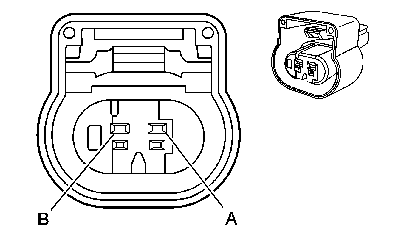
Connector Part Information
|
Terminal Part Information
|
Pin | Wire Color | Circuit No. | Function |
|---|---|---|---|
A | 0.5 BN/BK | 9010 | High Speed GMLAN Serial Data Bus+ |
B | 0.5 BN | 9011 | High Speed GMLAN Serial Data Bus- |
Digital Radio Receiver (U2K)
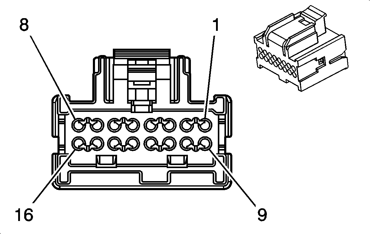
Connector Part Information
|
Terminal Part Information
|
Pin | Wire Color | Circuit No. | Function |
|---|---|---|---|
1 | 0.5 BN/WH | 372 | Remote Radio Audio Output (-) |
2 | 0.5 D-GN | 7007 | Left Radio Audio Output |
3 | 0.5 GY/BK | 7008 | Right Radio Audio Output |
4 | 0.5 GY | 388 | Remote Radio Right Audio Signal |
5 | 0.35 D-GN | 9213 | -- |
6-8 | -- | -- | Not Used |
9 | 0.5 BN | 1050 | Ground |
10-15 | -- | -- | Not Used |
16 | 0.5 OG/WH | 2340 | Battery Positive Voltage |
Dome/Reading Lamps - Front (without CF5)
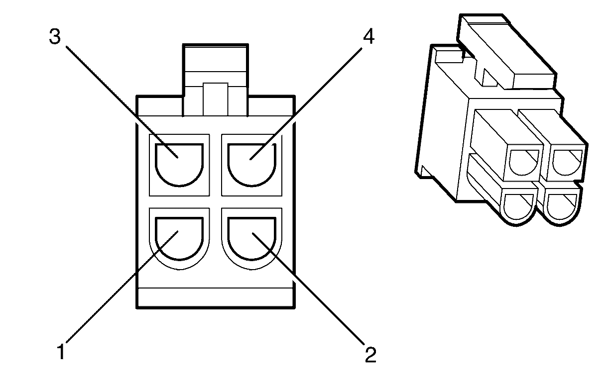
Connector Part Information
|
Terminal Part Information
|
Pin | Wire Color | Circuit No. | Function |
|---|---|---|---|
1 | 0.5 BK/WH | 851 | Ground |
2 | 0.3 PK/BK | 1597 | Courtesy Lamps Switch on signal |
3 | 0.3 PU | 328 | Interior Lamp Switch Signal |
4 | 0.5 D-BU/WH | 149 | Courtesy Lamp Supply Voltage |
Dome/Reading Lamps - Rear

Connector Part Information
|
Terminal Part Information
|
Pin | Wire Color | Circuit No. | Function |
|---|---|---|---|
1 | 0.5 BK/WH | 851 | Ground |
2 | 0.5 D-BU/WH | 149 | Courtesy Lamp Supply Voltage |
3-4 | -- | -- | Not Used |
Door Latch - Driver
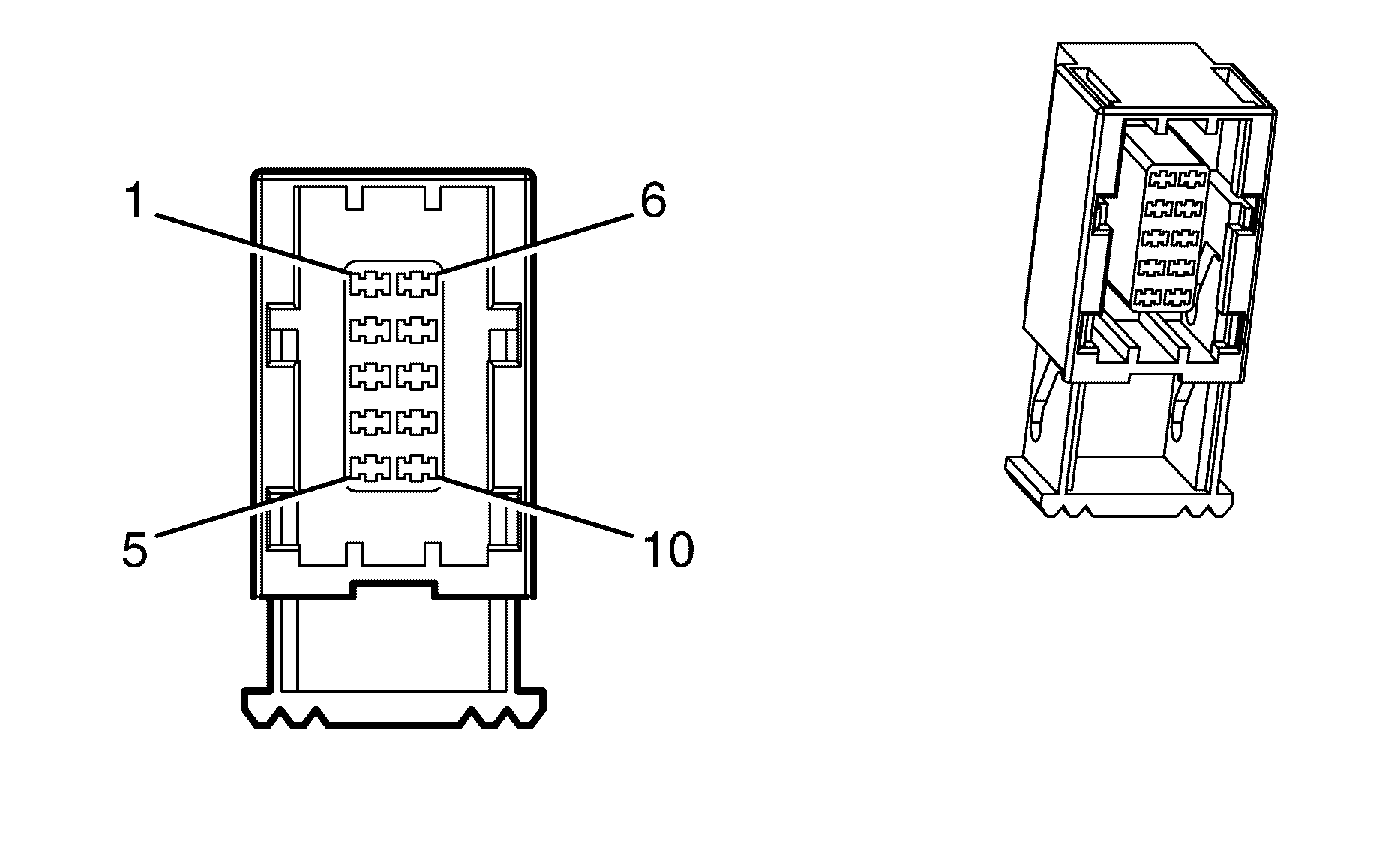
Connector Part Information
|
Terminal Part Information
|
Pin | Wire Color | Circuit No. | Function |
|---|---|---|---|
1 | -- | -- | Not Used |
2 | 0.75 BN/RD | 294 | Door Lock Actuator Unlock Control |
3 | 0.75 GN/WH | 295 | Door Lock Actuator Lock Control |
4 | 0.3 PK/BK | 780 | Driver Door Lock Switch Lock Signal |
5 | -- | -- | Not Used |
6 | 0.3 BN/WH | 746 | Driver Door Ajar Switch Signal |
7 | -- | -- | Not Used |
8 | 0.5 BK | 2050 | Ground |
9 | 0.3 PK | 781 | Driver Door Lock Switch Unlock Signal |
10 | -- | -- | Not Used |
Door Latch - Left Rear
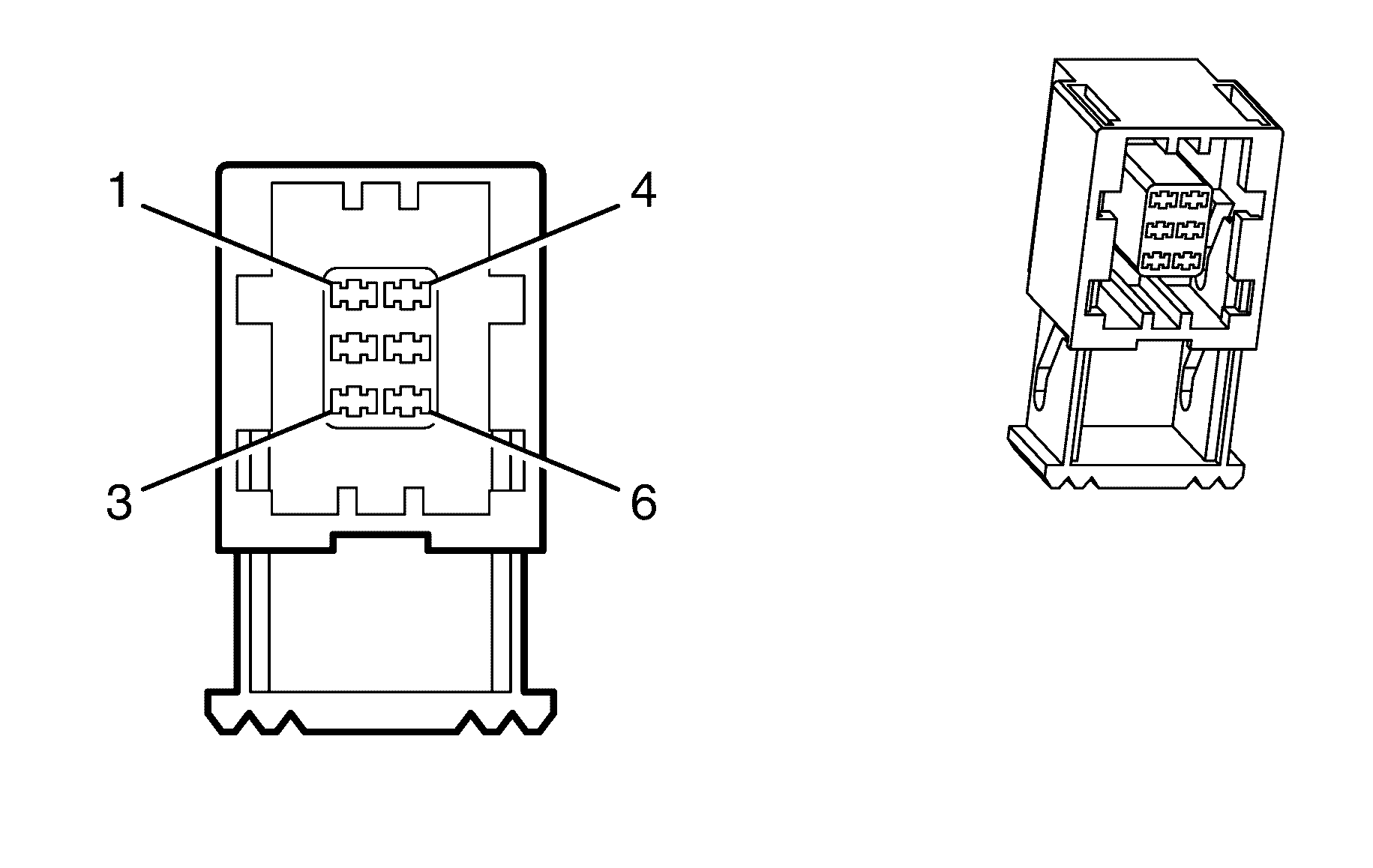
Connector Part Information
|
Terminal Part Information
|
Pin | Wire Color | Circuit No. | Function |
|---|---|---|---|
1 | -- | -- | Not Used |
2 | 0.75 BN/RD | 294 | Door Lock Actuator Unlock Control |
3 | 0.75 GN/WH | 295 | Door Lock Actuator Lock Control |
4 | 0.3 BN/WH | 746 | Passengers Door Ajar Switch Signal |
5 | -- | -- | Not Used |
6 | 0.5 BK | 2050 | Ground |
Door Latch - Passenger

Connector Part Information
|
Terminal Part Information
|
Pin | Wire Color | Circuit No. | Function |
|---|---|---|---|
1 | 0.3 GY/BK | 745 | Passengers Door Ajar Switch Signal |
2 | -- | -- | Not Used |
3 | 0.5 BK | 1350 | Ground |
4 | 0.3 PK | 781 | Driver Door Lock Switch Unlock Signal |
5-6 | -- | -- | Not Used |
7 | 0.75 BN/RD | 694 | Driver Door Lock Actuator Unlock Control |
8 | 0.75 GN/WH | 295 | Door Lock Actuator Lock Control |
9 | 0.3 PK/BK | 780 | Driver Door Lock Switch Lock Signal |
10 | -- | -- | Not Used |
Door Latch - Right Rear

Connector Part Information
|
Terminal Part Information
|
Pin | Wire Color | Circuit No. | Function |
|---|---|---|---|
1 | 0.3 BN/WH | 746 | Passengers Door Ajar Switch Signal |
2 | -- | -- | Not Used |
3 | 0.5 BK | 1350 | Ground |
4 | -- | -- | Not Used |
5 | 0.75 BN/RD | 294 | Door Lock Actuator Unlock Control |
6 | 0.75 GN/WH | 295 | Door Lock Actuator Lock Control |
Door Lock/Window Switch X1
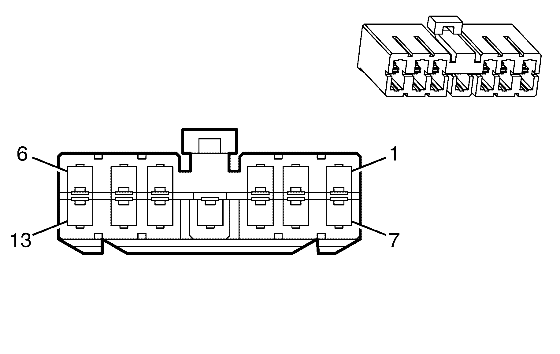
Connector Part Information
|
Terminal Part Information
|
Pin | Wire Color | Circuit No. | Function |
|---|---|---|---|
1-6 | -- | -- | Not Used |
7 | 2 PU | 169 | Power Window Master Switch Left Rear Down Signal |
8 | 2 D-GN | 168 | Power Window Master Switch Left Rear Up Signal |
9 | 2 BK | 2050 | Ground |
10 | 2 D-GN | 1001 | RAP [X] Fuse Supply Voltage |
11 | 2 D-BU | 1307 | Power Window Master Switch Lockout Signal |
12 | 2 PU/WH | 171 | Power Window Master Switch Right Rear Down Signal |
13 | 2 L-GN | 170 | Power Window Master Switch Right Rear Up Signal |
Door Lock/Window Switch X2
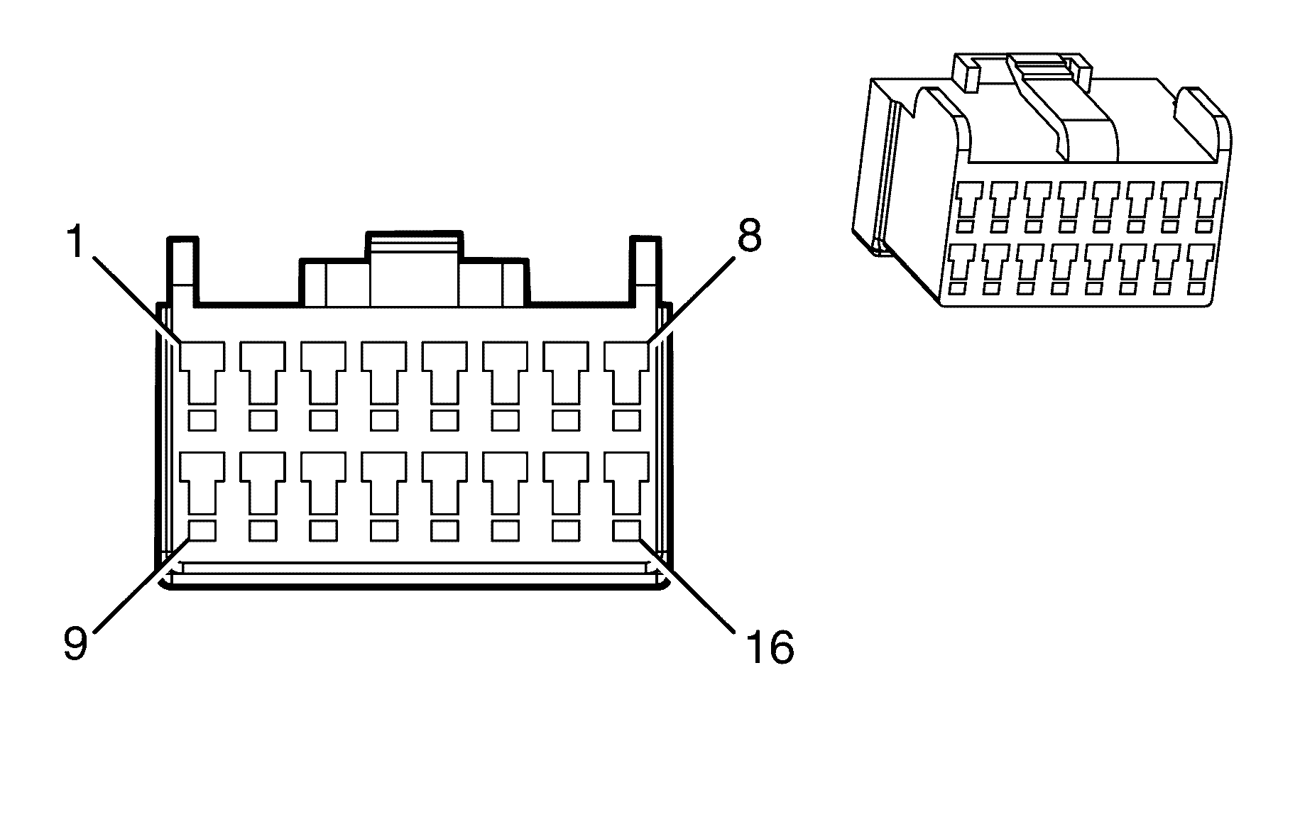
Connector Part Information
|
Terminal Part Information
|
Pin | Wire Color | Circuit No. | Function |
|---|---|---|---|
1 | 0.5 D-GN | 1301 | RAP [X] Fuse Supply Voltage |
2 | 0.5 BN | 1300 | Power Window Master Switch Left Front Up Signal |
3 | 0.5 GY/BU | 1136 | Power Window Master Switch Left Front Down Signal |
4 | 0.5 BK | 2050 | Ground |
5 | 0.5 BN/BK | 254 | Power Door Unlock Fuse Supply Voltage |
6 | 0.5 WH/BK | 81 | Driver Mirror Motor Right Control |
7 | 0.5 L-GN/BK | 89 | Driver Mirror Motor Down Control |
8 | 0.5 WH/BU | 7391 | Power Window Switch Right and Up |
9 | 0.5 L-BU | 166 | Power Window Master Switch Right Front Up Signal |
10 | 0.5 GN/BK | 167 | Power Window Master Switch Right Front Down Signal |
11 | 0.3 YE | 6817 | LED Backlight Diming Control |
12 | 0.5 PU/WH | 889 | Passenger Mirror Motor Down Control |
13 | 0.5 OG/WH | 881 | Passenger Mirror Motor Right Control |
14 | 0.5 BK | 2050 | Ground |
15 | 0.3 GY/BK | 255 | Power Door Lock Fuse Supply Voltage |
16 | 0.5 BN/BU | 343 | Accessory Voltage |
Driver Information Center (DIC) Display
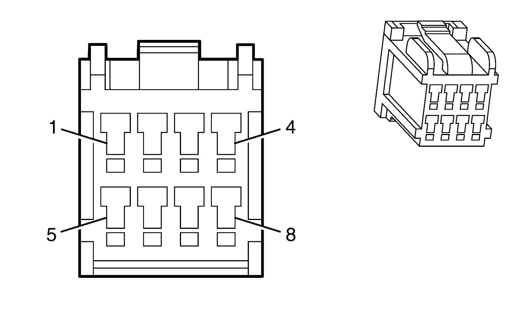
|
Terminal Part Information
|
Pin | Wire Color | Circuit No. | Function |
|---|---|---|---|
1 | 0.35 D-GN | 5060 | Low Speed GMLAN Serial Data |
2-3 | -- | -- | Not Used |
4 | 0.5 RD/WH | 1840 | Battery Positive Voltage |
5-7 | -- | -- | Not Used |
8 | 0.3 BK | 1450 | Ground |
Electronic Brake Control Module (EBCM)
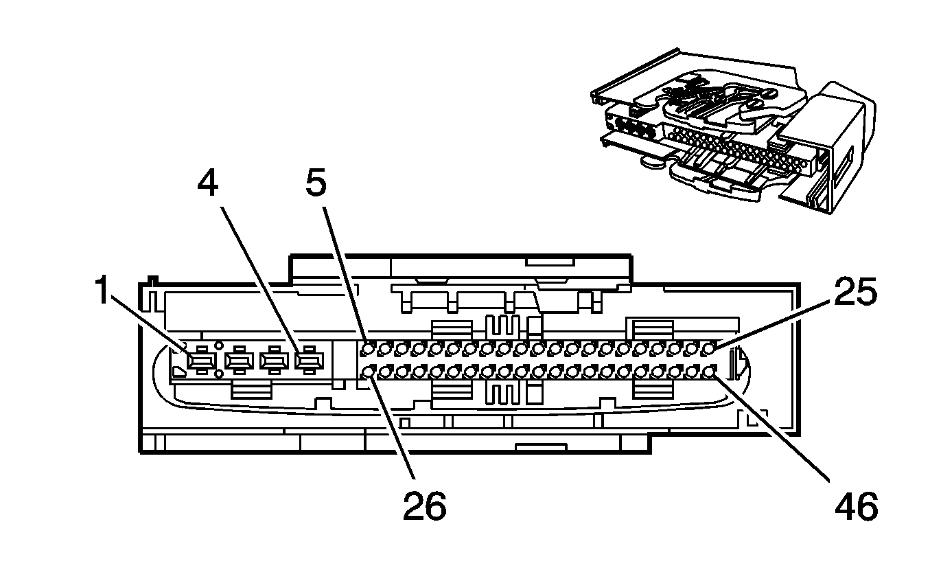
Connector Part Information
|
Terminal Part Information
|
Pin | Wire Color | Circuit No. | Function |
|---|---|---|---|
1 | 3 BK | 350 | Ground |
2 | 3 RD/BK | 142 | Battery Positive Voltage |
3 | 2 OG | 3540 | Battery Positive Voltage |
4 | 2 BK | 350 | Ground |
5 | 0.5 L-BU | 830 | Left Front Wheel Speed Sensor Signal |
6 | 0.5 GY | 7127 | Wheel Speed Sensor Supply Voltage Left Rear |
7 | 0.5 GY | 7128 | Wheel Speed Sensor Supply Voltage Right Rear |
8 | 0.5 BN | 882 | Right Rear Wheel Speed Sensor Signal |
9 | 0.5 GY | 7065 | Wheel Speed Sensor Supply Voltage Right Front |
10 | 0.5 D-GN | 872 | Wheel Speed Sensor Signal Right Front |
11-13 | -- | -- | Not Used |
14 | 0.5 BN | 9003 | High Speed GMLAN Serial Data Bus- (LY7) |
0.5 BN | 9005 | High Speed GMLAN Serial Data Bus- (L76) | |
15 | 0.5 BK/BU | 2088 | Steering Wheel Position Sensor Low Reference |
16 | 0.5 BN/WH | 2086 | Yaw Rate Sensor Test Control |
17 | -- | -- | Not Used |
18 | 0.5 D-GN | 2087 | Steering Wheel Position Sensor 5-V Reference |
19 | -- | -- | Not Used |
20 | 0.5 PU/WH | 1699 | Combined Vehicle Inertial Sensor Signal |
21-24 | -- | -- | Not Used |
25 | 0.5 BN | 9001 | High Speed GMLAN Serial Data Bus- (LY7) |
0.5 BN | 9003 | High Speed GMLAN Serial Data Bus- (L76) | |
26 | 0.5 GY | 7064 | Wheel Speed Sensor Supply Voltage Left Front |
27 | 0.5 BN/BK | 884 | Left Rear Wheel Speed Sensor Signal |
28 | 0.75 L-BU | 5986 | Communication Enable Relay Supply Voltage |
29-34 | -- | -- | Not Used |
35 | 0.5 BN/BK | 9002 | High Speed GMLAN Serial Data Bus+ (LY7) |
0.5 BN/BK | 9004 | High Speed GMLAN Serial Data Bus+ (L76) | |
36 | -- | -- | Not Used |
37 | 0.5 L-GN/BK | 5352 | Yaw Rate Sensor Test Control |
38-44 | -- | -- | Not Used |
45 | 0.5 BN/BK | 9000 | High Speed GMLAN Serial Data Bus+ (LY7) |
0.5 BN/BK | 9002 | High Speed GMLAN Serial Data Bus+ (L76) | |
46 | -- | -- | Not Used |
Engine Control Module (ECM) (L76) X1
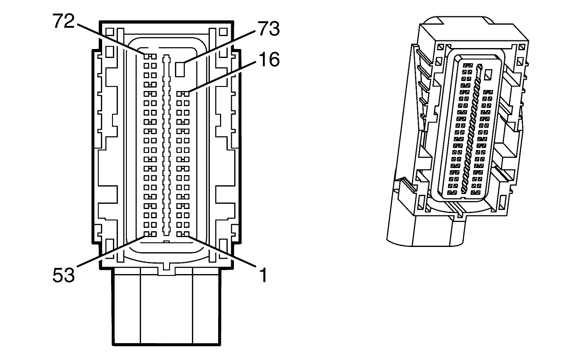
Connector Part Information
|
Terminal Part Information
|
Pin | Wire Color | Circuit No. | Function |
|---|---|---|---|
1 | 0.5 OG/BK | 1786 | Park/Neutral Signal |
2-8 | -- | -- | Not Used |
9 | 0.5 WH/BU | 17 | Stop Lamp Switch Signal |
10 | 0.5 PU/WH | 1668 | HO2S High Signal (Bank 1 Sensor 2) |
11 | 0.5 BN/WH | 1669 | HO2S Low Signal (Bank 1 Sensor 2) |
12 | 0.5 OG/BK | 380 | A/C Refrigerant Pressure Sensor Signal |
13 | 0.5 BN/GN | 2759 | Low Reference |
14-15 | -- | -- | Not Used |
16 | 0.5 PU | 1589 | Fuel Level Sensor Signal (Primary) |
17 | 0.5 D-BU/BK | 473 | High Speed Cooling Fan Relay Control |
18 | 0.5 D-BU | 5985 | Accessory Wakeup Serial Data |
19 | 0.5 PK | 439 | Ignition 1 Voltage |
20 | 0.75 OG/BK | 540 | Battery Positive Voltage |
21 | 0.5 D-BU | 1809 | Brake Booster Vacuum Sensor |
22 | 0.5 L-GN/BK | 6258 | 5V Return Brake Booster Vacuum |
23 | 0.5 PU | 1272 | Low Reference |
24 | 0.5 D-GN | 890 | Fuel Tank Vapour Pressure |
25-26 | -- | -- | Not Used |
27 | 0.5 BN | 9001 | High Speed GMLAN Serial Data Bus- |
28 | 0.5 BN/BK | 9000 | High Speed GMLAN Serial Data Bus+ |
29 | 0.5 D-BU/WH | 1161 | APP Sensor 1 Signal |
30 | 0.5 BN | 1271 | Low Reference |
31 | 0.5 BN/YE | 452 | Low Reference |
32 | 0.5 L-BU | 1162 | APP Sensor 2 Signal |
33 | 0.5 GY | 2709 | 5V reference |
34 | 0.5 GY | 1688 | 5-Volt Reference |
35 | -- | -- | Not Used |
36 | 0.5 BN/YE | 1274 | 5-Volt Reference |
37 | 0.5 BN/RD | 472 | IAT Sensor Signal |
38 | 0.5 BN/WH | 2760 | Low Reference |
39-40 | -- | -- | Not Used |
41 | 0.5 YE | 492 | MAF Sensor Signal |
42-46 | -- | -- | Not Used |
47 | 0.75 PK/BU | 5290 | Ignition 1 Voltage |
48 | -- | -- | Not Used |
49 | 0.5 BN/WH | 1671 | HO2S Low Signal (Bank 2 Sensor 2) |
50 | 0.5 D-GN/WH | 465 | Fuel Pump Relay Control (Primary) |
51 | -- | -- | Not Used |
52 | 0.5 YE | 447 | Starter Relay Coil Control |
53 | 0.5 L-GN | 6257 | 5V reference |
54-55 | -- | -- | Not Used |
56 | 0.5 WH/BK | 1164 | 5-Volt Reference |
57 | -- | -- | Not Used |
58 | 0.5 D-GN | 335 | Low Speed Cooling Fan Relay Control |
59 | 0.5 BN | 5069 | Main Relay Control |
60 | -- | -- | Not Used |
61 | 0.5 WH | 1310 | Fuel Tank Vent |
62-63 | -- | -- | Not Used |
64 | 0.5 OG/WH | 3223 | HO2S Heater Low Control (Bank 2 Sensor 2) |
65 | 0.5 BN | 2391 | HO2S Heater Low Control (Bank 1 Sensor 2) |
66-67 | -- | -- | Not Used |
68 | 0.5 BN/WH | 419 | MIL Control |
69 | 0.5 PU | 1670 | HO2S High Signal (Bank 2 Sensor 2) |
70 | 0.5 L-BU | 1937 | Fuel Level Sensor Signal (Secondary) |
71-72 | -- | -- | Not Used |
73 | 2 BK | 450 | Ground |
Engine Control Module (ECM) (L76) X2
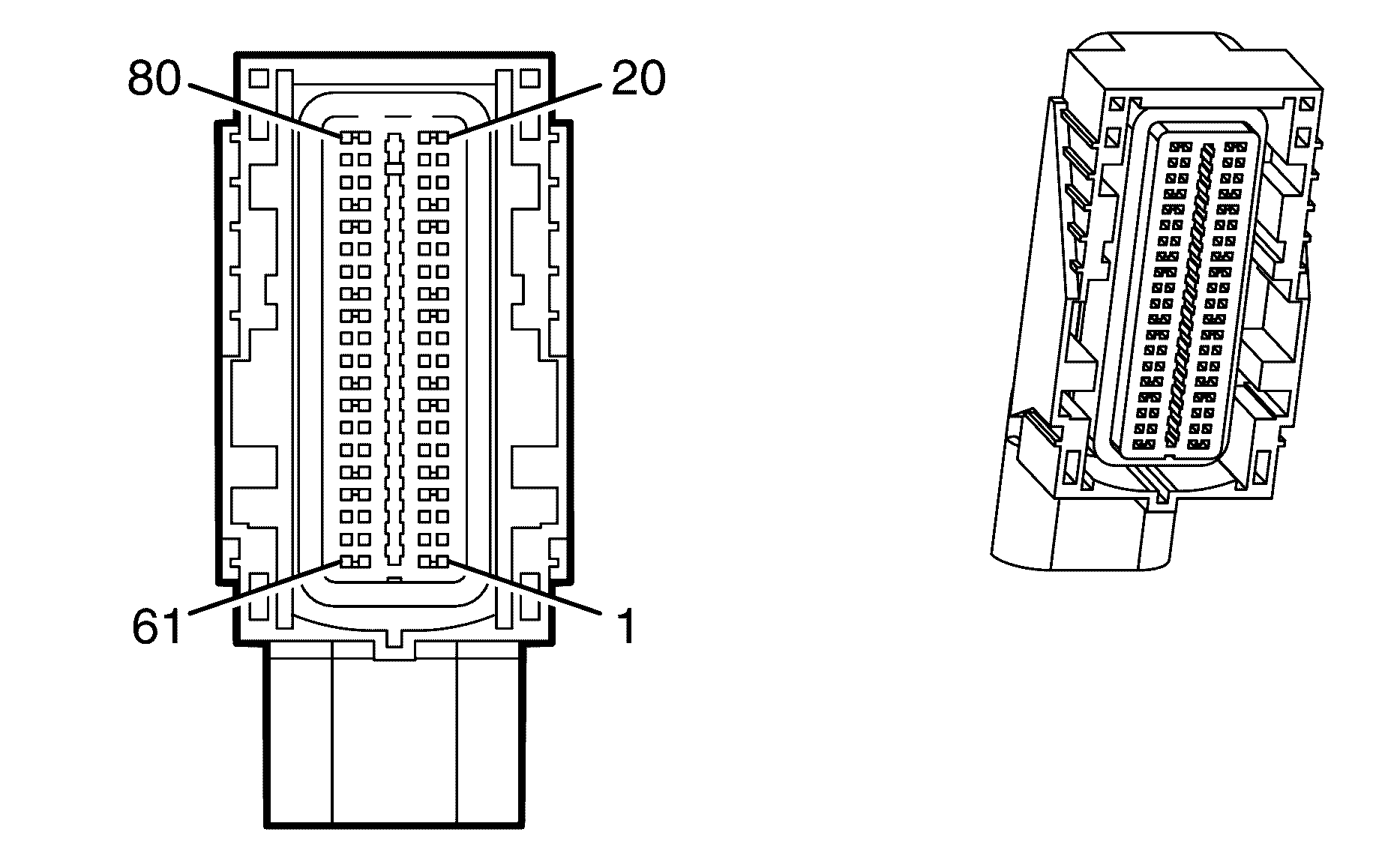
Connector Part Information
|
Terminal Part Information
|
Pin | Wire Color | Circuit No. | Function |
|---|---|---|---|
1 | -- | -- | Not Used |
2 | 0.5 L-GN | 1867 | 5-Volt Reference |
3 | 0.5 GY | 2701 | 5-Volt Reference |
4 | -- | -- | Not Used |
5 | 0.75 BN | 582 | TAC Motor Control - 2 |
6 | 0.75 YE | 581 | TAC Motor Control - 1 |
7 | -- | -- | Not Used |
8 | 0.75 D-GN/WH | 428 | EVAP Canister Purge Solenoid Control |
9 | 0.75 GY | 5493 | Cylinder Shut Off Solenoid 3 |
10 | 0.75 D-BU | 5491 | Cylinder Shut Off Solenoid 1 |
11 | 0.75 OG | 5494 | Cylinder Shut Off Solenoid 4 |
12 | 0.5 GY/WH | 3113 | HO2S Heater Low Control (Bank 1 Sensor 1) |
13 | 0.5 L-GN | 3212 | HO2S Heater Low Control (Bank 2 Sensor 1) |
14 | 0.75 D-GN/BK | 5492 | Cylinder Shut Off Solenoid 2 |
15-16 | -- | -- | Not Used |
17 | 0.75 D-BU/WH | 878 | Fuel Injector 8 Control |
18 | 0.75 BN/WH | 845 | Fuel Injector 5 Control |
19 | 0.75 YE/BK | 846 | Fuel Injector 6 Control |
20 | 0.75 BN/BK | 1744 | Fuel Injector 1 Control |
21 | 0.5 YE/GN | 410 | ECT Sensor Signal |
22 | 0.5 BN/WH | 2761 | Low Reference |
23 | 0.5 D-GN/YE | 357 | Oil Temperature Sensor Signal |
24 | 0.5 BN/RD | 470 | Low Reference |
25 | -- | -- | Not Used |
26 | 0.5 D-BU | 496 | Knock Sensor 1 Signal |
27 | 0.5 GY | 1716 | Low Reference Knock Sensor Signal Return |
28 | -- | -- | Not Used |
29 | 0.5 L-BU | 1876 | Knock Sensor 2 Signal |
30 | 0.5 BN | 407 | Low Reference |
31 | -- | -- | Not Used |
32 | 0.5 PU/WH | 23 | Generator Field Duty Cycle Signal |
33 | 0.5 BN | 1174 | Oil Level Switch Signal |
34 | 0.5 BK | 2755 | Low Reference |
35 | 0.5 BN/BK | 2752 | Low Reference |
36 | -- | -- | Not Used |
37 | 0.75 L-GN/BK | 1745 | Fuel Injector 2 Control |
38 | 0.75 PK/BK | 1746 | Fuel Injector 3 Control |
39 | 0.75 L-BU/BK | 844 | Fuel Injector 4 Control |
40 | 0.75 OG/BK | 877 | Fuel Injector 7 Control |
41 | 0.5 GY | 2705 | 5-Volt Reference |
42 | -- | -- | Not Used |
43 | 0.5 GY | 2704 | 5-Volt Reference |
44 | 0.5 OG | 631 | 5-Volt Reference |
45-49 | -- | -- | Not Used |
50 | 0.5 BN/WH | 331 | Oil Pressure Sensor Signal |
51-52 | -- | -- | Not Used |
53 | 0.5 OG/BK | 469 | Low Reference |
54-55 | -- | -- | Not Used |
56 | 0.5 BN/YE | 1664 | HO2S Low Signal (Bank 1 Sensor 1) |
57 | P0.5 U/WH | 1665 | HO2S High Signal (Bank 1 Sensor 1) |
58 | 0.5 L-GN | 432 | MAP Sensor Signal |
59 | 0.5 PU | 1666 | HO2S High Signal (Bank 2 Sensor 1) |
60 | 0.5 BN/RD | 1667 | HO2S Low Signal (Bank 2 Sensor 1) |
61 | 0.5 OG/WH | 225 | Generator Turn On Signal |
62 | -- | -- | Not Used |
63 | 0.5 PU | 486 | TP Sensor 2 Signal |
64 | 0.5 BN/WH | 633 | CMP Sensor Signal |
65 | 0.5 D-GN | 485 | TP Sensor 1 Signal |
66 | 0.5 PK/BK | 632 | Low Reference |
67 | -- | -- | Not Used |
68 | 0.5 D-BU/WH | 1869 | CKP Sensor Signal |
69 | 0.5 YE/BK | 1868 | Low Reference |
70 | 0.5 PU | 2121 | IC 1 Control |
71 | 0.5 PU/WH | 2128 | IC 8 Control |
72 | 0.5 OG | 2127 | IC 7 Control |
73 | 0.5 OG/WH | 2122 | IC 2 Control |
74 | 0.5 L-BU/WH | 2126 | IC 6 Control |
75 | 0.5 D-GN/RD | 2125 | IC 5 Control |
76 | 0.5 D-GN/WH | 2124 | IC 4 Control |
77 | 0.5 L-BU | 2123 | IC 3 Control |
78 | 0.5 BN | 2129 | Low Reference |
79 | 0.5 BN/WH | 2130 | Low Reference |
80 | -- | -- | Not Used |
Engine Control Module (ECM) (LY7) X1
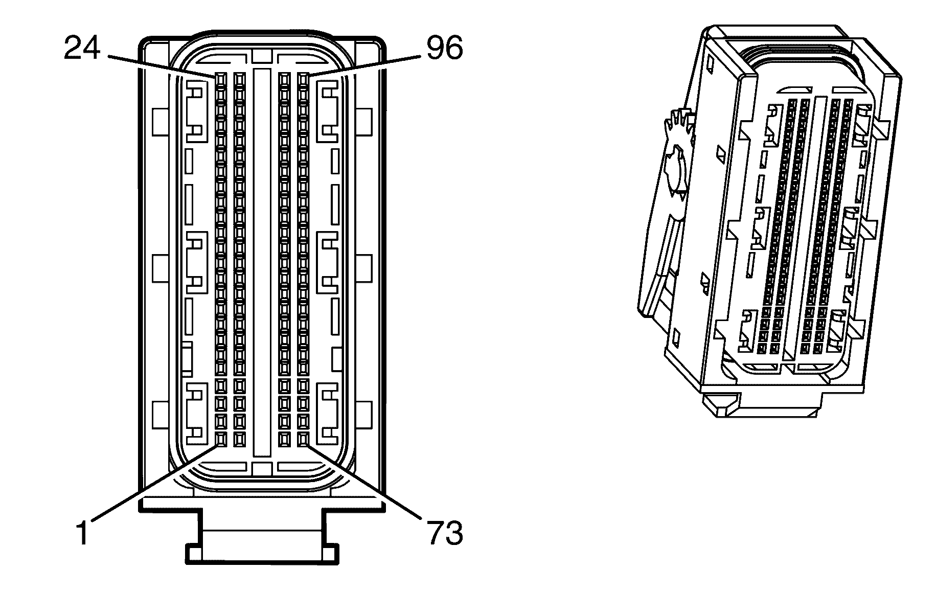
Connector Part Information
|
Terminal Part Information
|
Pin | Wire Color | Circuit No. | Function |
|---|---|---|---|
1 | 0.75 L-GN | 5282 | Cam Phaser Exhaust 1 Signal |
2 | 0.75 PU | 5284 | Cam Phaser Intake 1 Signal |
3 | -- | -- | Not Used |
4 | 0.75 YE/BK | 846 | Fuel Injector 6 Control |
5 | 0.75 D-GN/WH | 428 | EVAP Canister Purge Solenoid Control |
6 | -- | -- | Not Used |
7 | 0.5 OG/BU | 5275 | Intake 1 Cam Position Sensor Signal |
8 | -- | -- | Not Used |
9 | 0.5 PU | 5274 | Exhaust 2 Cam Position Sensor Signal |
10 | 0.5 OG/WH | 225 | Generator Turn On Signal |
11 | 0.5 BN | 1174 | Oil Level Switch Signal |
12 | -- | -- | Not Used |
13 | 0.5 PK | 6414 | Low Reference |
14 | 0.75 BN | 1997 | EVAP Canister Vent Solenoid Valve Low Reference |
15 | 0.75 GY | 705 | 5-Volt Reference |
16-23 | -- | -- | Not Used |
24 | 0.75 YE | 581 | TAC Motor Control - 1 |
25 | 0.75 WH/BK | 5283 | Cam Phaser Exhaust 2 Signal |
26 | 0.75 PK/BK | 1746 | Fuel Injector 3 Control |
27 | -- | -- | Not Used |
28 | 0.75 BN/WH | 845 | Fuel Injector 5 Control |
29 | -- | -- | Not Used |
30 | 0.5 PU/WH | 23 | Generator Field Duty Cycle Signal |
31-32 | -- | -- | Not Used |
33 | 0.5 YE/RD | 5276 | Intake 2 Cam Position Sensor Signal |
34 | 0.5 D-GN | 5273 | Exhaust 1 Cam Position Sensor Signal |
35 | 0.5 YE/BU | 573 | CKP Sensor 1 Signal |
36-38 | -- | -- | Not Used |
39 | 0.5 GY | 2701 | 5-Volt Reference |
40 | 0.5 GY | 596 | 5-Volt Reference |
41 | 0.75 PK/BK | 632 | Low Reference |
42 | -- | -- | Not Used |
43 | 0.5 BN/RD | 470 | Low Reference |
44 | 0.5 BK | 2755 | Low Reference |
45 | 0.5 PU/WH | 605 | 5-Volt Reference |
46 | 0.5 PU | 574 | Low Reference |
47 | -- | -- | Not Used |
48 | 0.75 BN | 582 | TAC Motor Control - 2 |
49 | 0.75 OG/BK | 5272 | Cam Phaser Intake 2 Signal |
50 | 0.75 L-BU/BK | 844 | Fuel Injector 4 Control |
51 | 0.75 BN/BK | 1744 | Fuel Injector 1 Control |
52 | 0.75 L-GN/BK | 1745 | Fuel Injector 2 Control |
53-54 | -- | -- | Not Used |
55 | 0.5 PU | 2121 | IC 1 Control |
56 | 0.5 L-BU | 2123 | IC 3 Control |
57 | 0.5 D-GN/RD | 2125 | IC 5 Control |
58 | -- | -- | Not Used |
59 | 0.5 D-BU | 496 | Knock Sensor 1 Signal |
60 | 0.5 BN | 407 | Low Reference |
61 | 0.5 BN/WH | 331 | Oil Pressure Sensor Signal |
62-66 | -- | -- | Not Used |
67 | 0.5 BN/YE | 1664 | HO2S Low Signal (Bank 1 Sensor 1) |
68-69 | -- | -- | Not Used |
70 | 0.5 PU | 1666 | HO2S High Signal (Bank 2 Sensor 1) |
71 | -- | -- | Not Used |
72 | 0.75 L-GN | 3212 | HO2S Low Signal (Bank 2 Sensor 1) |
73-77 | -- | -- | Not Used |
78 | 0.5 PU | 6413 | Low Reference |
79 | 0.5 OG/WH | 2122 | IC 2 Control |
80 | 0.5 D-GN/WH | 2124 | IC 4 Control |
81 | 0.5 L-BU/WH | 2126 | IC 6 Control |
82 | 0.5 YE/GN | 410 | ECT Sensor Signal |
83 | 0.5 GY | 1716 | Low Reference |
84 | 0.5 L-BU | 1876 | Knock Sensor 2 Signal |
85 | 0.5 D-GN/YE | 357 | Oil Temperature Sensor Signal |
86-87 | -- | -- | Not Used |
88 | 0.5 BN/BK | 2752 | Low Reference |
89 | 0.5 PU | 486 | TP Sensor 2 Signal |
90 | 0.5 D-GN | 485 | TP Sensor 1 Signal |
91 | -- | -- | Not Used |
92 | 0.5 PU/WH | 1665 | HO2S High Signal (Bank 1 Sensor 1) |
93 | 0.5 BN/RD | 1667 | HO2S Low Signal (Bank 2 Sensor 1) |
94-95 | -- | -- | Not Used |
96 | 0.75 GY/WH | 3113 | HO2S Heater Low Control (Bank 1 Sensor 1) |
Engine Control Module (ECM) (LY7) X2
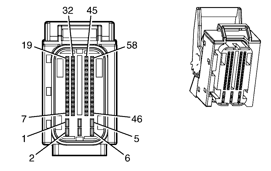
Connector Part Information
|
Terminal Part Information
|
Pin | Wire Color | Circuit No. | Function |
|---|---|---|---|
1 | 0.5 BK | 450 | Ground |
2 | 0.5 BK | 450 | Ground |
3 | 0.75 PK/BU | 5290 | Ignition 1 Voltage |
4 | 0.5 BK | 450 | Ground |
5 | 0.75 PK/BU | 5290 | Ignition 1 Voltage |
6 | 0.75 PK/BU | 5290 | Ignition 1 Voltage |
7 | 0.75 GY/WH | 3122 | HO2S Heater Low Control (Bank 1 Sensor 2) |
8 | -- | -- | Not Used |
9 | 0.5 BN/YE | 452 | Low Reference |
10 | 0.5 D-GN/WH | 465 | Fuel Pump Relay Control (Primary) |
11 | 0.5 BN/GN | 2759 | Low Reference |
12 | -- | -- | Not Used |
13 | 0.5 YE | 492 | MAF Sensor Signal |
14 | 0.5 OG/BU | 9709 | 5-Volt Reference |
15 | 0.5 D-BU/WH | 1161 | APP Sensor 1 Signal |
16 | -- | -- | Not Used |
17 | 0.5 OG/BK | 1786 | Park/Neutral Signal |
18 | -- | -- | Not Used |
19 | 0.5 WH | 1310 | Fuel System Cannister Vent |
20 | 0.75 OG/WH | 3223 | HO2S Heater Low Control (Bank 2 Sensor 2) |
21 | 0.5 BN/WH | 419 | MIL Control |
22 | 0.5 BN/WH | 2760 | Low Reference |
23 | 0.5 BN/GN | 3121 | HO2S Low Signal (Bank 1 Sensor 2) |
24 | 0.5 BN/RD | 3221 | HO2S Low Signal (Bank 2 Sensor 2) |
25 | 0.5 L-BU | 1162 | APP Sensor 2 Signal |
26 | 0.5 L-BU | 1937 | Fuel Level Sensor Signal (1) |
27 | 0.5 D-GN | 890 | Fuel Pressure Signal |
28-33 | -- | -- | Not Used |
34 | 0.5 BN | 1271 | Low Reference |
35 | 0.5 GY | 2709 | 5-Volt Reference |
36 | 0.5 PU | 1589 | Fuel Level Sensor Signal (2) |
37 | -- | -- | Not Used |
38 | 0.5 PU | 3120 | HO2S High Signal (Bank 1 Sensor 2) |
39 | 0.5 OG/BK | 380 | A/C Refrigerant Pressure Sensor Signal |
40 | -- | -- | Not Used |
41 | 0.5 D-BU | 5985 | Accessory Wakeup Serial Data |
42 | 0.5 BN/BK | 9000 | High Speed GMLAN Serial Data Bus+ |
43-44 | -- | -- | Not Used |
45 | 0.5 D-BU/BK | 473 | High Speed Cooling Fan Relay Control |
46 | 0.5 D-GN | 335 | Low Speed Cooling Fan Relay Control |
47 | 0.5 PU | 1272 | Low Reference |
48 | 0.5 BN/YE | 1274 | 5-Volt Reference |
49 | 0.5 WH/BK | 1164 | 5-Volt Reference |
50 | 0.5 BN/RD | 472 | IAT Sensor Signal |
51 | 0.5 PU | 3220 | HO2S High Signal (Bank 2 Sensor 2) |
52 | 0.5 WH/BU | 17 | Stop Lamp Switch Signal |
53 | -- | -- | Not Used |
54 | 0.5 PK | 439 | Ignition 1 Voltage |
55 | 0.5 BN | 9001 | High Speed GMLAN Serial Data Bus- |
56 | O0.75 G/BK | 540 | Battery Positive Voltage |
57 | 0.5 YE | 447 | Starter Relay Coil Control |
58 | 0.5 BN | 5069 | Main Relay Control |
Engine Coolant Temperature (ECT) Sensor (L76)
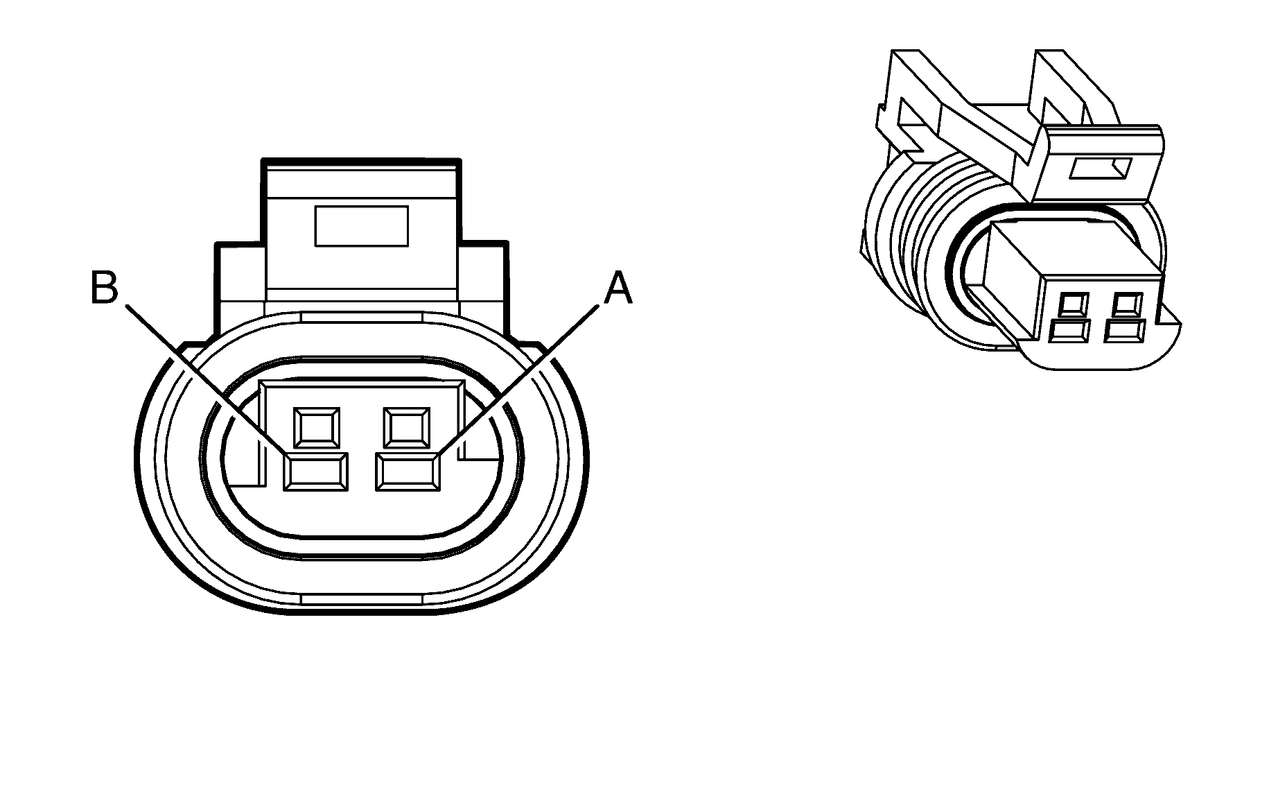
Connector Part Information
|
Terminal Part Information
|
Pin | Wire Color | Circuit No. | Function |
|---|---|---|---|
A | 0.5 BN/WH | 2761 | Low Reference |
B | 0.5 YE/GN | 410 | ECT Sensor Signal |
Engine Coolant Temperature (ECT) Sensor (LY7)
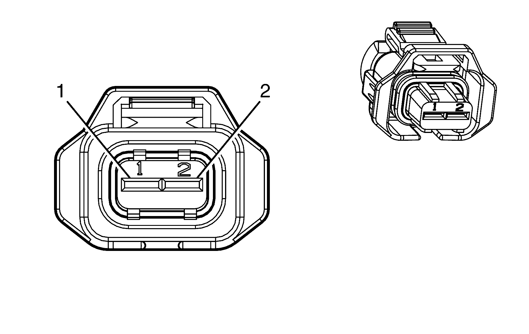
Connector Part Information
|
Terminal Part Information
|
Pin | Wire Color | Circuit No. | Function |
|---|---|---|---|
1 | 0.5 YE/GN | 410 | ECT Sensor Signal |
2 | 0.5 BK | 2755 | Low Reference |
Engine Cooling Fan - Left
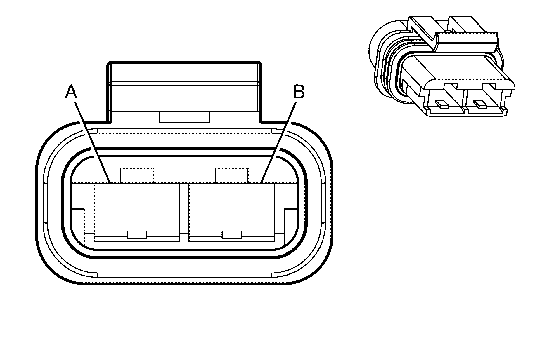
Connector Part Information
|
Terminal Part Information
|
Pin | Wire Color | Circuit No. | Function |
|---|---|---|---|
A | 3 BK | 250 | Ground |
B | 3 D-BU | 409 | Left Cooling Fan Motor Supply Voltage |
Engine Cooling Fan - Right

Connector Part Information
|
Terminal Part Information
|
Pin | Wire Color | Circuit No. | Function |
|---|---|---|---|
A | 3 GY | 532 | Right Cooling Fan Motor Low Reference |
B | 3 WH | 504 | Right Cooling Fan Motor Supply Voltage |
Engine Oil Level and Temperature Sensor

Connector Part Information
|
Terminal Part Information
|
Pin | Wire Color | Circuit No. | Function |
|---|---|---|---|
A | 0.5 BN | 1174 | Oil Level Switch Signal |
B | 0.5 L-GN/YE | 357 | Oil Temperature Sensor Signal |
C | 0.5 BN/RD | 470 | Low Reference (L76) |
0.5 BK | 2755 | Low Reference (LY7) |
Engine Oil Pressure (EOP) Sensor
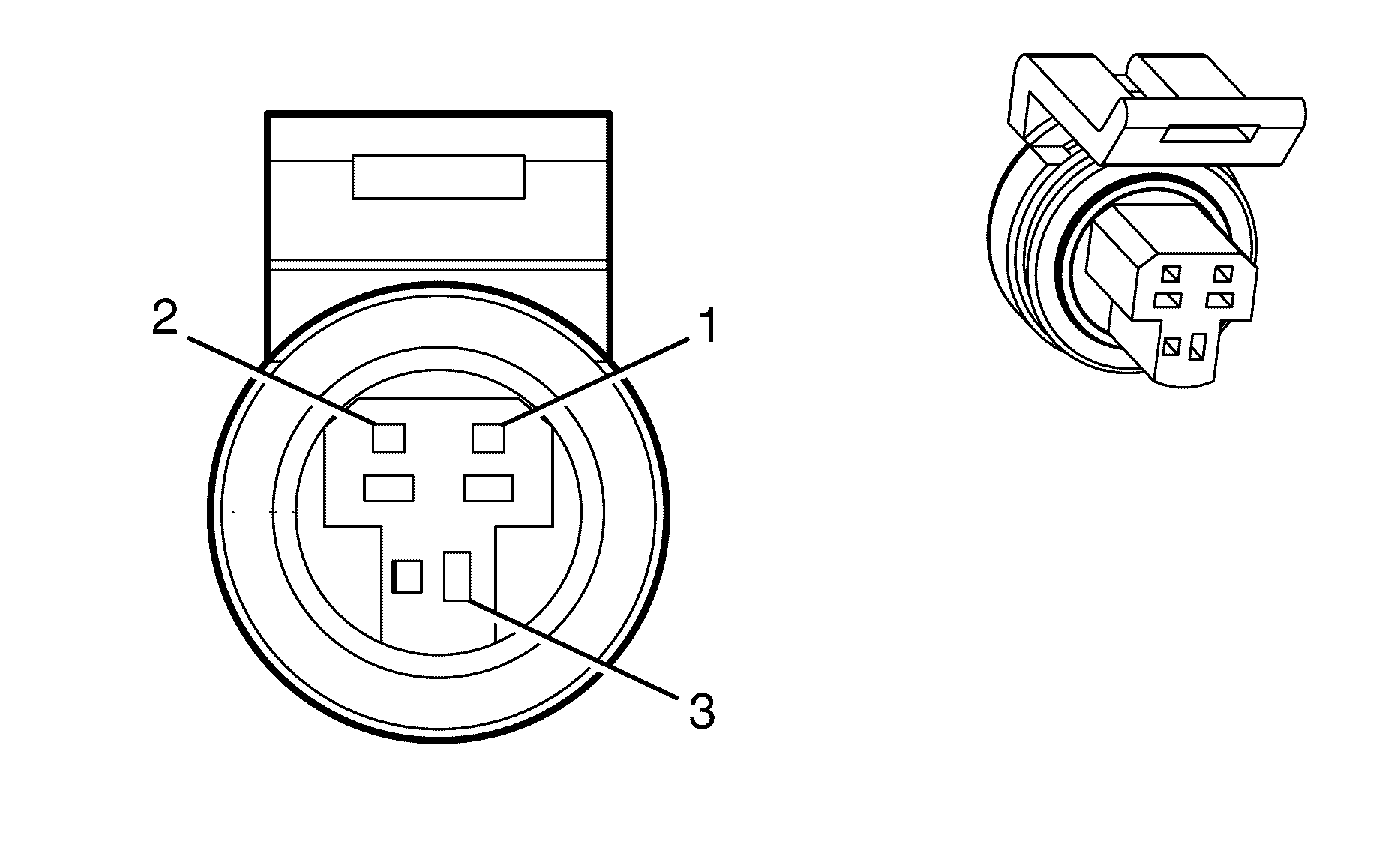
Connector Part Information
|
Terminal Part Information
|
Pin | Wire Color | Circuit No. | Function |
|---|---|---|---|
1 | 0.5 BK | 2755 | Low Reference (L76) |
0.5 BN/RD | 470 | Low Reference (LY7) | |
2 | 0.5 GY | 2705 | 5-Volt Reference (L76) |
0.5 GY | 596 | 5-Volt Reference (LY7) | |
3 | 0.5 BN/WH | 331 | Oil Pressure Sensor Signal (L76) |
0.5 BN/WH | 331 | Oil Pressure Sensor Signal (LY7) |
Evaporative Emission (EVAP) Canister Purge Solenoid Valve (L76)
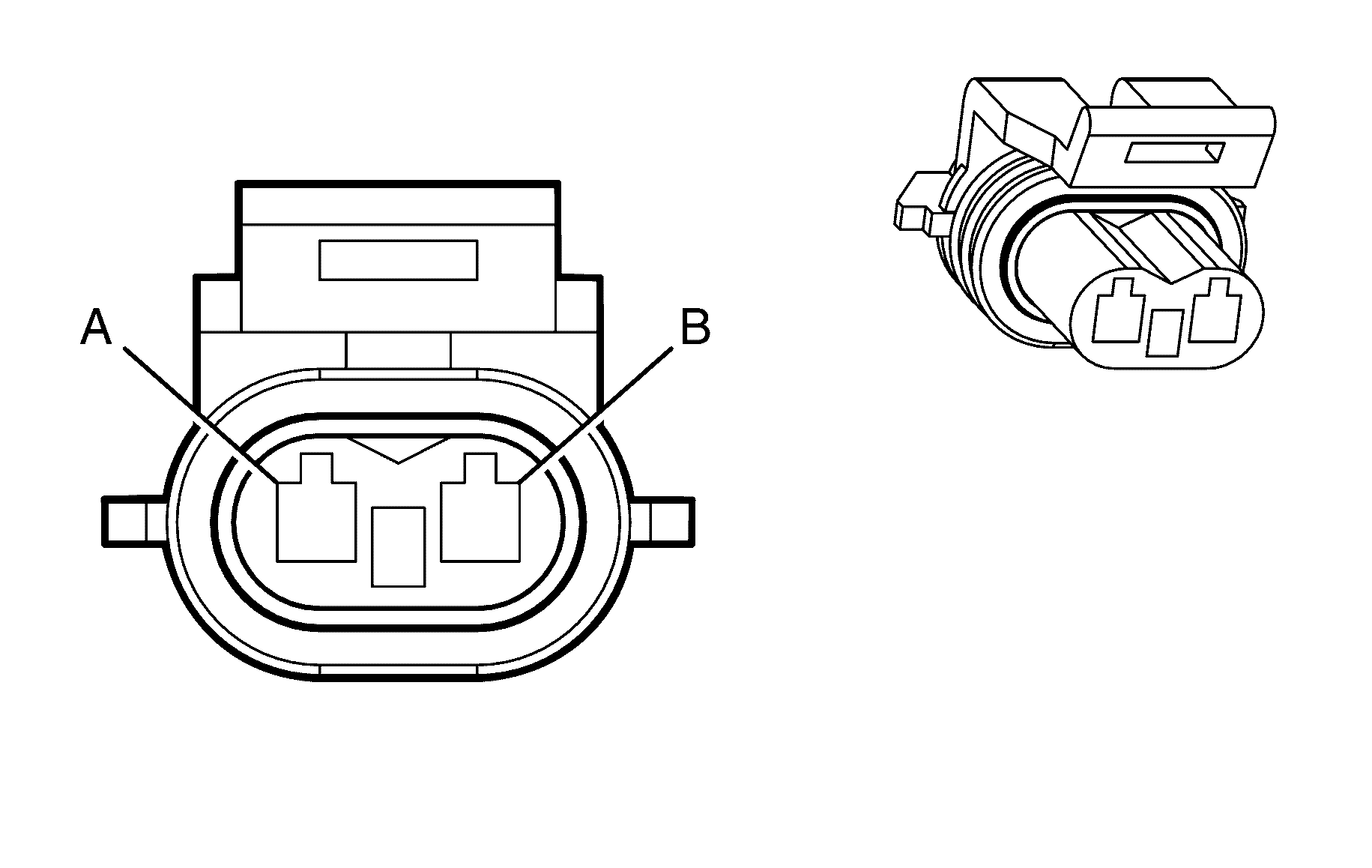
Connector Part Information
|
Terminal Part Information
|
Pin | Wire Color | Circuit No. | Function |
|---|---|---|---|
A | 0.75 PK/BU | 5293 | Ignition 1 Voltage |
B | 0.75 D-GN/WH | 428 | EVAP Canister Purge Solenoid Control |
Evaporative Emission (EVAP) Canister Purge Solenoid Valve (LY7)
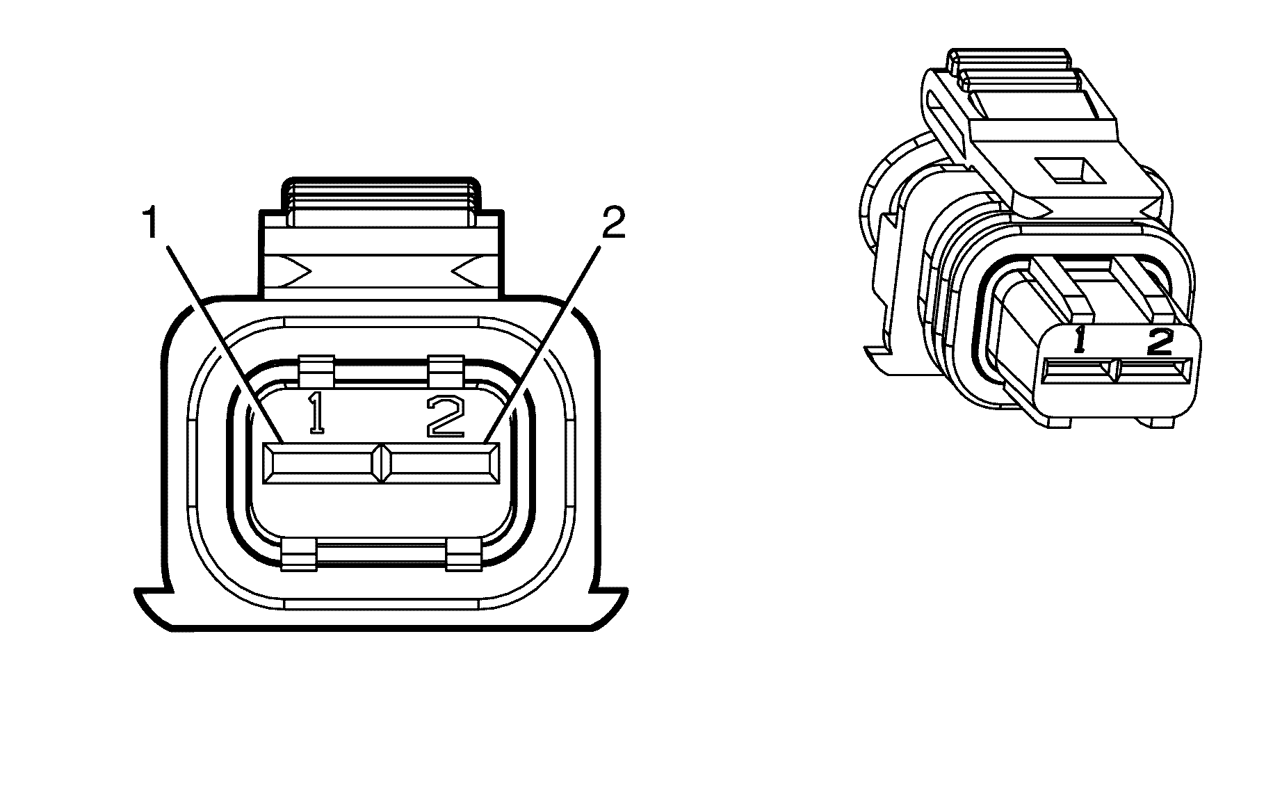
Connector Part Information
|
Terminal Part Information
|
Pin | Wire Color | Circuit No. | Function |
|---|---|---|---|
1 | 0.75 PK/BU | 5293 | Ignition 1 Voltage |
2 | 0.75 D-GN/WH | 428 | EVAP Canister Purge Solenoid Control |
Evaporative Emission (EVAP) Canister Vent Solenoid Valve

Connector Part Information
|
Terminal Part Information
|
Pin | Wire Color | Circuit No. | Function |
|---|---|---|---|
A | 0.5 OG | 3140 | Battery Positive Voltage |
B | 0.5 WH | 1310 | EVAP Canister Vent Solenoid Control |
Fog Lamp - Left Front
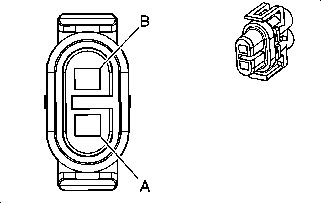
Connector Part Information
|
Terminal Part Information
|
Pin | Wire Color | Circuit No. | Function |
|---|---|---|---|
A | 0.75 PU | 34 | Fog Lamps Supply Voltage |
B | 0.75 BK | 350 | Ground |
Fog Lamp - Right Front

Connector Part Information
|
Terminal Part Information
|
Pin | Wire Color | Circuit No. | Function |
|---|---|---|---|
A | 0.75 PU | 34 | Fog Lamps Supply Voltage |
B | 0.75 BK | 350 | Ground |
Fuel Door Release Actuator
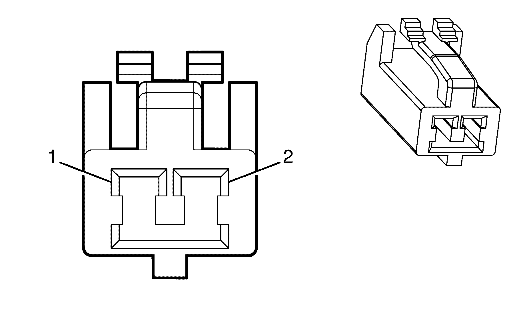
Connector Part Information
|
Terminal Part Information
|
Pin | Wire Color | Circuit No. | Function |
|---|---|---|---|
1 | 1.25 D-GN/WH | 295 | Door Lock Actuator Lock Control |
2 | 1.25 BN/RD | 694 | Driver Door Lock Actuator Unlock Control |
Fuel Injector 1 (LY7)
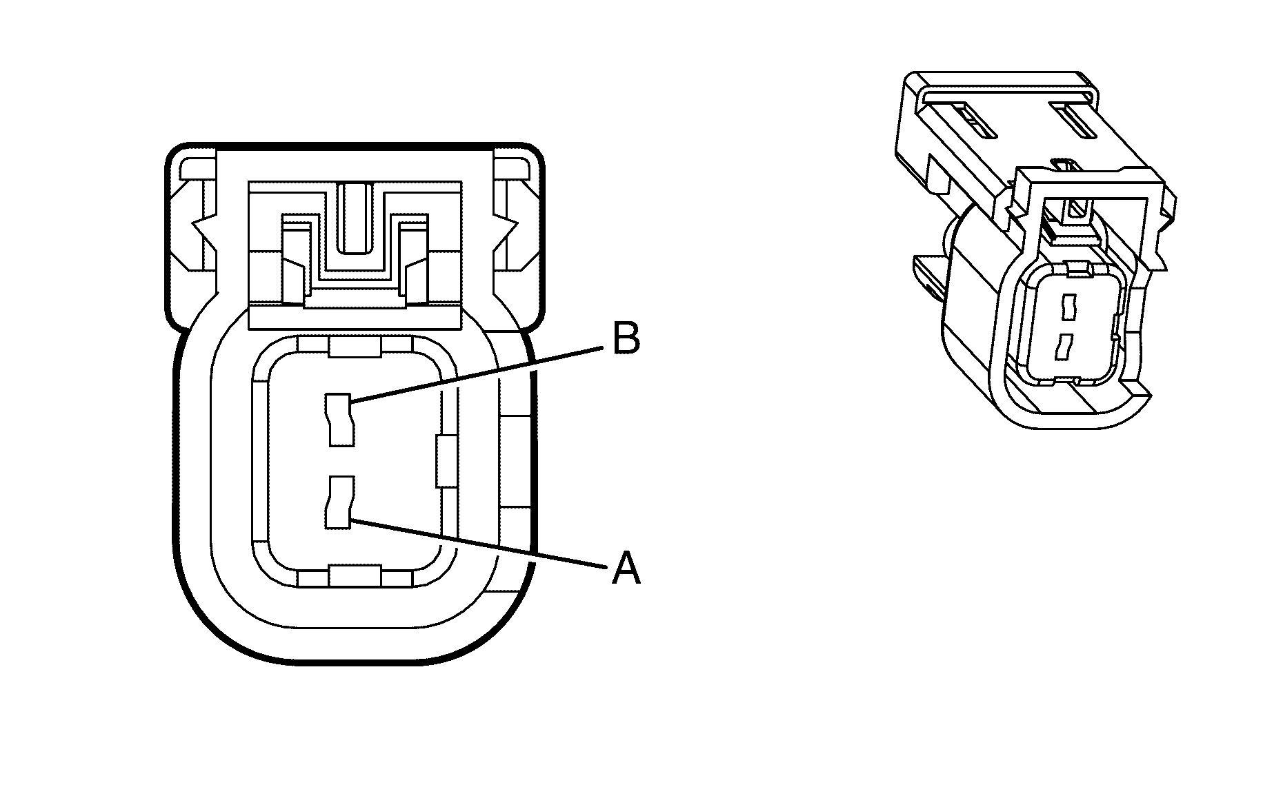
Connector Part Information
|
Terminal Part Information
|
Pin | Wire Color | Circuit No. | Function |
|---|---|---|---|
A | 0.8 WH | 5291 | Ignition 1 Voltage |
B | 0.5 TN | 1744 | Fuel Injector 1 Control |
Fuel Injector 1 (L76)

Connector Part Information
|
Terminal Part Information
|
Pin | Wire Color | Circuit No. | Function |
|---|---|---|---|
A | 0.75 PK/BU | 5291 | Ignition 1 Voltage |
B | 0.75 BN/BK | 1744 | Fuel Injector 1 Control |
Fuel Injector 2 (LY7)

Connector Part Information
|
Terminal Part Information
|
Pin | Wire Color | Circuit No. | Function |
|---|---|---|---|
A | 0.8 WH | 5292 | Ignition 1 Voltage |
B | 0.8 L-GN/BK | 1745 | Fuel Injector 2 Control |
Fuel Injector 2 (L76)

Connector Part Information
|
Terminal Part Information
|
Pin | Wire Color | Circuit No. | Function |
|---|---|---|---|
A | 0.75 PK | 5292 | Ignition 1 Voltage |
B | 0.75 L-GN/BK | 1745 | Fuel Injector 2 Control |
Fuel Injector 3 (LY7)

Connector Part Information
|
Terminal Part Information
|
Pin | Wire Color | Circuit No. | Function |
|---|---|---|---|
A | 0.8 WH | 5291 | Ignition 1 Voltage |
B | 0.8 PK/BK | 1746 | Fuel Injector 3 Control |
Fuel Injector 3 (L76)

Connector Part Information
|
Terminal Part Information
|
Pin | Wire Color | Circuit No. | Function |
|---|---|---|---|
A | 0.75 PK/BU | 5291 | Ignition 1 Voltage |
B | 0.75 PK/BK | 1746 | Fuel Injector 3 Control |
Fuel Injector 4 (LY7)

Connector Part Information
|
Terminal Part Information
|
Pin | Wire Color | Circuit No. | Function |
|---|---|---|---|
A | 0.8 WH | 5292 | Ignition 1 Voltage |
B | 0.8 L-BU/BK | 844 | Fuel Injector 4 Control |
Fuel Injector 4 (L76)

Connector Part Information
|
Terminal Part Information
|
Pin | Wire Color | Circuit No. | Function |
|---|---|---|---|
A | 0.75 PK | 5292 | Ignition 1 Voltage |
B | 0.75 L-BU/BK | 844 | Fuel Injector 4 Control |
Fuel Injector 5 (LY7)

Connector Part Information
|
Terminal Part Information
|
Pin | Wire Color | Circuit No. | Function |
|---|---|---|---|
A | 0.8 WH | 5291 | Ignition 1 Voltage |
B | 0.8 TN/WH | 845 | Fuel Injector 5 Control |
Fuel Injector 5 (L76)

Connector Part Information
|
Terminal Part Information
|
Pin | Wire Color | Circuit No. | Function |
|---|---|---|---|
A | 0.75 PK/BU | 5291 | Ignition 1 Voltage |
B | 0.75 BN/WH | 845 | Fuel Injector 5 Control |
Fuel Injector 6 (LY7)

Connector Part Information
|
Terminal Part Information
|
Pin | Wire Color | Circuit No. | Function |
|---|---|---|---|
A | 0.8 WH | 5292 | Ignition 1 Voltage |
B | 0.8 YE/BK | 846 | Fuel Injector 6 Control |
Fuel Injector 6 (L76)

Connector Part Information
|
Terminal Part Information
|
Pin | Wire Color | Circuit No. | Function |
|---|---|---|---|
A | 0.75 PK | 5292 | Ignition 1 Voltage |
B | 0.75 YE/BK | 846 | Fuel Injector 6 Control |
Fuel Injector 7 (L76)

Connector Part Information
|
Terminal Part Information
|
Pin | Wire Color | Circuit No. | Function |
|---|---|---|---|
A | 0.75 PK/BU | 5291 | Ignition 1 Voltage |
B | 0.75 OG/BK | 877 | Fuel Injector 7 Control |
Fuel Injector 8 (L76)

Connector Part Information
|
Terminal Part Information
|
Pin | Wire Color | Circuit No. | Function |
|---|---|---|---|
A | 0.75 PK | 5292 | Ignition 1 Voltage |
B | 0.75 D-BU/WH | 878 | Fuel Injector 8 Control |
Fuel Level Sensor - Secondary
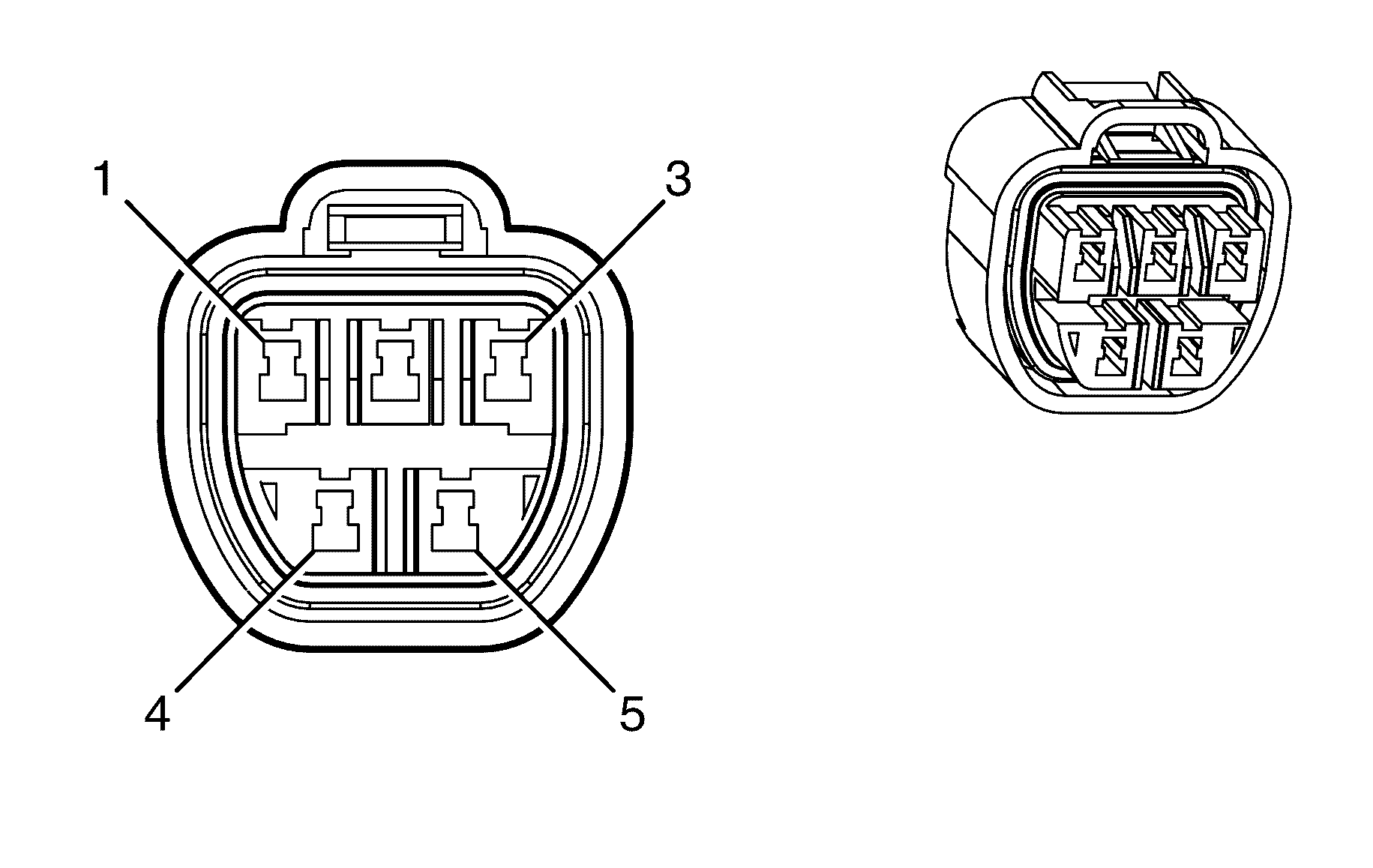
Connector Part Information
|
Terminal Part Information
|
Pin | Wire Color | Circuit No. | Function |
|---|---|---|---|
1 | 0.3 BN/YE | 452 | Fuel Return |
2 | 0.5 L-BU | 1937 | Fuel Level |
3-5 | -- | -- | Not Used |
Fuel Pump and Sender Assembly
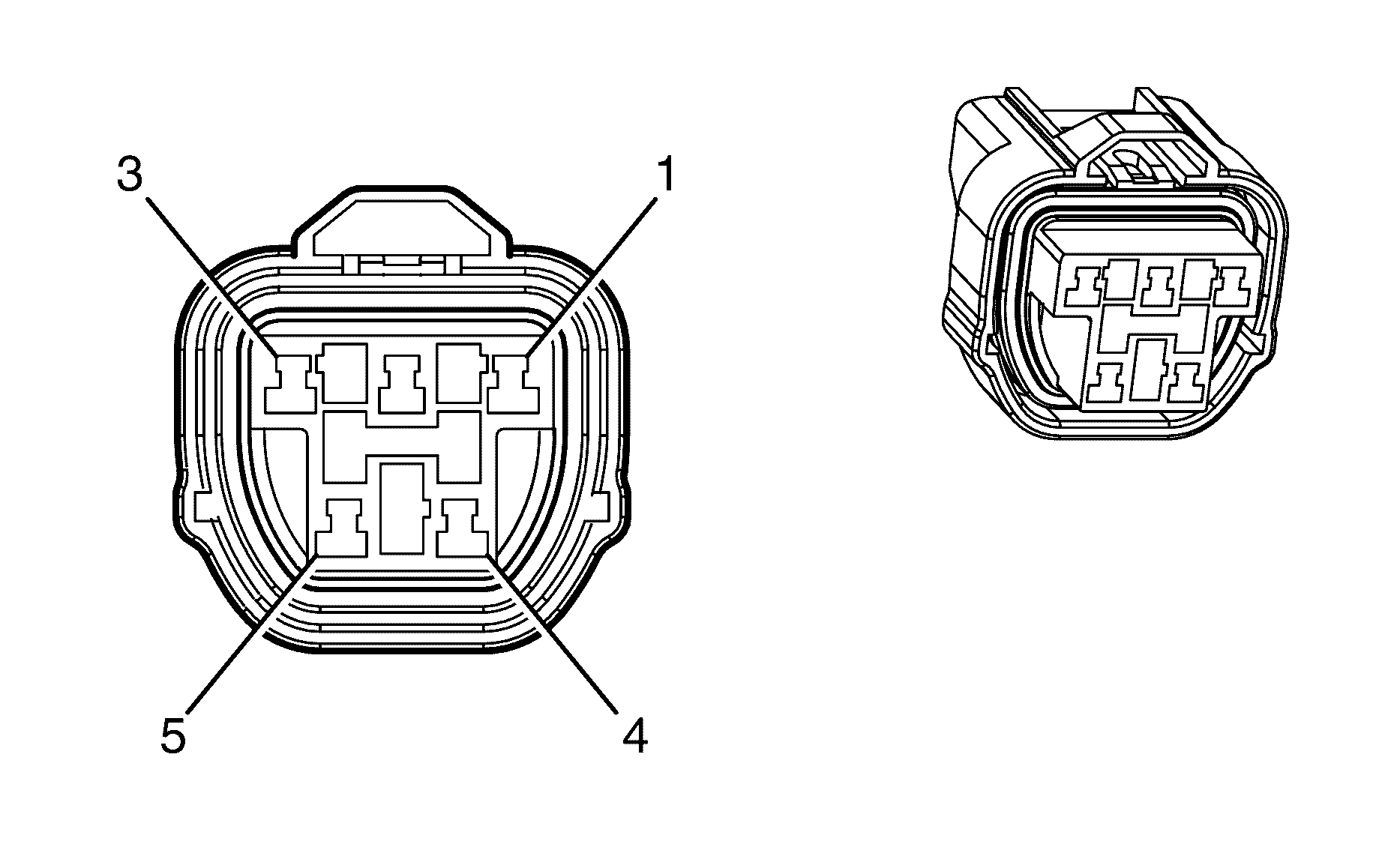
Connector Part Information
|
Terminal Part Information
|
Pin | Wire Color | Circuit No. | Function |
|---|---|---|---|
1 | 2 GY | 120 | Fuel Pump Supply Voltage |
2 | 0.5 PU | 1589 | Fuel Level Sensor Signal (Primary) |
3 | 2 BK | 1350 | Ground |
4 | 0.5 BN/YE | 452 | Low Reference |
5 | -- | -- | Not Used |
Fuel Tank Pressure (FTP) Sensor
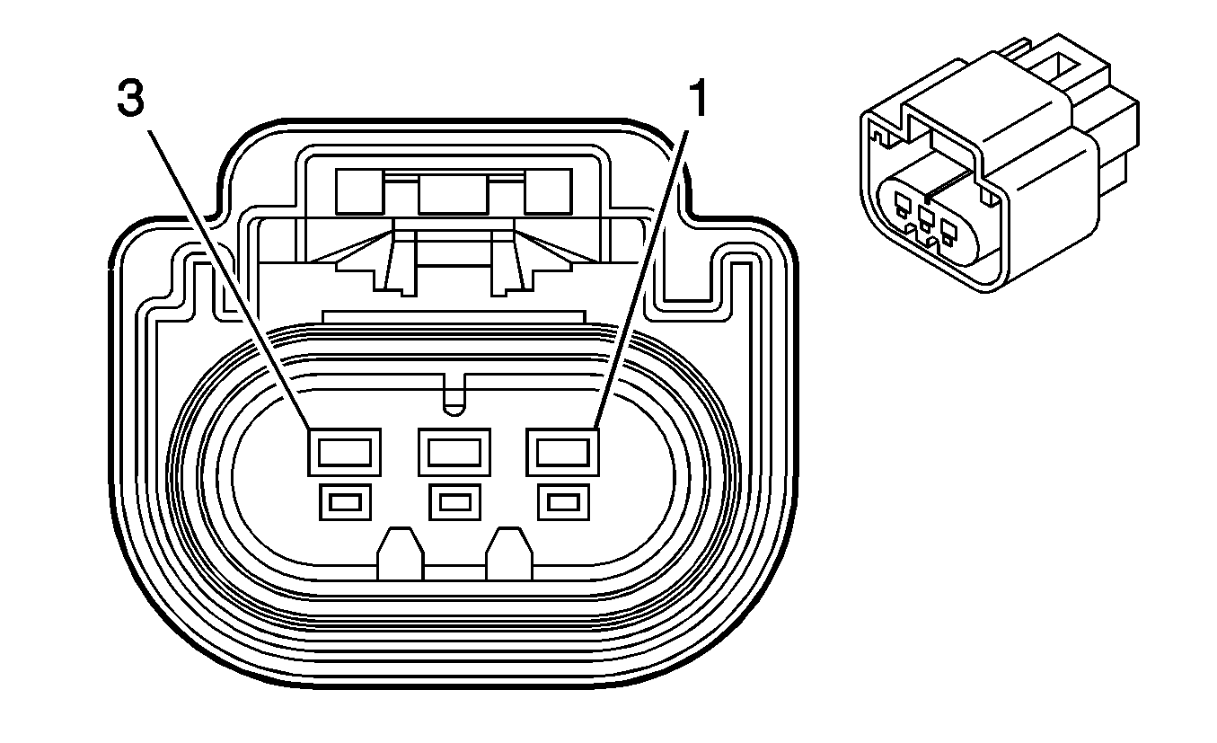
Connector Part Information
|
Terminal Part Information
|
Pin | Wire Color | Circuit No. | Function |
|---|---|---|---|
A | 0.5 D-GN | 890 | Fuel Tank Pressure Sensor Signal |
B | 0.5 BN/YE | 452 | Low Reference |
C | 0.5 GY | 2709 | 5-Volt Reference |
Generator X1 (L76)
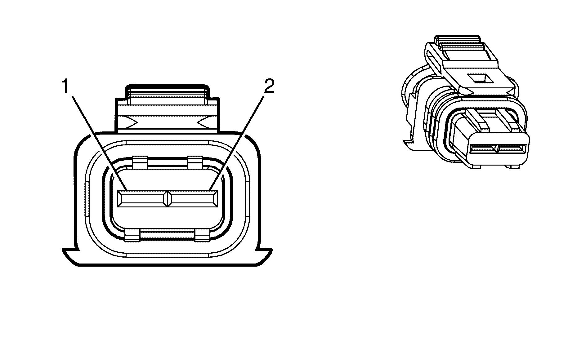
Connector Part Information
|
Terminal Part Information
|
Pin | Wire Color | Circuit No. | Function |
|---|---|---|---|
1 | 0.5 OG/WH | 225 | Generator Turn On Signal |
2 | 0.5 PU/WH | 23 | Generator Field Duty Cycle Signal |
Generator X1 (LY7)

Connector Part Information
|
Terminal Part Information
|
Pin | Wire Color | Circuit No. | Function |
|---|---|---|---|
1 | 0.5 OG/WH | 225 | Generator Turn On Signal |
2 | 0.5 PU/WH | 23 | Generator Field Duty Cycle Signal |
Generator X2
Terminal Part Information
|
Pin | Wire Color | Circuit No. | Function |
|---|---|---|---|
+ | 19 RD | 2 | Battery Positive Voltage |
19 RD | 2 | Battery Positive Voltage |
Headlamp and Panel Dimmer Switch
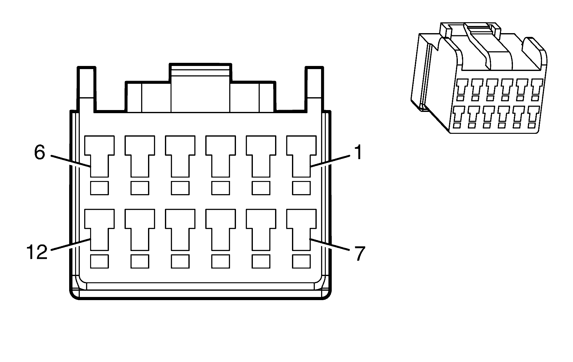
Connector Part Information
|
Terminal Part Information
|
Pin | Wire Color | Circuit No. | Function |
|---|---|---|---|
1 | 0.3 WH | 103 | Headlamp Switch Headlamps On Signal |
2 | -- | -- | Not Used |
3 | 0.3 D-GN | 306 | Headlamp Switch Headlamps Off Signal |
4 | 0.3 BK | 850 | Ground |
5 | 0.3 BN/WH | 301 | Park Lamp Switch On Signal |
6 | 0.3 OG | 192 | Front Fog Lamp Switch Signal |
7 | 0.3 GY/WH | 7389 | Headlamp Dimming Switch Down |
8 | 0.3 YE | 6817 | Interior Lights Dimming Switch |
9 | -- | -- | Not Used |
10 | 0.5 PK/BU | 1339 | Ignition 1 Voltage |
11 | -- | -- | Not Used |
12 | 0.3 GY/BU | 7388 | Headlamp Dimming Switch Up |
Headlamp - Left High Beam
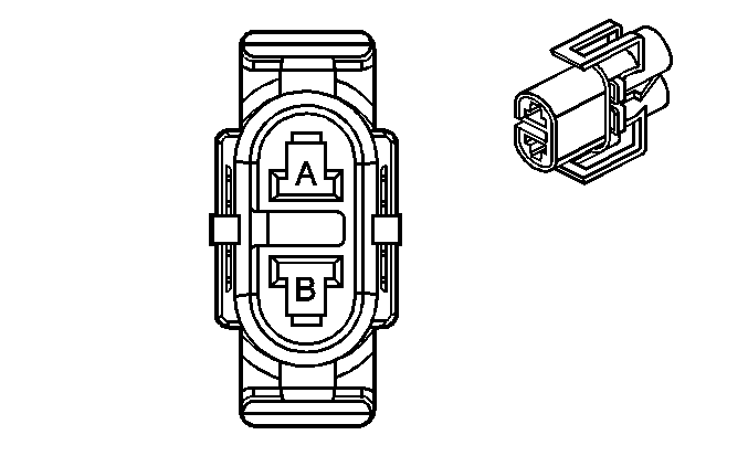
Connector Part Information
|
Terminal Part Information
|
Pin | Wire Color | Circuit No. | Function |
|---|---|---|---|
1 | 0.5 GY | 711 | Left Headlamp High Beam Control |
2 | 0.5 GY | 150 | Ground |
Headlamp - Left Low Beam

Connector Part Information
|
Terminal Part Information
|
Pin | Wire Color | Circuit No. | Function |
|---|---|---|---|
1 | 0.5 BN | 712 | Left Headlamp Low Beam Control |
2 | 0.5 BN | 150 | Ground |
Headlamp - Right High Beam

Connector Part Information
|
Terminal Part Information
|
Pin | Wire Color | Circuit No. | Function |
|---|---|---|---|
1 | 0.5 GY | 311 | Right Headlamp High Beam Control |
2 | 0.5 GY | 150 | Ground |
Headlamp - Right Low Beam

Connector Part Information
|
Terminal Part Information
|
Pin | Wire Color | Circuit No. | Function |
|---|---|---|---|
1 | 0.5 BN | 312 | Right Headlamp Low Beam Control |
2 | 0.5 BN | 150 | Ground |
Heated Oxygen Sensor (HO2S) Bank 1 Sensor 1 (LY7)
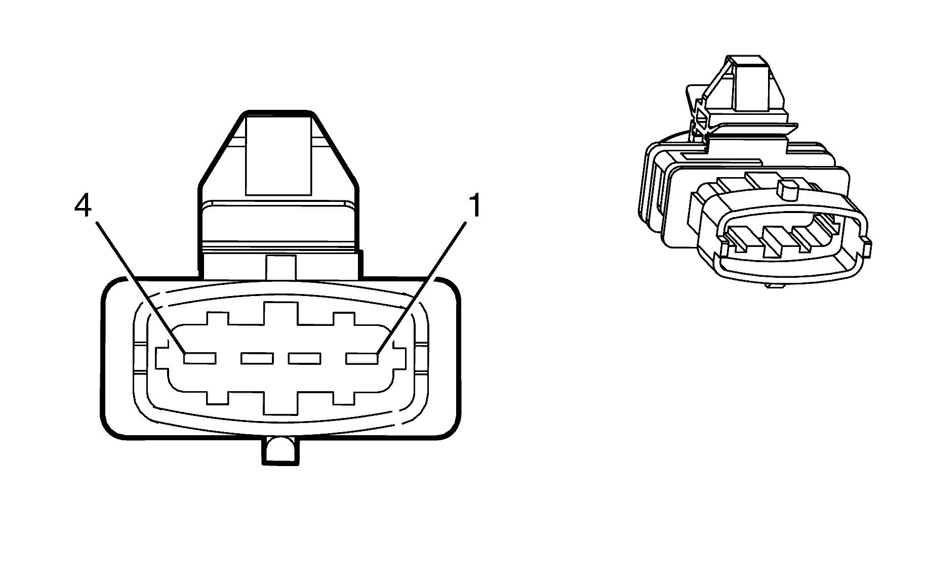
Connector Part Information
|
Terminal Part Information
|
Pin | Wire Color | Circuit No. | Function |
|---|---|---|---|
1 | 0.75 PK/BU | 5293 | Ignition 1 Voltage |
2 | 0.75 GY/WH | 3113 | HO2S Low Signal (Bank 1 Sensor 1) |
3 | 0.5 BN/YE | 1664 | HO2S Heater Low Control (Bank 1 Sensor 1) |
4 | 0.5 PU/WH | 1665 | Ignition 1 Voltage |
Heated Oxygen Sensor (HO2S) Bank 1 Sensor 1 (L76)
Connector Part Information
|
Terminal Part Information
|
Pin | Wire Color | Circuit No. | Function |
|---|---|---|---|
A | 0.5 BN/YE | 1664 | HO2S Low Signal [- Bank 1 Sensor 1] |
B | 0.5 PU/WH | 1665 | HO2S High Signal [- Bank 1 Sensor 1] |
C | 0.5 GY/WH | 3113 | HO2S Heater Low Control [- Bank 1 Sensor 1] |
D | 0.8 PK/BU | 5293 | Ignition 1 Voltage |
Heated Oxygen Sensor (HO2S) Bank 1 Sensor 2 (LY7)

Connector Part Information
|
Terminal Part Information
|
Pin | Wire Color | Circuit No. | Function |
|---|---|---|---|
1 | 0.75 PK/BU | 5294 | Ignition 1 Voltage |
2 | 0.75 GY/WH | 3122 | HO2S Heater Low Control (Bank 1 Sensor 2) |
3 | 0.5 BN/GN | 3121 | HO2S Low Signal (Bank 1 Sensor 2) |
4 | 0.5 PU | 3120 | HO2S High Signal (Bank 1 Sensor 2) |
Heated Oxygen Sensor (HO2S) Bank 1 Sensor 2 (L76)
Connector Part Information
|
Terminal Part Information
|
Pin | Wire Color | Circuit No. | Function |
|---|---|---|---|
A | 0.5 BN/WH | 1669 | HO2S Low Signal [- Bank 1 Sensor 2] |
B | 0.5 PU/WH | 1668 | HO2S High Signal [- Bank 1 Sensor 2] |
C | 0.5 BN | 2391 | HO2S Heater Low Control [- Bank 1 Sensor 2] |
D | 0.78 PK/BU | 5294 | Ignition 1 Voltage |
Heated Oxygen Sensor (HO2S) Bank 2 Sensor 1 (LY7)

Connector Part Information
|
Terminal Part Information
|
Pin | Wire Color | Circuit No. | Function |
|---|---|---|---|
1 | 0.75 PK/BU | 5293 | Ignition 1 Voltage |
2 | 0.75 L-GN | 3212 | HO2S Heater Low Control [- Bank 2 Sensor 1] |
3 | 0.5 BN/RD | 1667 | HO2S Low Signal [- Bank 2 Sensor 1] |
4 | 0.5 PU | 1666 | HO2S High Signal [- Bank 2 Sensor 1] |
Heated Oxygen Sensor (HO2S) Bank 2 Sensor 1 (L76)
Connector Part Information
|
Terminal Part Information
|
Pin | Wire Color | Circuit No. | Function |
|---|---|---|---|
A | 0.5 BN/RD | 1667 | HO2S Low Signal [- Bank 2 Sensor 1] |
B | 0.5 PU | 1666 | HO2S High Signal [- Bank 2 Sensor 1] |
C | 0.5 L-GN | 3212 | HO2S Heater Low Control [- Bank 2 Sensor 1] |
D | 0.8 PK/BU | 5293 | Ignition 1 Voltage |
Heated Oxygen Sensor (HO2S) Bank 2 Sensor 2 (LY7)

Connector Part Information
|
Terminal Part Information
|
Pin | Wire Color | Circuit No. | Function |
|---|---|---|---|
1 | 0.75 PK/BU | 5294 | Battery 1 Voltage |
2 | 0.75 OG/WH | 3223 | HO2S Heater Low Control (Bank 2 Sensor 2) |
3 | 0.5 BN/RD | 3221 | HO2S Low Signal (Bank 2 Sensor 2) |
4 | 0.5 PU | 3220 | HO2S High Signal (Bank 2 Sensor 2) |
Heated Oxygen Sensor (HO2S) Bank 2 Sensor 2 (L76)
Connector Part Information
|
Terminal Part Information
|
Pin | Wire Color | Circuit No. | Function |
|---|---|---|---|
A | 0.5 BN/WH | 1671 | HO2S Low Signal [- Bank 2 Sensor 2] |
B | 0.5 PU | 1670 | HO2S High Signal [- Bank 2 Sensor 2] |
C | 0.5 OG/WH | 3223 | HO2S Heater Low Control (Bank 2 Sensor 2) |
D | 0.78 PK/BU | 5294 | Ignition 1 Voltage |
Heated Seat Control Module - Driver (KA1)
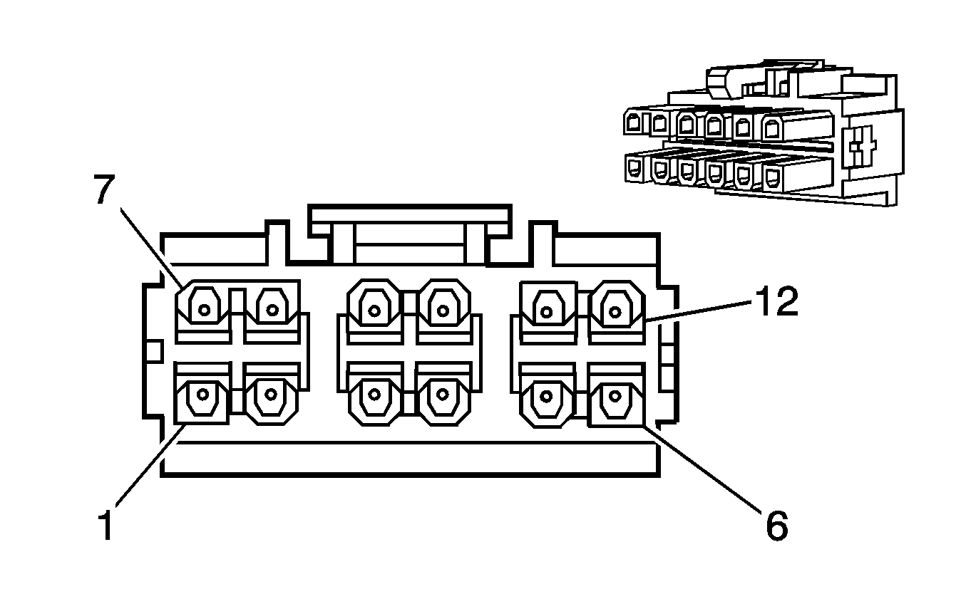
Connector Part Information
|
Terminal Part Information
|
Pin | Wire Color | Circuit No. | Function |
|---|---|---|---|
1 | -- | -- | Not Used |
2 | 0.5 RD/YE | 2050 | Low Reference |
3 | 0.5 PK | 1339 | Ignition 1 Voltage |
4 | PU/GN | -- | Low Reference |
5 | 0.35 BN | 1661 | Driver Heated Seat High Temperature Indicator Control |
6 | 0.35 OG/BK | 6177 | Passenger Heated Seat Intermediate Signal |
7 | -- | -- | Not Used |
8 | 0.5 D-GN/RD | 2077 | Heated Seat Cushion Element Supply Voltage |
9 | 0.35 PK/OG | 1501 | Driver Heated Seat High/Low Signal |
10 | -- | -- | Not Used |
11 | 0.35 WH/YE | 1662 | Driver Heated Seat Low Temperature Indicator Control |
12 | 0.35 WH/BK | 2079 | Heated Seat Cushion Temperature Sensor Signal |
Heated Seat Control Module - Passenger (KA1)

Connector Part Information
|
Terminal Part Information
|
Pin | Wire Color | Circuit No. | Function |
|---|---|---|---|
1 | -- | -- | Not Used |
2 | 0.5 RD/YE | 2050 | Low Reference |
3 | 0.5 PK | 1339 | Ignition 1 Voltage |
4 | PU/GN | -- | Low Reference |
5 | 0.35 BN | 1661 | Driver Heated Seat High Temperature Indicator Control |
6 | 0.35 OG/BK | 6177 | Passenger Heated Seat Intermediate Signal |
7 | -- | -- | Not Used |
8 | 0.5 D-GN/RD | 2077 | Heated Seat Cushion Element Supply Voltage |
9 | 0.35 PK/OG | 1501 | Driver Heated Seat High/Low Signal |
10 | -- | -- | Not Used |
11 | 0.35 WH/YE | 1662 | Driver Heated Seat Low Temperature Indicator Control |
12 | 0.35 WH/BK | 2079 | Heated Seat Cushion Temperature Sensor Signal |
Hood Ajar Switch
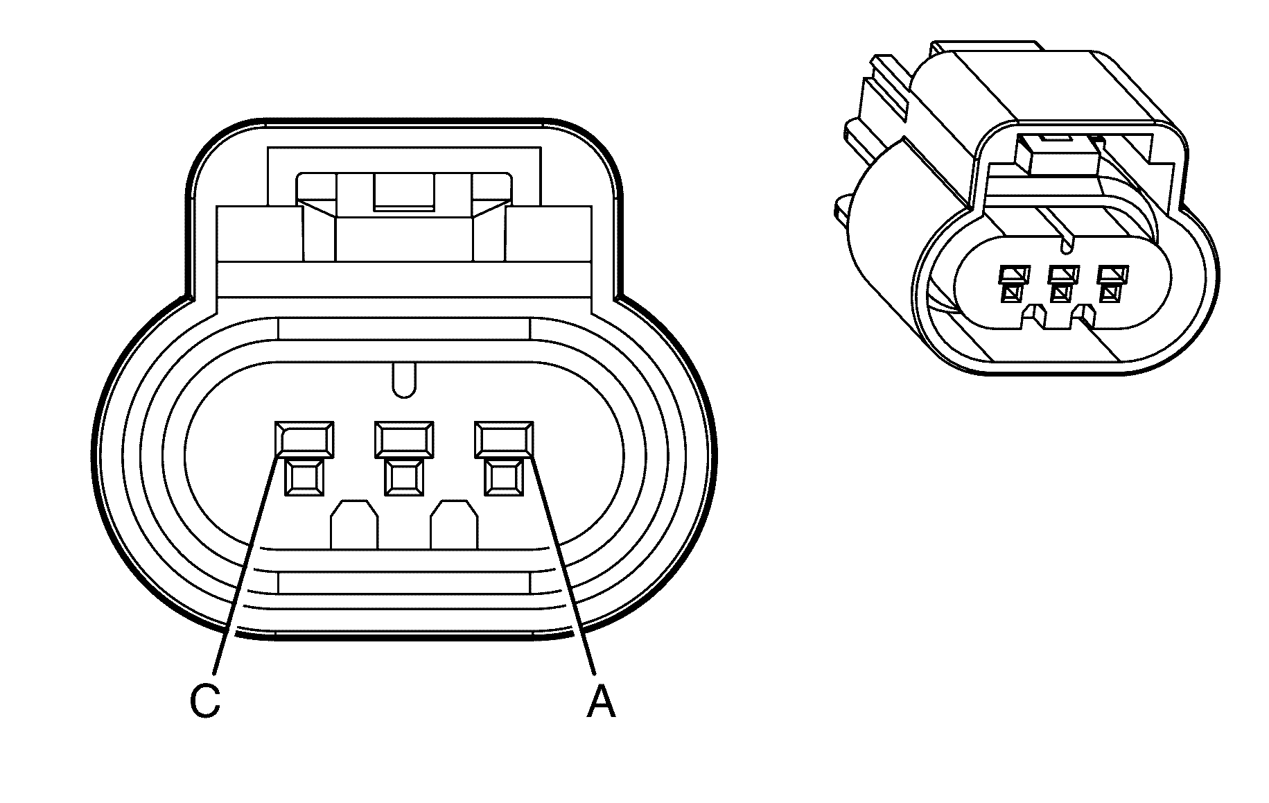
Connector Part Information
|
Terminal Part Information
|
Pin | Wire Color | Circuit No. | Function |
|---|---|---|---|
A | 0.3 PK/BK | 109 | Hood Ajar Switch Signal |
B | 0.3 PU | 5531 | Hood Closed Switch Signal |
C | 0.3 BK | 250 | Ground |
Horn - Left
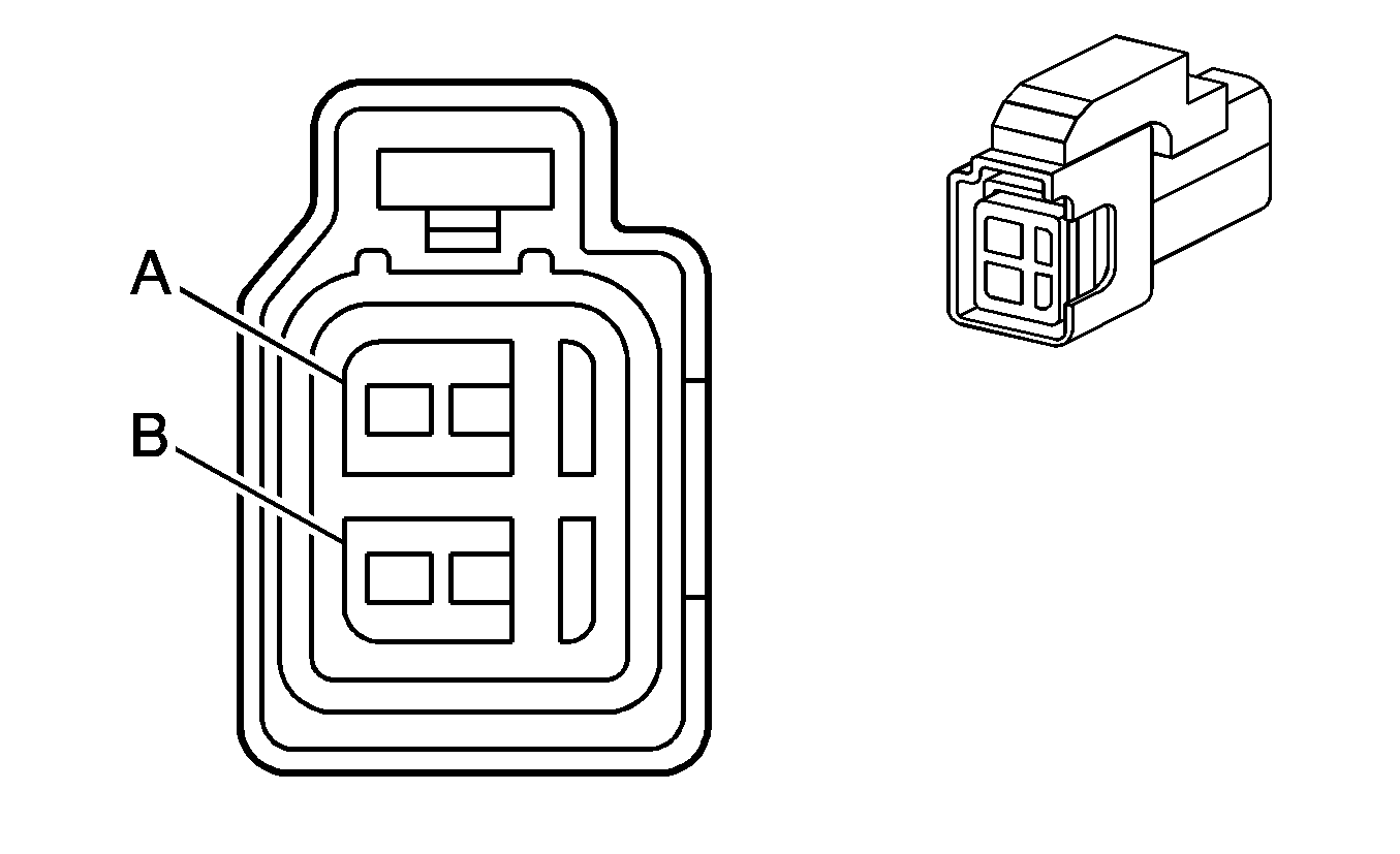
Connector Part Information
|
Terminal Part Information
|
Pin | Wire Color | Circuit No. | Function |
|---|---|---|---|
A | 0.75 D-GN | 1329 | Horn Fuse Supply Voltage |
B | 0.75 BK | 250 | Ground |
Horn - Right

Connector Part Information
|
|
Pin | Wire Color | Circuit No. | Function |
|---|---|---|---|
A | 0.75 D-GN | 1329 | Horn Fuse Supply Voltage |
B | 0.75 BK | 250 | Ground |
HVAC Control Module X1
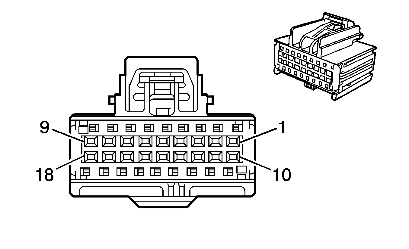
Connector Part Information
|
Terminal Part Information
|
Pin | Wire Color | Circuit No. | Function |
|---|---|---|---|
1 | 0.3 L-GN/BK | 735 | Ambient Air Temperature Sensor Signal (CJ2) |
2 | 0.3 D-GN | 734 | Inside Air Temperature Sensor Signal (CJ2) |
3 | 0.3 WH/BU | 193 | Rear Defog Relay Control |
4 | 0.3 YE | 1649 | Blower Motor Relay Supply Voltage |
5 | 0.5 GY/BK | 754 | Blower Motor Speed Control |
6 | 0.5 D-BU | 7393 | A/C Compressor Clutch Low Reference |
7 | 0.5 D-GN | 7392 | A/C Compressor Clutch Supply Voltage |
8 | 0.35 D-GN | 9207 | Low Speed GMLAN Serial Data |
9 | 0.5 PK | 1039 | Ignition 1 Voltage |
10 | 0.85 BK | 850 | Ground |
11 | 0.3 BN | 61 | Low Reference (CJ2) |
12 | 0.3 L-BU/BK | 7425 | Left Solar Sensor (CJ2) |
13 | 0.3 GY | 7424 | Right Solar Sensor (CJ2) |
14-17 | -- | -- | Not Used |
18 | 0.75 OG/GN | 2240 | Battery Positive Voltage |
HVAC Control Module X2
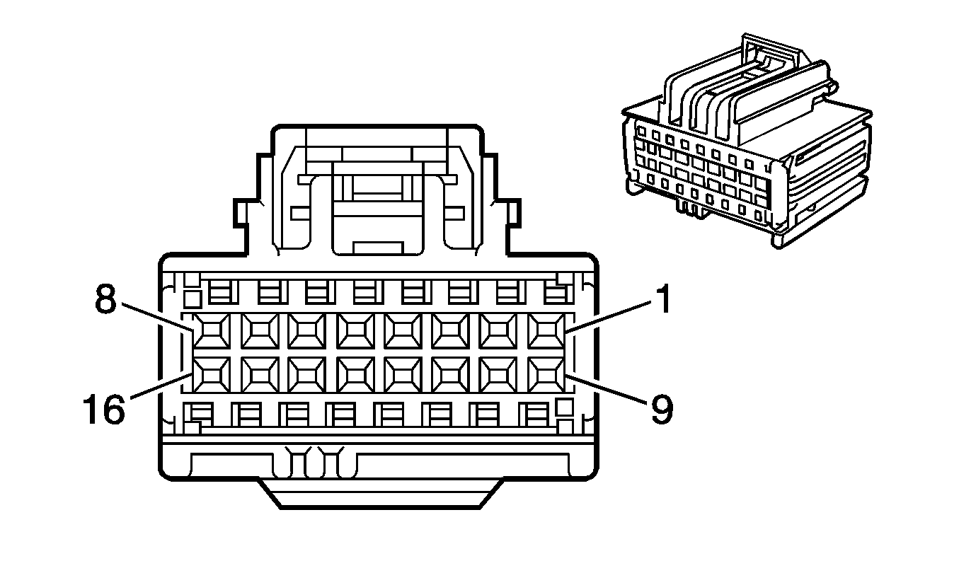
Connector Part Information
|
Terminal Part Information
|
Pin | Wire Color | Circuit No. | Function |
|---|---|---|---|
1 | 0.5 YE | -- | -- |
2 | 0.5 WH/OG | -- | -- |
3 | RD | -- | -- |
4 | 0.5 WH | -- | -- |
5 | 0.5 GY/OG | -- | -- |
6 | -- | -- | -- |
7 | 0.5 OG | -- | -- |
8 | 0.5 D-BU | -- | -- |
9 | 0.5 PK | -- | -- |
10 | 0.5 YE/BK | -- | -- |
11 | 0.5 WH/BU | -- | -- |
12 | 0.5 PU | -- | -- |
13 | 0.5 D-BU/WH | -- | -- |
14 | 0.5 RD/WH | -- | -- |
15 | 0.5 D-GN/YE | -- | -- |
16 | 0.5 GY | -- | -- |
HVAC Control Module X3 (CJ2)

Connector Part Information
|
Terminal Part Information
|
Pin | Wire Color | Circuit No. | Function |
|---|---|---|---|
1 | 0.5 BU | 2215 | Auxiliary Mode Door Control |
2 | 0.5 OG | 454 | Auxiliary Mode Door Control |
3-6 | -- | -- | Not Used |
7 | 0.5 GY/RD | 1814 | Lower Mode Door Position Signal |
8-16 | -- | -- | Not Used |
Ignition Coil 1 (LY7)
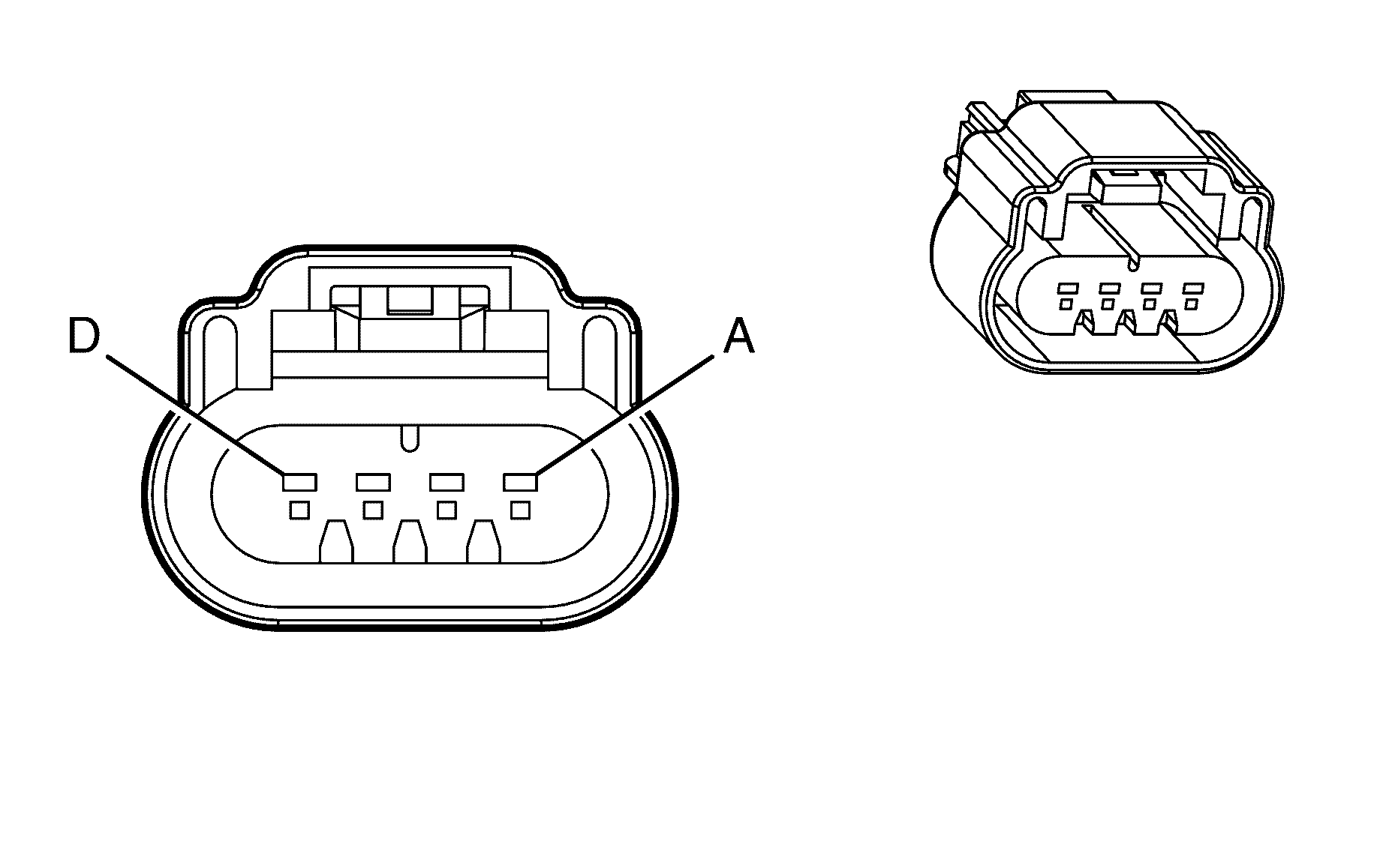
Connector Part Information
|
Terminal Part Information
|
Pin | Wire Color | Circuit No. | Function |
|---|---|---|---|
A | 0.75 BK | 2550 | Ground |
B | 0.5 PU | 6413 | Low Reference |
C | 0.5 PU | 2121 | IC 1 Control |
D | 0.75 PK/BU | 5291 | Ignition 1 Voltage |
Ignition Coil 1 (L76)

Connector Part Information
|
Terminal Part Information
|
Pin | Wire Color | Circuit No. | Function |
|---|---|---|---|
A | 0.8 BK | 151 | Ground |
B | 0.5 BN | 2129 | IC 1 Control |
C | 0.5 PU | 2121 | IC 1 Control |
D | 0.8 PK | 39 | Ignition 1 Voltage |
Ignition Coil 2 (LY7)

Connector Part Information
|
Terminal Part Information
|
Pin | Wire Color | Circuit No. | Function |
|---|---|---|---|
A | 0.75 BK | 2650 | Ground |
B | 0.5 PK | 6414 | Low Reference |
C | 0.5 OG/WH | 2122 | IC 2 Control |
D | 0.75 PK | 5292 | Ignition 1 Voltage |
Ignition Coil 2 (L76)

Connector Part Information
|
Terminal Part Information
|
Pin | Wire Color | Circuit No. | Function |
|---|---|---|---|
A | 0.8 BK | 151 | Ground |
B | 0.5 BN | 2129 | IC 2 Control |
C | 0.5 RD | 2127 | IC 2 Control |
D | 0.8 PK | 39 | Ignition 1Voltage |
Ignition Coil 3 (LY7)

Connector Part Information
|
Terminal Part Information
|
Pin | Wire Color | Circuit No. | Function |
|---|---|---|---|
A | 0.75 BK | 2550 | Ground |
B | 0.5 PU | 6413 | Low Reference |
C | 0.5 L-BU | 2123 | IC 3 Control |
D | 0.75 PK/BU | 5291 | Ignition 1 Voltage |
Ignition Coil 3 (L76)

Connector Part Information
|
Terminal Part Information
|
Pin | Wire Color | Circuit No. | Function |
|---|---|---|---|
A | 0.8 BK | 151 | Ground |
B | 0.5 BN | 2129 | IC 3 Control |
C | 0.5 L-BU | 2123 | IC 3 Control |
D | 0.8 PK | 39 | Ignition 1Voltage |
Ignition Coil 4 (LY7)

Connector Part Information
|
Terminal Part Information
|
Pin | Wire Color | Circuit No. | Function |
|---|---|---|---|
A | 0.75 BK | 2650 | Ground |
B | 0.5 PK | 6414 | Low Reference |
C | 0.5 D-GN/WH | 2124 | IC 4 Control |
D | 0.75 PK | 5292 | Ignition 1 Voltage |
Ignition Coil 4 (L76)

Connector Part Information
|
Terminal Part Information
|
Pin | Wire Color | Circuit No. | Function |
|---|---|---|---|
A | 0.8 BK | 151 | Ground |
B | 0.5 BN | 2129 | IC 4 Control |
C | 0.5 D-GN | 2125 | IC 4 Control |
D | 0.8 PK | 39 | Ignition 1Voltage |
Ignition Coil 5 (LY7)

Connector Part Information
|
Terminal Part Information
|
Pin | Wire Color | Circuit No. | Function |
|---|---|---|---|
A | 0.75 BK | 2550 | Ground |
B | 0.5 PU | 6413 | Low Reference |
C | 0.5 D-GN/RD | 2125 | IC 5 Control |
D | 0.75 PK/BU | 5291 | Ignition 1 Voltage |
Ignition Coil 5 (L76)

Connector Part Information
|
Terminal Part Information
|
Pin | Wire Color | Circuit No. | Function |
|---|---|---|---|
A | 0.8 BK | 151 | Ground |
B | 0.5 BN | 2129 | IC 5 Control |
C | 0.5 D-GN | 2125 | IC 5 Control |
D | 0.8 PK | 39 | Ignition 1Voltage |
Ignition Coil 6 (LY7)

Connector Part Information
|
Terminal Part Information
|
Pin | Wire Color | Circuit No. | Function |
|---|---|---|---|
A | 0.75 BK | 2650 | Ground |
B | 0.5 PK | 6414 | Low Reference |
C | 0.5 L-BU/WH | 2126 | IC 6 Control |
D | 0.75 PK | 5292 | Ignition 1 Voltage |
Ignition Coil 6 (L76)

Connector Part Information
|
Terminal Part Information
|
Pin | Wire Color | Circuit No. | Function |
|---|---|---|---|
A | 0.8 BK | 151 | Ground |
B | 0.5 BN | 2129 | IC 6 Control |
C | 0.5 L-BU | 2123 | IC 6 Control |
D | 0.8 PK | 39 | Ignition 1Voltage |
Ignition Coil 7 (L76)

Connector Part Information
|
Terminal Part Information
|
Pin | Wire Color | Circuit No. | Function |
|---|---|---|---|
A | 0.8 BK | 151 | Ground |
B | 0.5 BN | 2129 | IC 7 Control |
C | 0.5 RD | 2127 | IC 7 Control |
D | 0.8 PK | 39 | Ignition 1Voltage |
Ignition Coil 8 (L76)

Connector Part Information
|
Terminal Part Information
|
Pin | Wire Color | Circuit No. | Function |
|---|---|---|---|
A | 0.8 BK | 151 | Ground |
B | 0.5 BN | 2129 | IC 8 Control |
C | 0.5 PU | 2121 | IC 8 Control |
D | 0.8 PK | 39 | Ignition 1 Voltage |
Ignition Key Cylinder Lamp
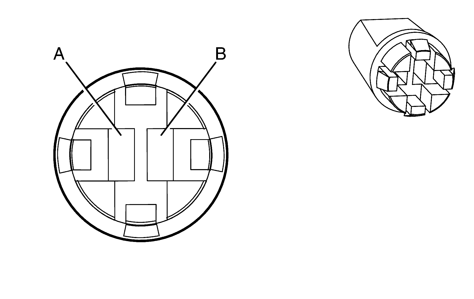
Connector Part Information
|
Terminal Part Information
|
Pin | Wire Color | Circuit No. | Function |
|---|---|---|---|
A | 0.5 D-BU/WH | 149 | Courtesy Lamp Supply Voltage |
B | 0.5 BK | 850 | Ground |
Ignition Lock Cylinder Control Solenoid
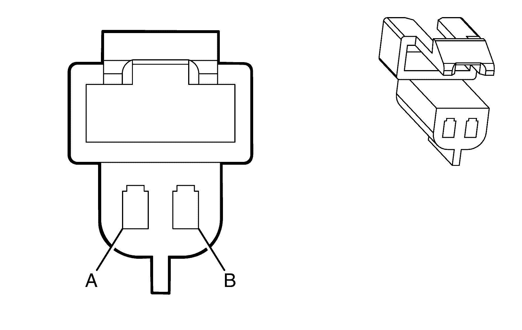
|
Terminal Part Information
|
Pin | Wire Color | Circuit No. | Function |
|---|---|---|---|
A | 0.5 BN | 443 | Accessory Voltage |
B | 0.3 PU/WH | 1630 | Steering Column Key Cylinder Lock Solenoid Control |
Ignition Switch
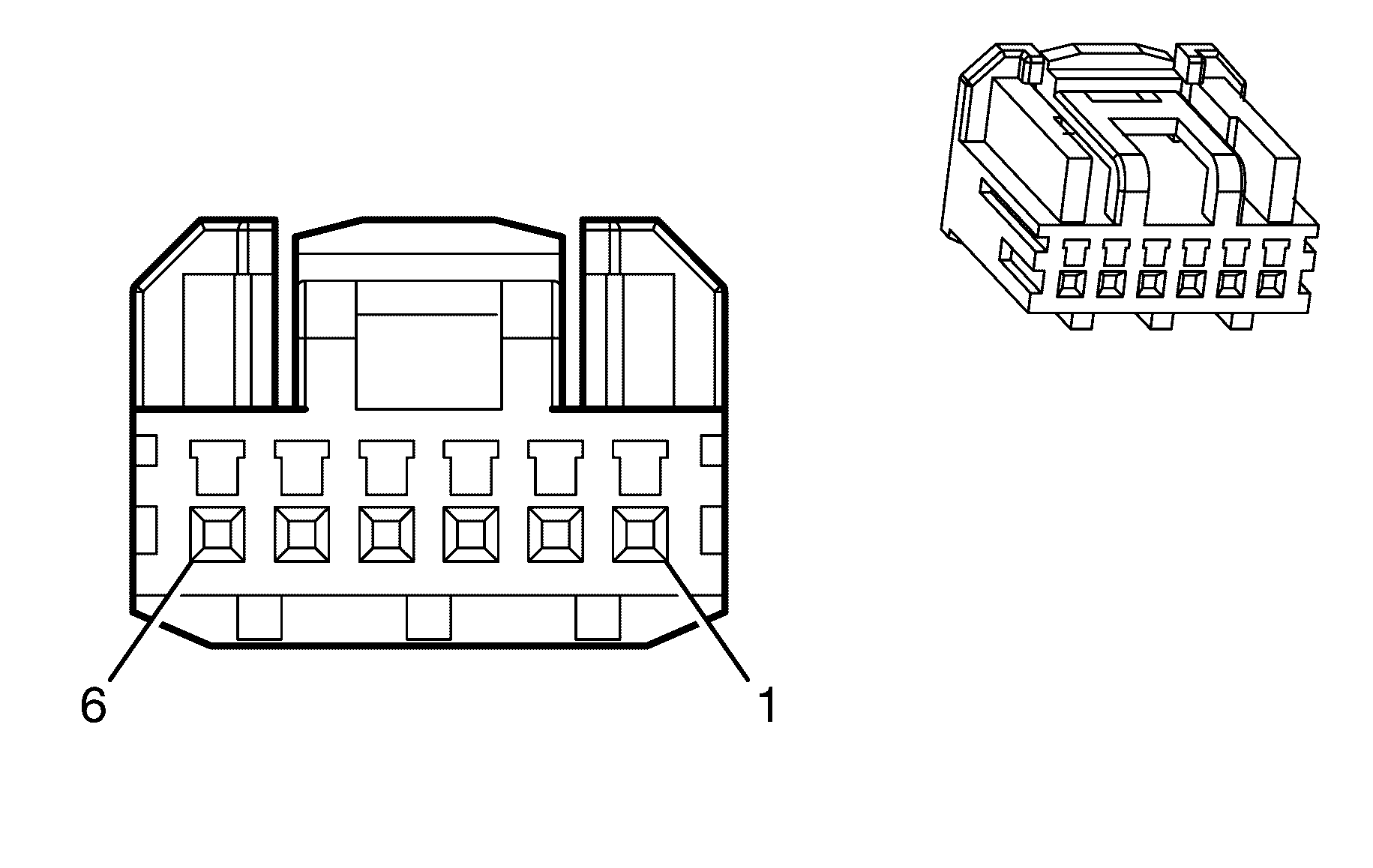
Connector Part Information
|
Terminal Part Information
|
Pin | Wire Color | Circuit No. | Function |
|---|---|---|---|
1 | 0.3 PK | 3 | Run/Crank Voltage |
2 | 0.5 OG/BK | 1040 | Battery Positive Voltage |
3 | 0.3 BN | 4 | Ignition 1 Voltage |
4 | 0.3 WH | 1390 | Ignition Key Resistor Low Reference |
5 | -- | -- | Not Used |
6 | 0.3 WH/BK | 1073 | Ignition Key Resistor Signal |
Inflatable Restraint Front End Sensor - Left
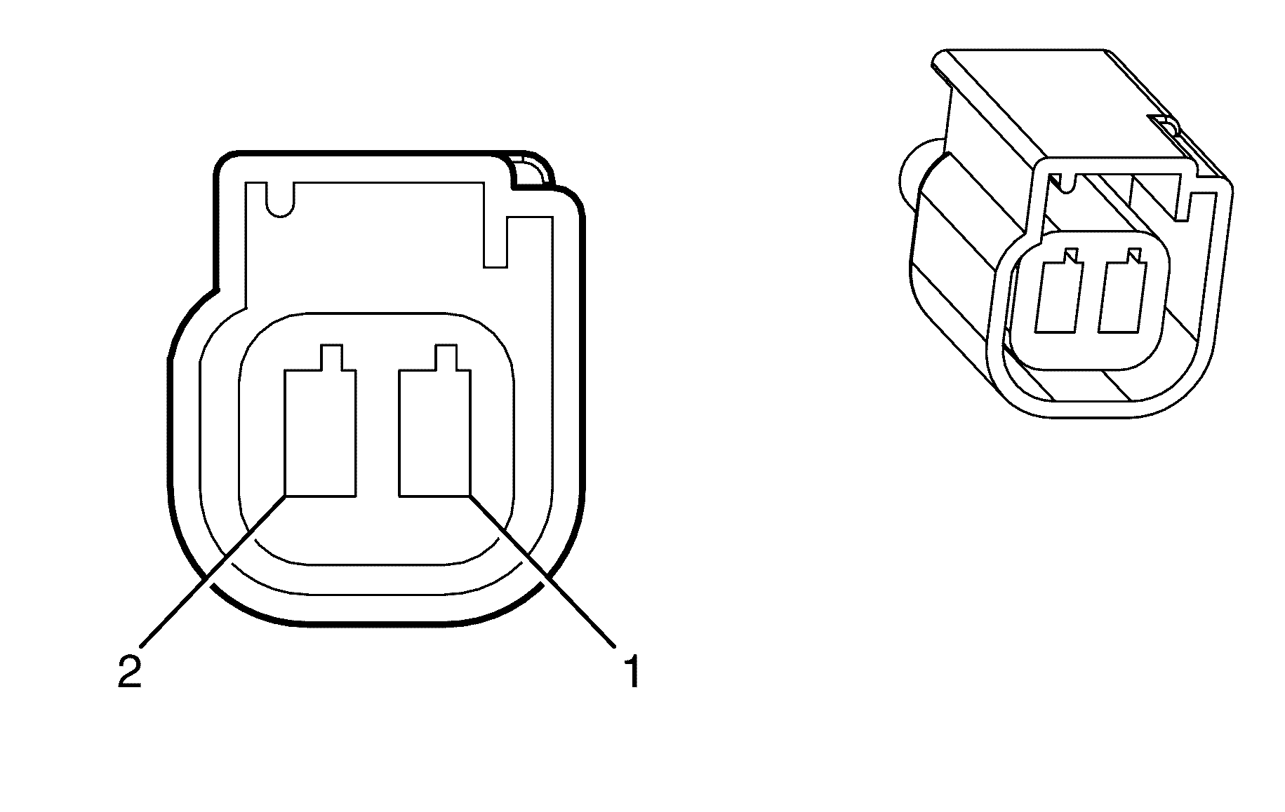
Connector Part Information
|
Terminal Part Information
|
Pin | Wire Color | Circuit No. | Function |
|---|---|---|---|
1 | 0.3 YE | 354 | Discriminating Sensor - Signal |
2 | 0.3 BN/YE | 5045 | Discriminating Sensor - Low Reference |
Inflatable Restraint Front End Sensor - Right

Connector Part Information
|
Terminal Part Information
|
Pin | Wire Color | Circuit No. | Function |
|---|---|---|---|
1 | 0.3 D-GN | 1409 | Discriminating Sensor - Right Signal |
2 | 0.3 GY | 5600 | Discriminating Sensor - Low Reference |
Inflatable Restraint Front Passenger Presence System (PPS) Module X1
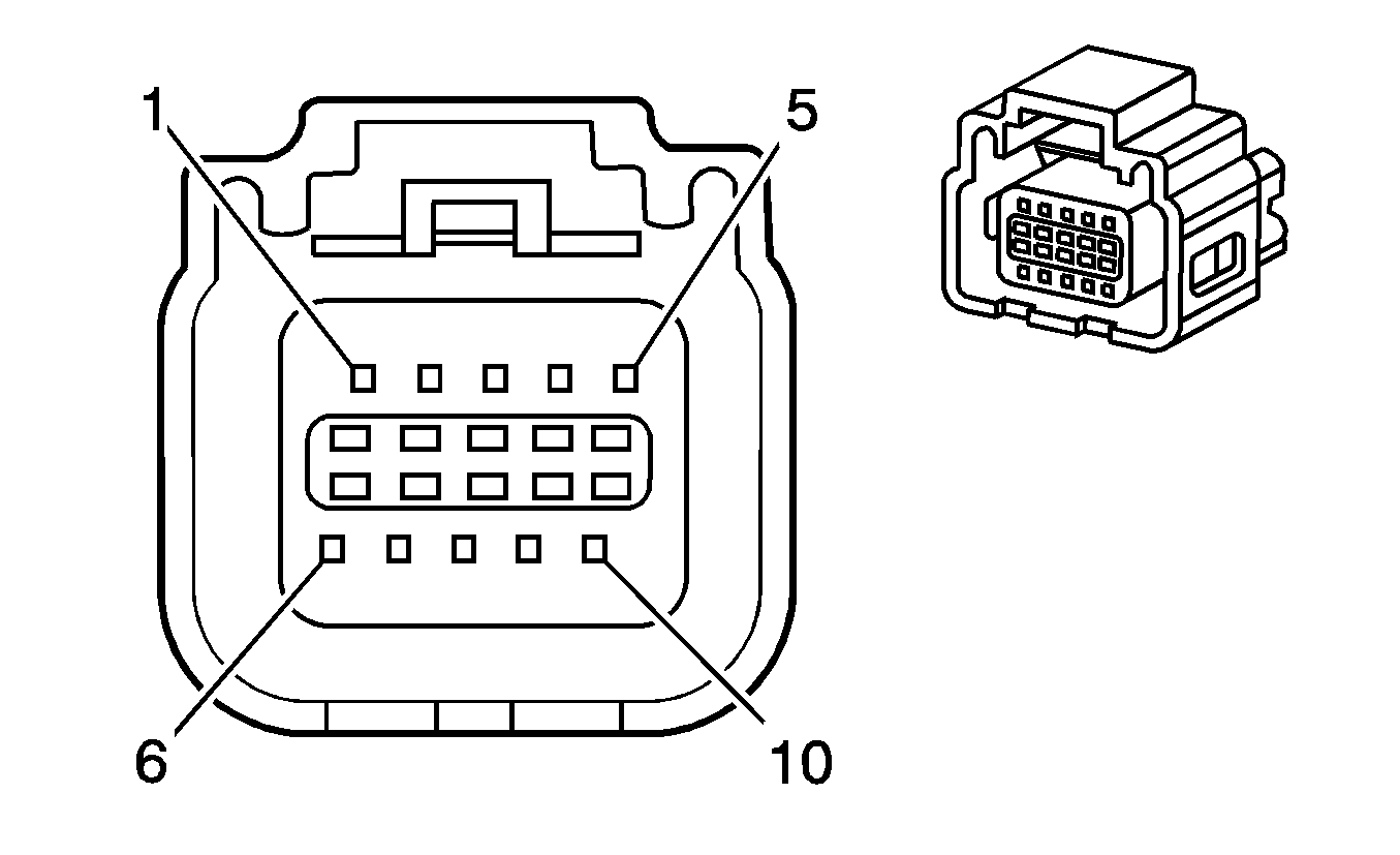
Connector Part Information
|
Terminal Part Information
|
Pin | Wire Color | Circuit No. | Function |
|---|---|---|---|
1 | 0.35 WH/PK | 3940 | PPS Supply Voltage |
2 | 0.5 BK/WH | 1751 | Ground |
3 | -- | -- | Not Used |
4 | 0.35 D-GN/RD | 5060 | Low Speed GMLAN Serial Data |
5-10 | -- | -- | Not Used |
Inflatable Restraint Front Passenger Presence System (PPS) Module X2
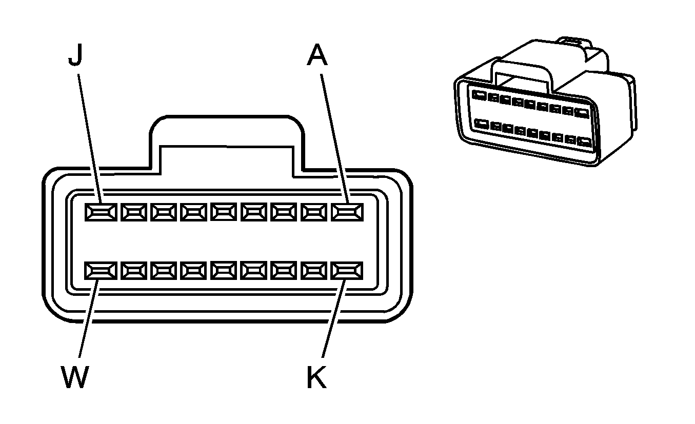
Connector Part Information
|
Terminal Part Information
|
Pin | Wire Color | Circuit No. | Function |
|---|---|---|---|
1 | CLR | -- | -- |
2 | CLR | -- | -- |
3 | CLR | -- | -- |
4 | CLR | -- | -- |
5 | CLR | -- | -- |
Inflatable Restraint I/P Module X1
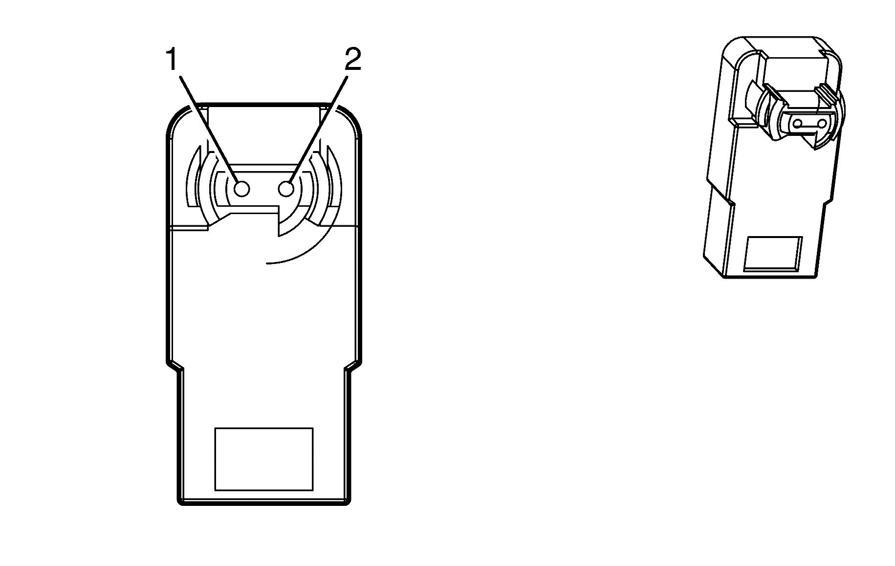
Connector Part Information
|
Terminal Part Information
|
Pin | Wire Color | Circuit No. | Function |
|---|---|---|---|
1 | 0.5 D-BU | 3024 | I/P Module - Stage 1 - Low Control |
2 | 0.5 YE | 3025 | I/P Module - Stage 1 - High Control |
Inflatable Restraint I/P Module X2

Connector Part Information
|
Terminal Part Information
|
Pin | Wire Color | Circuit No. | Function |
|---|---|---|---|
1 | 0.5 PU | 3026 | I/P Module - Stage 2 - Low Control |
2 | 0.5 D-GN | 3027 | I/P Module - Stage 2 - High Control |
Inflatable Restraint Roof Rail Module - Left
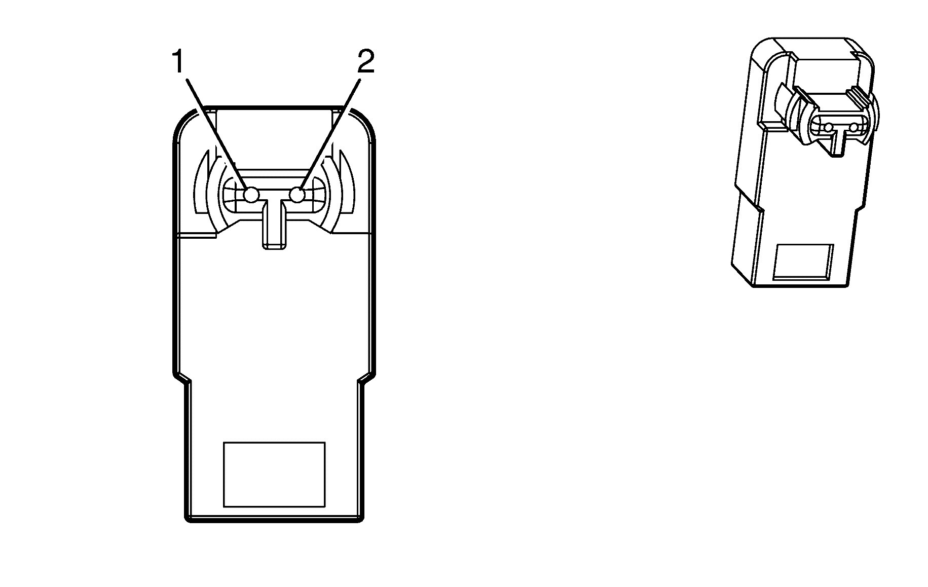
Connector Part Information
|
Terminal Part Information
|
Pin | Wire Color | Circuit No. | Function |
|---|---|---|---|
1 | 0.5 BN/BK | 5019 | Roof Rail Module - Left - High Control |
2 | 0.5 PK | 5020 | Roof Rail Module - Left - Low Control |
Inflatable Restraint Roof Rail Module - Right

Connector Part Information
|
Terminal Part Information
|
Pin | Wire Color | Circuit No. | Function |
|---|---|---|---|
1 | 0.5 PU/YE | 5021 | Roof Rail Module - Right - High Control |
2 | 0.5 WH/BK | 5022 | Roof Rail Module - Right - Low Control |
Inflatable Restraint Seat Position Sensor - Driver

Connector Part Information
|
Terminal Part Information
|
Pin | Wire Color | Circuit No. | Function |
|---|---|---|---|
A | 0.3 PK/BU | 5055 | Seat Position Sensor- Left - Signal |
B | 0.3 PU/WH | 5057 | Seat Belt Switch - Right Front - Low Reference |
Inflatable Restraint Seat Position Sensor - Passenger

Connector Part Information
|
Terminal Part Information
|
Pin | Wire Color | Circuit No. | Function |
|---|---|---|---|
A | 0.3 PK/BU | 5056 | Seat Position Sensor- Right - Signal |
B | 0.3 PU/WH | 5057 | Seat Belt Switch - Right Front - Low Reference |
Inflatable Restraint Sensing and Diagnostic Module (SDM) X1
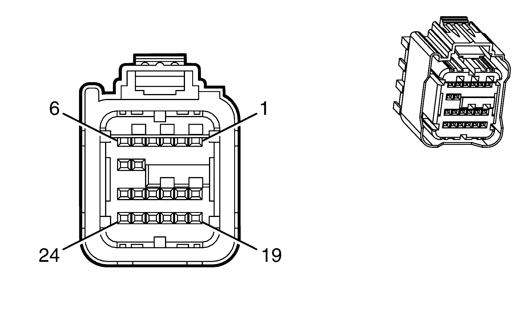
Connector Part Information
|
Terminal Part Information
|
Pin | Wire Color | Circuit No. | Function |
|---|---|---|---|
1 | 0.3 BN | 3020 | Steering Wheel Module - Stage1 - Low Control |
2 | 0.3 BN/RD | 3021 | Steering Wheel Module - Stage1 - High Control |
3 | 0.3 WH | 3023 | Steering Wheel Module - Stage2 - High Control |
4 | 0.3 PK | 3022 | Steering Wheel Module - Stage2 - Low Control |
5 | 0.3 YE/BK | 2138 | Side Impact Module -LF - Low Control |
6 | 0.3 BN | 2137 | Side Impact Module -LF - High Control |
7-18 | -- | -- | Not Used |
19 | 0.3 BN/YE | 5045 | Discriminating Sensor - Low Reference |
20 | 0.3 YE | 354 | Discriminating Sensor - Signal |
21 | 0.5 PK/BU | 339 | Ignition 1 Voltage |
22 | 0.5 OG/YE | 1340 | Battery Positive Voltage |
23 | -- | -- | Not Used |
24 | 0.5 BK/WH | 1751 | Ground |
Inflatable Restraint Sensing and Diagnostic Module (SDM) X2
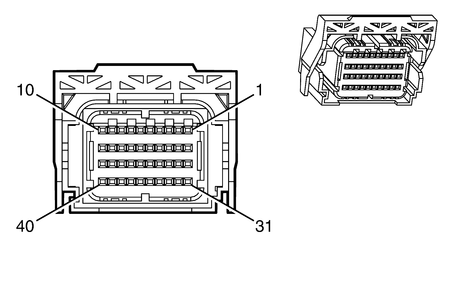
Connector Part Information
|
Terminal Part Information
|
Pin | Wire Color | Circuit No. | Function |
|---|---|---|---|
1 | 0.5 BN/BK | 5019 | Roof Rail Module - Left - High Control |
2 | 0.5 PK | 5020 | Roof Rail Module - Left - Low Control |
3 | 0.5 WH/BK | 5022 | Roof Rail Module - Right - Low Control |
4 | 0.5 PU/YE | 5021 | Roof Rail Module -Right - High Control |
5 | 0.3 BK/WH | 2135 | Side Impact Module -RF - High Control |
6 | 0.3 L-GN | 2136 | Side Impact Module - RF - Low Control |
7 | 0.3 PU | 3026 | I/P Module - Stage 2 - Low Control |
8 | 0.3 D-GN | 3027 | I/P Module - Stage 2 - High Control |
9 | 0.3 YE | 3025 | I/P Module - Stage 1 - High Control |
10 | 0.3 D-BU | 3024 | I/P Module - Stage 1 - Low Control |
11 | 0.3 OG/GN | 7203 | Driver Seat Belt Pretensioner Retractor - High Control |
12 | 0.3 WH | 7206 | Driver Seat Belt Pretensioner Retractor - Low Control |
13 | 0.3 PU/GN | 7205 | Passenger Seat Belt Pretensioner Retractor - High Control |
14 | 0.3 OG/BU | 7204 | Passenger Seat Belt Pretensioner Retractor - Low Control |
15 | 0.3 BK/WH | 2118 | Seat Belt Pretensioner - Left High Control |
16 | 0.3 OG/BK | 2119 | Seat Belt Pretensioner - Left Low Control |
17 | 0.3 OG | 2117 | Seat Belt Pretensioner - Right Low Control |
18 | 0.3 L-GN | 2116 | Seat Belt Pretensioner - Right High Control |
19-22 | -- | -- | Not Used |
23 | 0.3 D-GN | 1409 | Discriminating Sensor - Right Signal |
24 | 0.3 GY | 5600 | Discriminating Sensor - Low Reference |
25 | 0.3 PU/WH | 6628 | Side Impact Sensing Module - Right - Low Reference |
26 | 0.3 WH | 2132 | Side Impact Sensing Module - Left - Signal |
27 | 0.3 D-GN | 2134 | Side Impact Sensing Module - Right - Signal |
28 | 0.3 WH/BK | 6629 | Side Impact Sensing Module - Left - Low Reference |
29-32 | -- | -- | Not Used |
33 | 0.3 L-BU | 5056 | Passenger Seat Position Sensor |
34 | 0.3 PK | 5057 | Passenger Seat Position Sensor Return |
35 | 0.3 L-GN | 5055 | Seat Position Sensor - Left - Signal |
36 | 0.3 BK/WH | 238 | Seat Belt Switch - Left |
37 | 0.3 OG | 1362 | Seat Belt Switch - Right Signal |
38 | 0.3 D-BU | 1363 | Seat Belt Switch - Left - Low Reference |
39 | -- | -- | Not Used |
40 | 0.35 D-GN | 5060 | Low Speed GMLAN Serial Data |
Inflatable Restraint Side Impact Module - Left X1
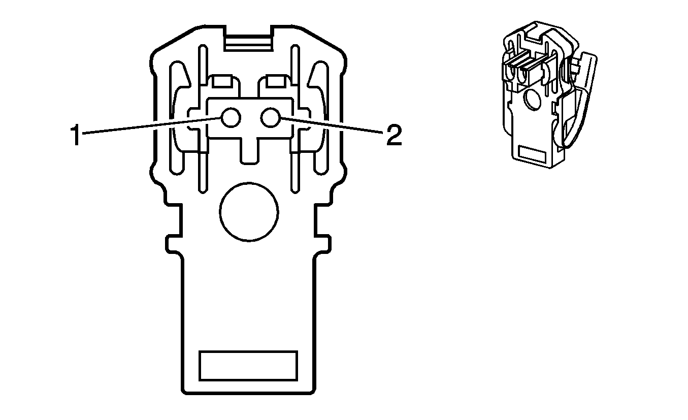
Connector Part Information
|
Terminal Part Information
|
Pin | Wire Color | Circuit No. | Function |
|---|---|---|---|
1 | 0.3 BN | 2137 | Side Impact Module - Left Front - High Control |
2 | 0.3 YE/BK | 2138 | Side Impact Module - Left Front - Low Control |
Inflatable Restraint Side Impact Module - Left X2
Terminal Part Information
|
Pin | Wire Color | Circuit No. | Function |
|---|---|---|---|
A | 0.3 BK/WH | 1751 | Ground |
Inflatable Restraint Side Impact Module - Right X1

Connector Part Information
|
Terminal Part Information
|
Pin | Wire Color | Circuit No. | Function |
|---|---|---|---|
1 | 0.3 BK/WH | 2135 | Side Impact Module - Right Front - High Control |
2 | 0.3 L-GN | 2136 | Side Impact Module - Right Front - Low Control |
Inflatable Restraint Side Impact Module - Right X2
Terminal Part Information
|
Pin | Wire Color | Circuit No. | Function |
|---|---|---|---|
A | 0.3 BK/WH | 1751 | Ground |
Inflatable Restraint Side Impact Sensor (SIS) - Left

Connector Part Information
|
Terminal Part Information
|
Pin | Wire Color | Circuit No. | Function |
|---|---|---|---|
1 | 0.3 WH | 2132 | Side Impact Sensing Module - Left - Signal |
2 | 0.3 PU/WH | 6628 | Side Impact Sensing Module - Left - Low Reference |
Inflatable Restraint Side Impact Sensor (SIS) - Right

Connector Part Information
|
Terminal Part Information
|
Pin | Wire Color | Circuit No. | Function |
|---|---|---|---|
1 | 0.3 D-GN | 2134 | Side Impact Sensing Module - Right - Signal |
2 | 0.3 WH/BK | 6629 | Side Impact Sensing Module - Right - Low Reference |
Inflatable Restraint Steering Wheel Module Coil X1
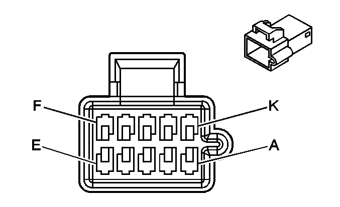
Connector Part Information
|
Terminal Part Information
|
Pin | Wire Color | Circuit No. | Function |
|---|---|---|---|
A | 0.3 GY/BU | 7367 | Right Steering Wheel Scroll 2 |
B | 0.3 BN/GN | 7364 | Right Steering Wheel Scroll 1 |
C | 0.3 BN | 7312 | Left Steering Wheel Scroll 1 |
D | 0.3 L-BU | 7313 | Left Steering Wheel Scroll 2 |
E | 0.3 BN/WH | 897 | DIC Switch Low Reference |
F | 0.3 OG/BK | 5201 | Steering Wheel Controls Signal |
G | 0.3 BK | 850 | Ground |
H | 0.3 PU/WH | 7005 | I/P Dimming Control |
J | 0.3 BN/BK | 28 | Horn Relay Control |
K | -- | -- | Not Used |
Inflatable Restraint Steering Wheel Module Coil X2
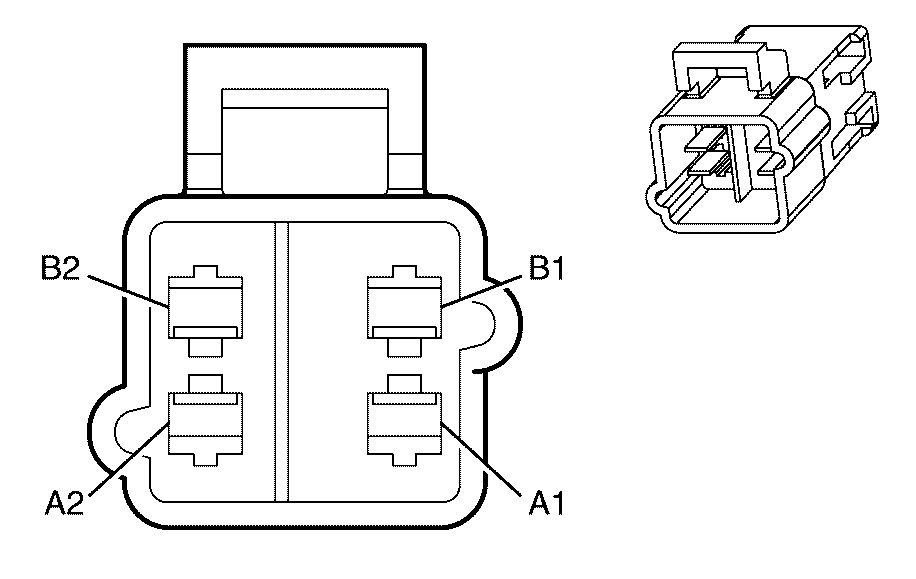
Connector Part Information
|
Terminal Part Information
|
Pin | Wire Color | Circuit No. | Function |
|---|---|---|---|
A1 | 0.3 BN/RD | 3021 | Steering Wheel Module - Stage1 - High Control |
A2 | 0.3 BN | 3020 | Steering Wheel Module - Stage1 - Low Control |
B1 | 0.3 WH | 3023 | Steering Wheel Module - Stage2 - High Control |
B2 | 0.3 PK | 3022 | Steering Wheel Module - Stage2 - Low Control |
Inflatable Restraint Steering Wheel Module X1
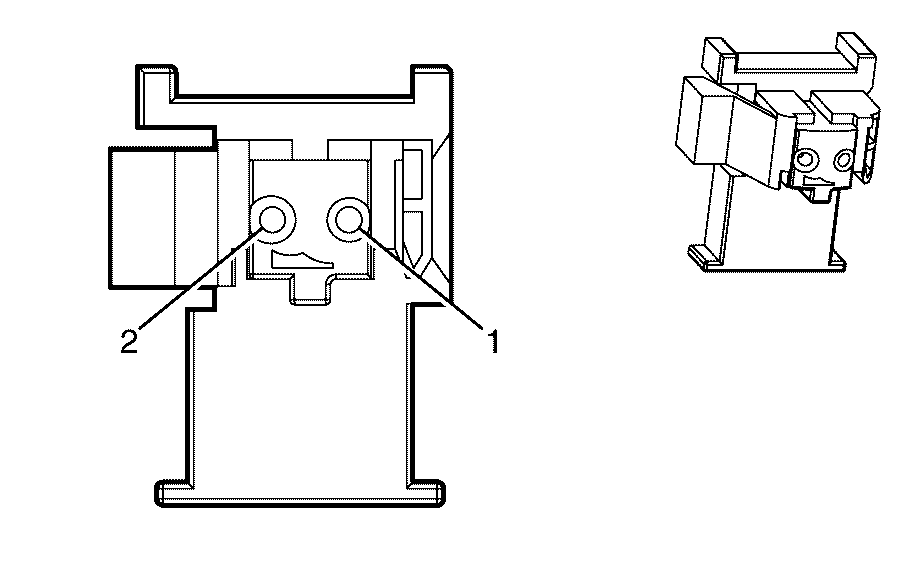
Connector Part Information
|
Terminal Part Information
|
Pin | Wire Color | Circuit No. | Function |
|---|---|---|---|
1 | 0.3 BN | 3020 | Steering Wheel Module - Stage1 - Low Control |
2 | 0.3 TN | 3021 | Steering Wheel Module - Stage1 - High Control |
Inflatable Restraint Steering Wheel Module X2

Connector Part Information
|
Terminal Part Information
|
Pin | Wire Color | Circuit No. | Function |
|---|---|---|---|
1 | 0.3 PK | 3022 | Steering Wheel Module - Stage2 - Low Control |
2 | 0.3 WH | 3023 | Steering Wheel Module - Stage2 - High Control |
Inside Rearview Mirror (ISRVM)
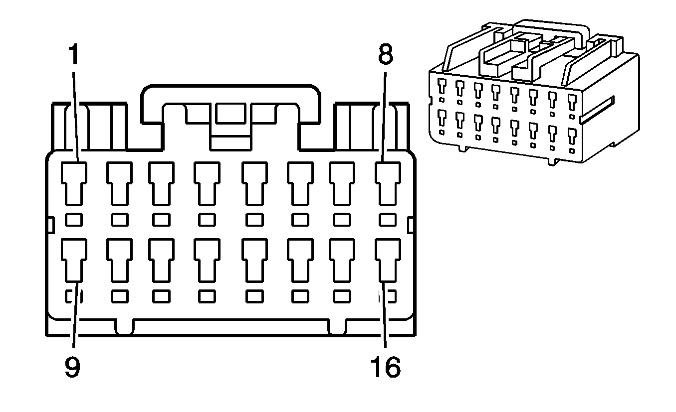
Connector Part Information
|
Terminal Part Information
|
Pin | Wire Color | Circuit No. | Function |
|---|---|---|---|
1-2 | -- | -- | Not Used |
3 | 0.3 BK/BN | 723 | I/P Module Disable Switch - Signal |
4 | 0.3 BK/PK | 353 | I/P Module Suppression Indicator Control |
5-7 | -- | -- | Not Used |
8 | 0.3 BK | 1450 | Ground |
9 | 0.5 L-GN | 24 | Backup Lamp Supply Voltage |
10 | -- | -- | Not Used |
11 | 0.3 D-GN/WH | 2514 | Keypad Signal |
12 | 0.3 L-GN/BK | 2515 | Keypad Supply Voltage |
13 | 0.5 PK/BU | 1339 | Ignition 1 Voltage |
14 | 0.3 YE/BK | 2516 | Keypad Green LED Signal |
15 | 0.3 BN/WH | 2517 | Keypad Red LED Signal |
16 | -- | -- | Not Used |
Instrument Panel Cluster (IPC)
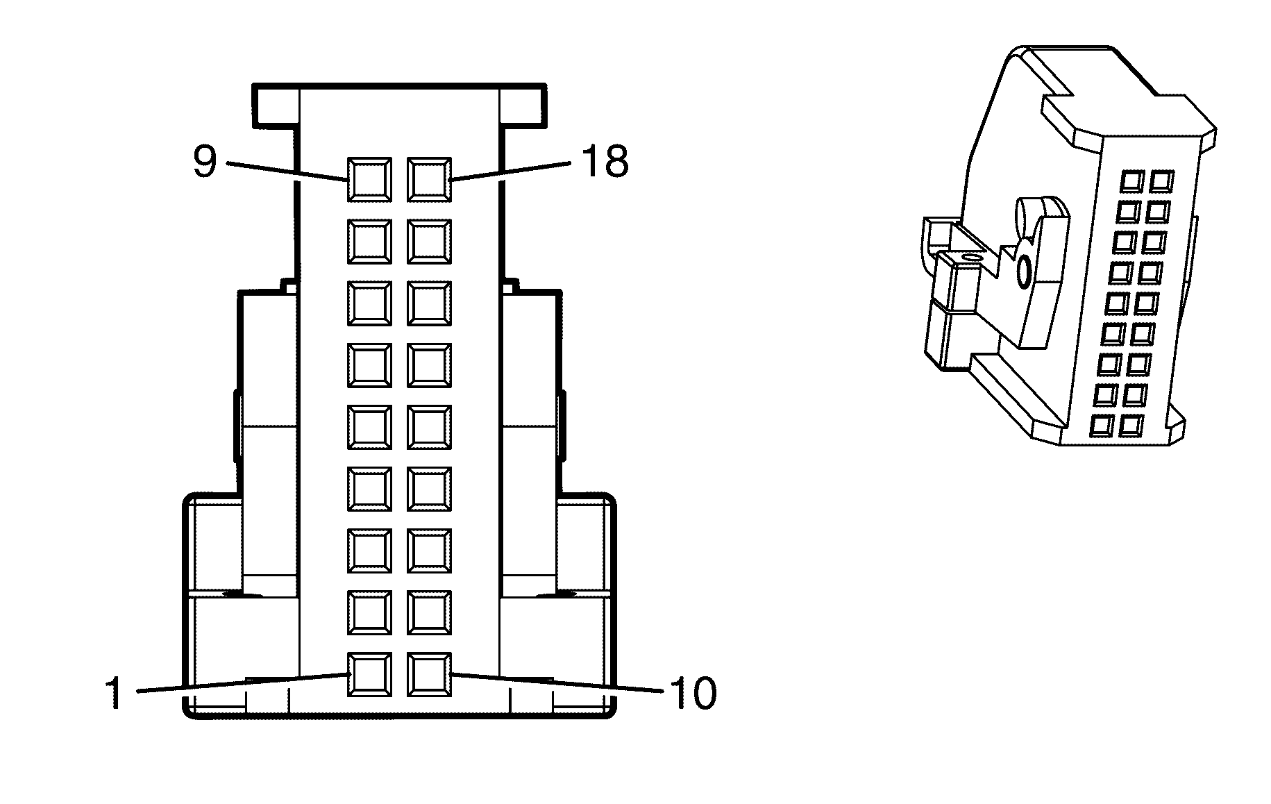
Connector Part Information
|
Terminal Part Information
|
Pin | Wire Color | Circuit No. | Function |
|---|---|---|---|
1 | 0.5 OG/WH | 1840 | Battery Positive Voltage |
2 | 0.3 GY | 728 | Security Indicator Control |
3 | -- | -- | Not Used |
4 | 0.3 BK/PK | 353 | I/P Module Suppression Indicator Control |
5 | -- | -- | Low Washer Fluid Indicator Signal |
6 | 0.3 BN | 7312 | Left Steering Wheel Scroll 1 |
7 | 0.3 GY/BU | 7367 | Right Steering Wheel Scroll 2 |
8 | 0.3 BN/GN | 7364 | Right Steering Wheel Scroll 1 |
9 | 0.5 BK | 850 | Ground |
10 | 0.3 PK | 3 | Ignition 1 Voltage |
11 | 0.3 BN/WH | 419 | MIL Control |
12 | 0.3 OG/BK | 5201 | Steering Wheel Controls Signal |
13 | 0.3 BN/WH | 33 | Brake Warning Indicator Control |
14 | -- | -- | Not Used |
15 | 0.35 D-GN | 9203 | Low Speed GMLAN Serial Data |
16 | 0.3 BK/BN | 723 | I/P Module Disable Switch - Signal |
17 | 0.3 L-BU | 7313 | Left Steering Wheel Scroll 2 |
18 | 0.3 BN/WH | 897 | Steering Wheel Controls Low Reference |
Intake Manifold Tuning (IMT) Solenoid Valve (LY7)
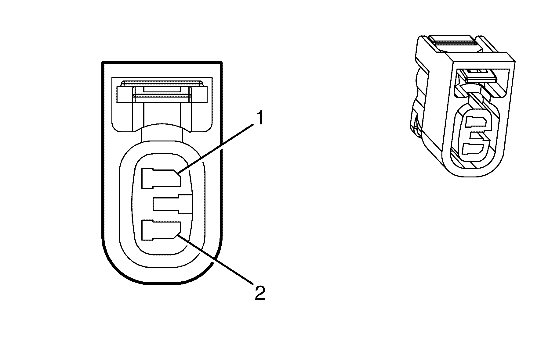
Connector Part Information
|
Terminal Part Information
|
Pin | Wire Color | Circuit No. | Function |
|---|---|---|---|
1 | 0.75 PK/BU | 5293 | Ignition 1 Voltage |
2 | 0.75 BN | 1997 | EVAP Canister Vent Solenoid Valve Low Reference |
Internal Mode Switch (IMS)
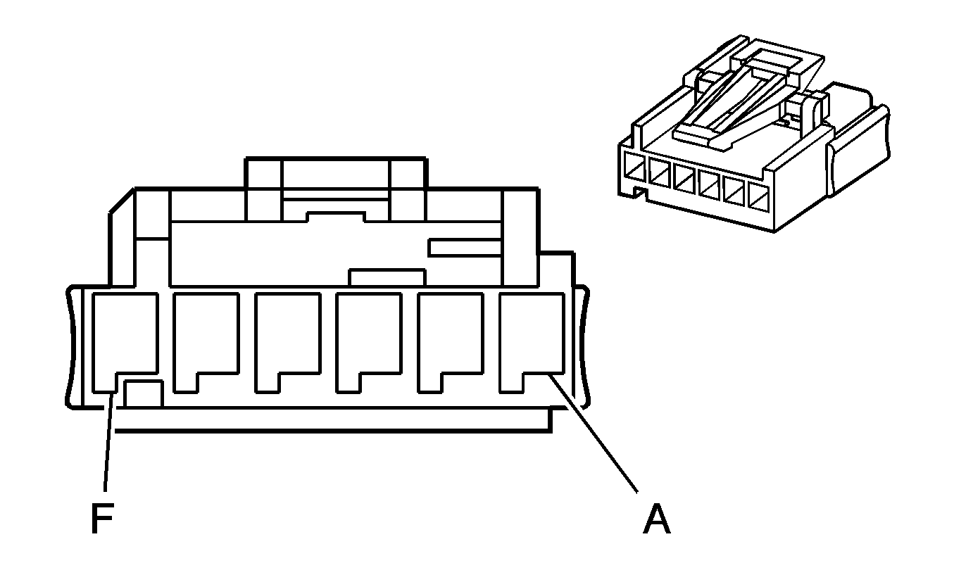
Connector Part Information
|
Terminal Part Information
|
Pin | Wire Color | Circuit No. | Function |
|---|---|---|---|
A | 0.5 BN | 1786 | Park/Neutral Signal |
B | 0.5 GY | 776 | Transmission Range Switch Signal P |
C | 0.5 BK | 772 | Transmission Range Switch Signal B |
D | 0.5 RD | 771 | Transmission Range Switch Signal A |
E | 0.5 D-BU | 773 | Transmission Range Switch Signal C |
F | 0.5 D-GN | 450 | Ground |
Knock Sensor (KS) 1 (LY7)

Connector Part Information
|
Terminal Part Information
|
Pin | Wire Color | Circuit No. | Function |
|---|---|---|---|
1 | 0.5 D-BU | 496 | Knock Sensor 1 Signal |
2 | 0.5 GY | 1716 | Low Reference Knock Sensor Signal Return |
Knock Sensor (KS) 1 (L76)
Connector Part Information
|
Terminal Part Information
|
Pin | Wire Color | Circuit No. | Function |
|---|---|---|---|
1 | 0.5 D-BU | 496 | Knock Sensor 1 Signal |
2 | 0.5 GY | 1716 | Low Reference Knock Sensor Signal Return |
Knock Sensor (KS) 2 (LY7)

Connector Part Information
|
Terminal Part Information
|
Pin | Wire Color | Circuit No. | Function |
|---|---|---|---|
1 | 0.5 L-BU | 1876 | Knock Sensor 2 Signal |
2 | 0.5 BN | 407 | Low Reference Knock Sensor Signal Return |
Knock Sensor (KS) 2 (L76)
Connector Part Information
|
Terminal Part Information
|
Pin | Wire Color | Circuit No. | Function |
|---|---|---|---|
1 | 0.5 L-BU | 1876 | Knock Sensor 2 Signal |
2 | 0.5 BN | 407 | Low Reference Knock Sensor Signal Return |
License Lamp - Left
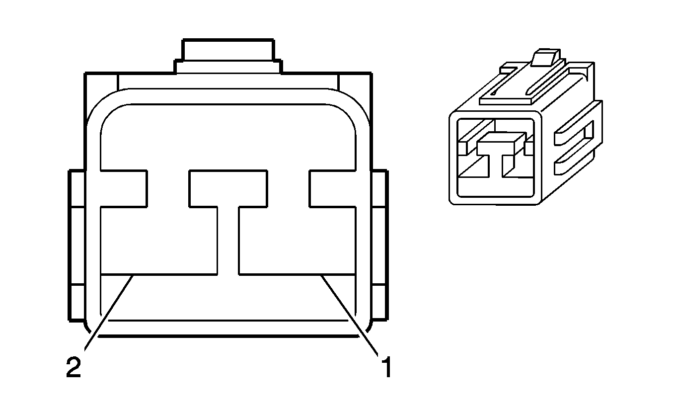
Connector Part Information
|
Terminal Part Information
|
Pin | Wire Color | Circuit No. | Function |
|---|---|---|---|
1 | 0.5 BN/WH | 309 | Right Park Lamp Supply Voltage |
2 | 0.5 BK | 1350 | Ground |
License Lamp - Right

Connector Part Information
|
Terminal Part Information
|
Pin | Wire Color | Circuit No. | Function |
|---|---|---|---|
1 | 0.5 BN/WH | 309 | Right Park Lamp Supply Voltage |
2 | 0.5 BK | 1350 | Ground |
Manifold Absolute Pressure (MAP) Sensor (L76)
Connector Part Information
|
Terminal Part Information
|
Pin | Wire Color | Circuit No. | Function |
|---|---|---|---|
1 | 0.5 GY | 2704 | 5-Volt Reference |
2 | 0.5 OG/BK | 469 | Low Reference |
3 | 0.5 L-GN | 432 | MAP Sensor Signal |
Mass Air Flow (MAF)/Intake Air Temperature (IAT) Sensor
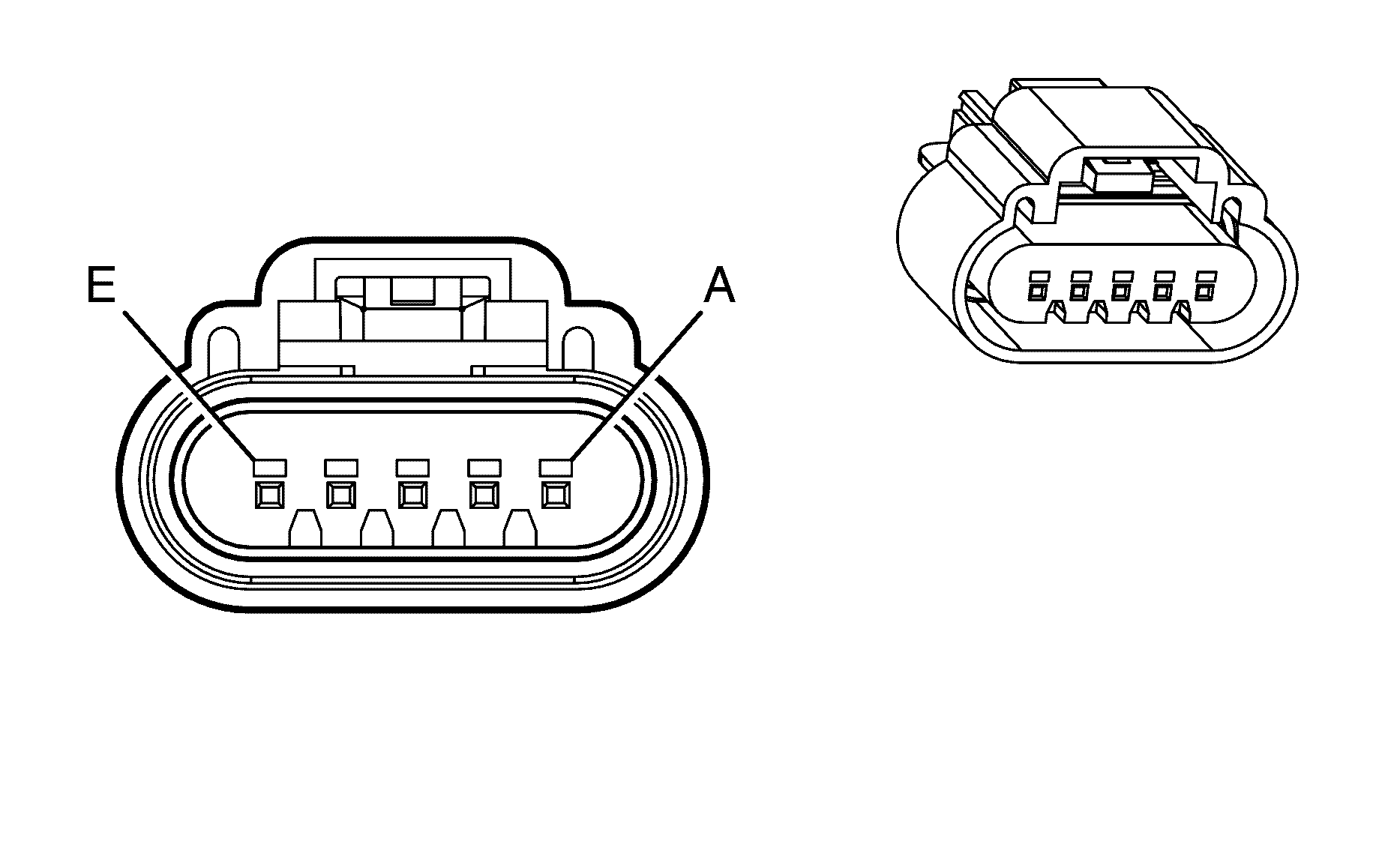
Connector Part Information
|
Terminal Part Information
|
Pin | Wire Color | Circuit No. | Function |
|---|---|---|---|
A | 0.5 YE | 492 | MAF Sensor Signal |
B | 0.5 PK | 439 | Ignition 1 Voltage |
C | 0.5 BK | 450 | Ground |
D | 0.5 BN/RD | 472 | IAT Sensor Signal |
E | 0.5 BN/WH | 2760 | Low Reference |
Mode Actuator

Connector Part Information
|
Terminal Part Information
|
Pin | Wire Color | Circuit No. | Function |
|---|---|---|---|
1 | 0.5 GY | 1791 | Low Reference |
2 | -- | -- | Not Used |
3 | 0.5 YE | 598 | 5-Volt Reference |
4 | -- | -- | Not Used |
5 | 0.5 RD | 2275 | Mode Door Control B |
6 | 0.5 YE/BK | 119 | Mode Door Control |
7 | 0.5 PK | 2273 | Mode Door Control |
Mode Actuator - Auxiliary

Connector Part Information
|
Terminal Part Information
|
Pin | Wire Color | Circuit No. | Function |
|---|---|---|---|
1 | 0.5 GY | 1791 | Low Reference |
2 | -- | -- | Not Used |
3 | 0.5 YE | 598 | 5-Volt Reference |
4 | -- | -- | Not Used |
5 | 0.5 BN/RD | 2275 | Mode Door Control B |
6 | 0.5 D-BU | 119 | Mode Door Control |
7 | 0.5 OG | 454 | Mode Door Control |
Multifunction Switch - Center Console X1
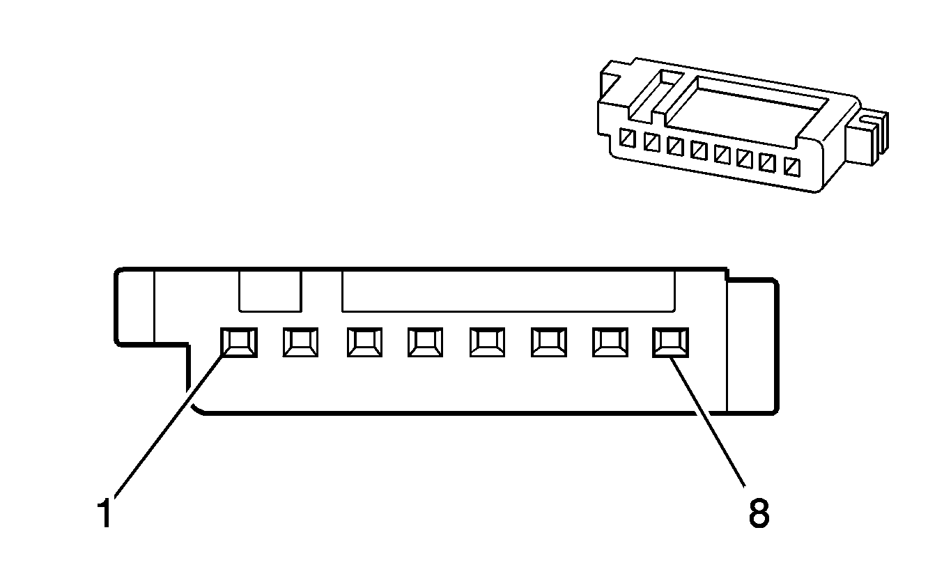
Connector Part Information
|
Terminal Part Information
|
Pin | Wire Color | Circuit No. | Function |
|---|---|---|---|
1 | 0.3 YE | 6817 | LED Backlight Dimming Control |
2 | 0.3 BK | 850 | Ground |
3 | 0.3 PK | 1501 | Driver Heated Seat High/Low Signal (KA1) |
4 | 0.3 D-GN | 1661 | Driver Heated Seat High Temperature Indicator Control (KA1) |
5 | 0.3 WH/BK | 6177 | Passenger Heated Seat Intermediate Signal (KA1) |
6 | 0.3 L-BU | 1662 | Driver Heated Seat Low Temperature Indicator Control (KA1) |
7 | -- | -- | Not Used |
8 | 0.3 BN/OG | 1571 | Object Detection Disable Signal |
Multifunction Switch - Center Console X2 (KA1)
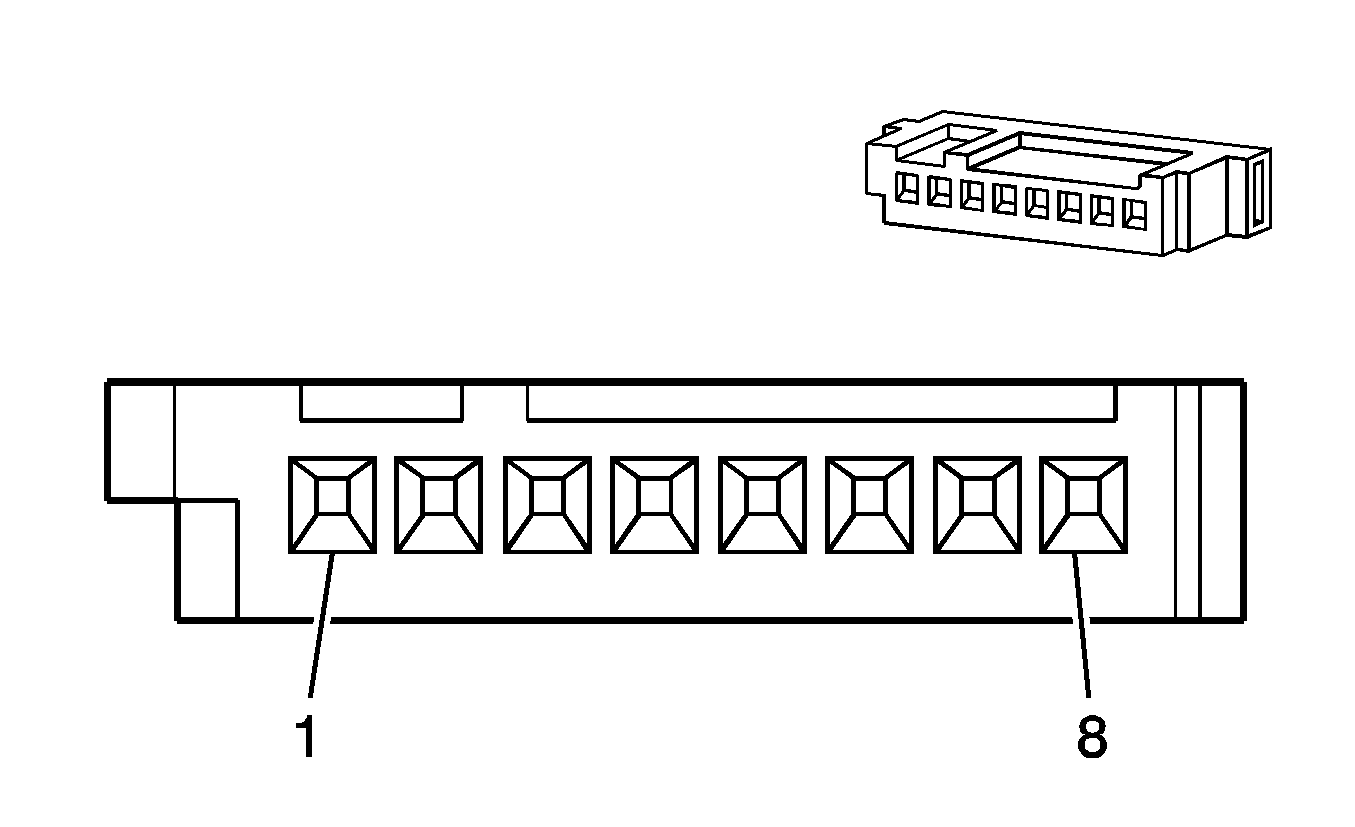
Connector Part Information
|
Terminal Part Information
|
Pin | Wire Color | Circuit No. | Function |
|---|---|---|---|
1 | 0.5 PK/BU | 1339 | Ignition 1 Voltage |
2 | 0.3 YE | 1685 | Passenger Heated Seat High Temperature Indicator Control |
3 | 0.3 WH/BK | 6185 | Passenger Heated Seat Intermediate Signal |
4 | 0.3 BN | 1686 | Passenger Heated Seat Low Temperature Indicator Control |
5 | 0.3 PU/WH | 6816 | Heated Seat Supply Voltage |
6 | 0.3 PK/BK | 1503 | Passenger Heated Seat High/Low Signal |
7 | -- | -- | Not Used |
8 | 0.5 BK | 850 | Ground |
Outside Rearview Mirror - Driver
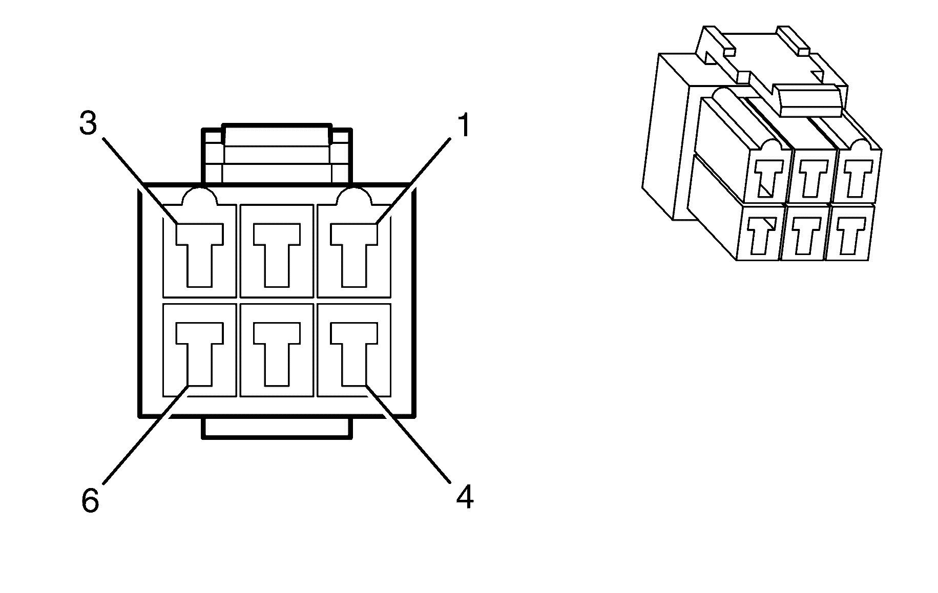
Connector Part Information
|
Terminal Part Information
|
Pin | Wire Color | Circuit No. | Function |
|---|---|---|---|
1 | 0.5 WH/BU | 7391 | Power Window Switch Right and Up |
2 | 0.5 WH/BK | 81 | Driver Mirror Motor Right Control |
3 | -- | -- | Not Used |
4 | 0.5 L-GN/BK | 89 | Driver Mirror Motor Down Control |
5-6 | -- | -- | Not Used |
Outside Rearview Mirror - Passenger

Connector Part Information
|
Terminal Part Information
|
Pin | Wire Color | Circuit No. | Function |
|---|---|---|---|
1 | 0.5 WH/BU | 7391 | Power Window Switch Right and Up |
2 | 0.5 OG/WH | 881 | Passenger Mirror Motor Right Control |
3 | -- | -- | Not Used |
4 | 0.5 PU/WH | 889 | Passenger Mirror Motor Down Control |
5-6 | -- | -- | Not Used |
Park Brake Switch
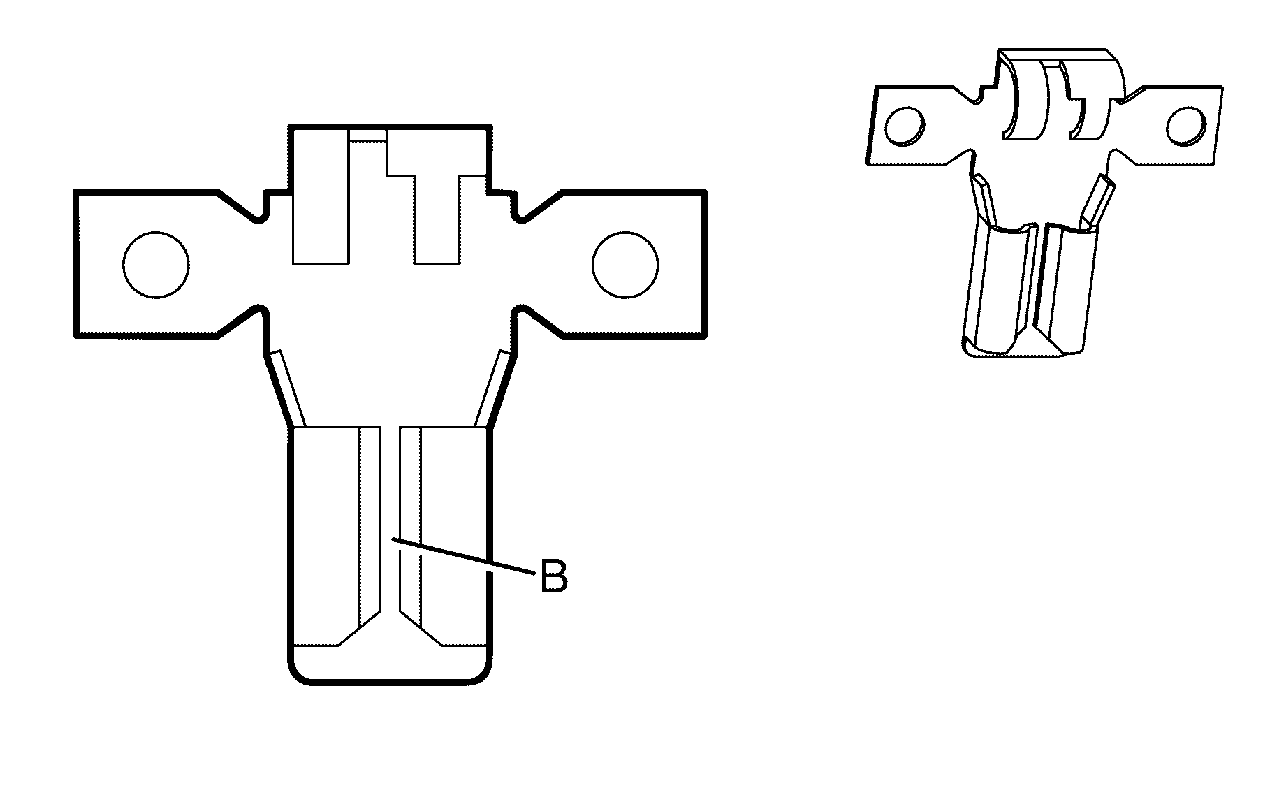
Connector Part Information
|
Terminal Part Information
|
Pin | Wire Color | Circuit No. | Function |
|---|---|---|---|
B | 0.85 OG/BK | 233 | Park Brake Switch Signal |
Pressure Control (PC) Solenoid Valve

Connector Part Information
|
Terminal Part Information
|
Pin | Wire Color | Circuit No. | Function |
|---|---|---|---|
A | 0.5 D-GN | 1228 | PC Solenoid Valve High Control |
B | 0.5 WH | 1229 | PC Solenoid Valve Low Control |
Radio X1
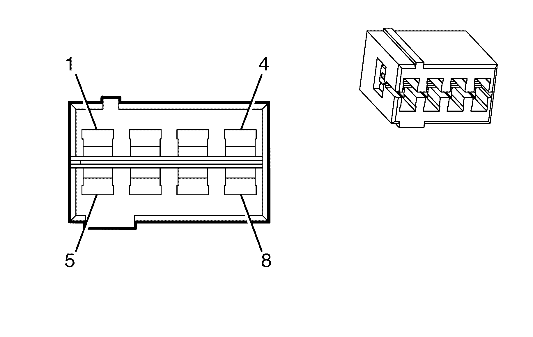
Connector Part Information
|
Terminal Part Information
|
Pin | Wire Color | Circuit No. | Function |
|---|---|---|---|
1 | 0.5 L-BU | 115 | Right Rear Speaker Output (-) |
2 | 0.5 D-GN | 117 | Right Front Speaker Output (-) |
3 | 0.5 GY | 118 | Left Front Speaker Output (-) |
4 | 0.5 YE/RD | 116 | Left Rear Speaker Output (-) |
5 | 0.5 D-BU | 46 | Right Rear Speaker Output (+) |
6 | 0.5 L-GN | 200 | Right Front Speaker Output (+) |
7 | 0.5 BN | 201 | Left Front Speaker Output (+) |
8 | 0.5 BN | 199 | Left Rear Speaker Output (+) |
Radio X2
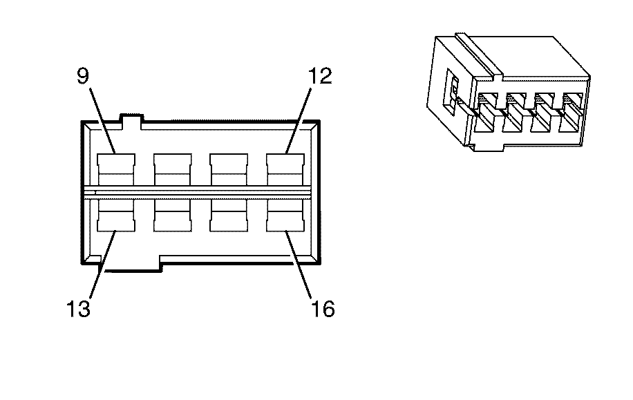
Connector Part Information
|
Terminal Part Information
|
Pin | Wire Color | Circuit No. | Function |
|---|---|---|---|
9 | 0.5 L-BU | 1860 | Front Center Speaker Output (+) (UWP) |
10 | 0.85 OG/BU | 4340 | Battery Positive Voltage |
11 | -- | -- | Not Used |
12 | 1.25 BK | 1050 | Ground |
13 | 0.5 OG | 1860 | Front Center Speaker Output (+) (UWP) |
14 | 0.85 OG/BU | 4340 | Battery Positive Voltage |
15 | 0.85 OG/BU | 4340 | Battery Positive Voltage |
16 | 1.25 BK | 1050 | Ground |
Radio X4
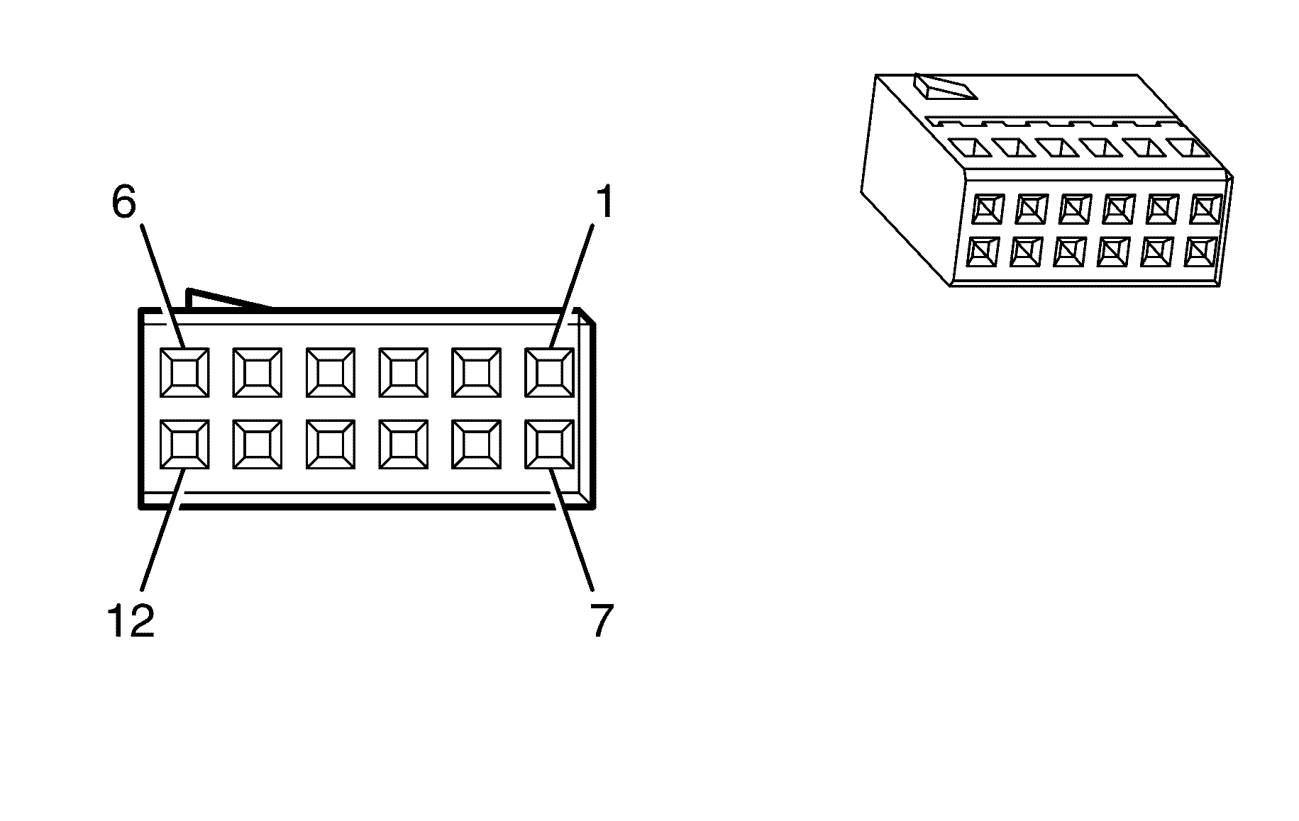
Connector Part Information
|
Terminal Part Information
|
Pin | Wire Color | Circuit No. | Function |
|---|---|---|---|
1 | 0.3 L-BU | 659 | Telephone Audio Signal (-) |
2 | 0.5 GY | 388 | Remote Radio Right Audio Signal |
3 | 0.5 BN/WH | 372 | Remote Radio Audio Output (-) |
4 | 0.35 BK | 6131 | Battery Positive Voltage |
5 | 0.3 WH | 700 | Telephone Audio Signal Mute |
6 | 0.35 L-GN | 9202 | Low Speed GMLAN Serial Data |
7 | 0.3 D-BU | 658 | Telephone Audio Signal (+) |
8 | 0.5 GY/BK | 7008 | Right Radio Audio Output |
9 | 0.5 D-GN | 7007 | Left Radio Audio Output |
10-12 | -- | -- | Not Used |
Rear Compartment Courtesy Lamp X1
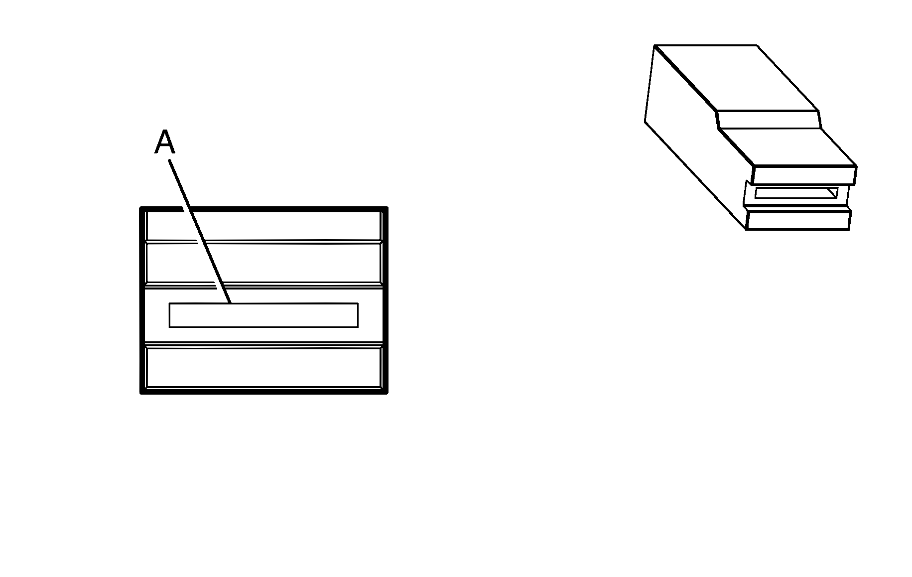
Connector Part Information
|
Terminal Part Information
|
Pin | Wire Color | Circuit No. | Function |
|---|---|---|---|
A | 0.85 OG | 1732 | Courtesy Lamps Supply Voltage |
Rear Compartment Courtesy Lamp X2

Connector Part Information
|
Terminal Part Information
|
Pin | Wire Color | Circuit No. | Function |
|---|---|---|---|
A | 0.5 D-BU | 737 | Rear Compartment Lamp Control |
Rear Compartment Lid Latch
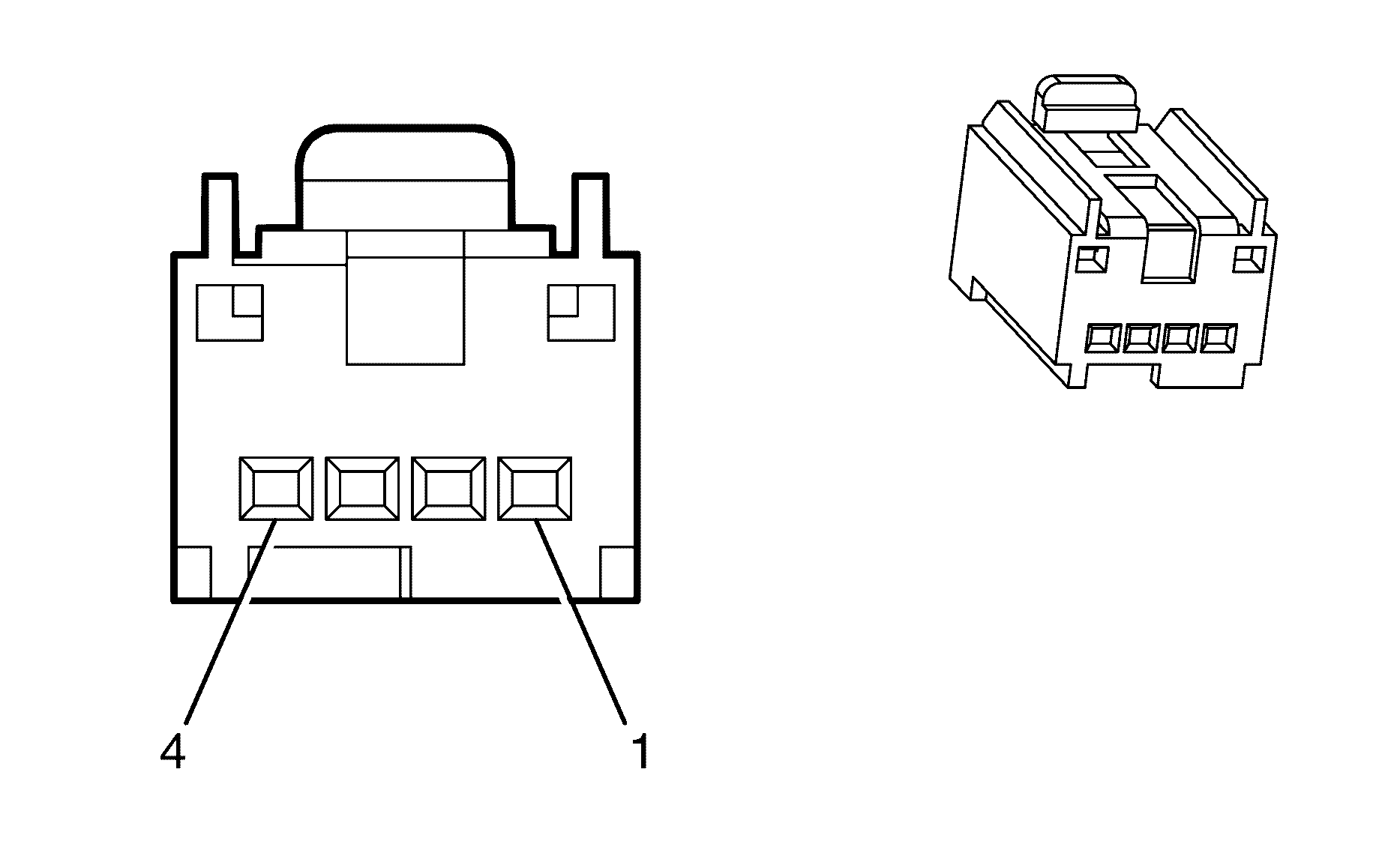
Connector Part Information
|
Terminal Part Information
|
Pin | Wire Color | Circuit No. | Function |
|---|---|---|---|
1 | 0.3 OG/BK | 744 | Rear Compartment Lid Ajar Switch Signal |
2 | 0.5 D-BU | 737 | Rear Compartment Lamp Control |
3 | 0.85 BN/WH | 56 | Rear Compartment Lid Release Actuator |
4 | 0.85 BK | 1850 | Ground |
Rear Compartment Lid Release Switch
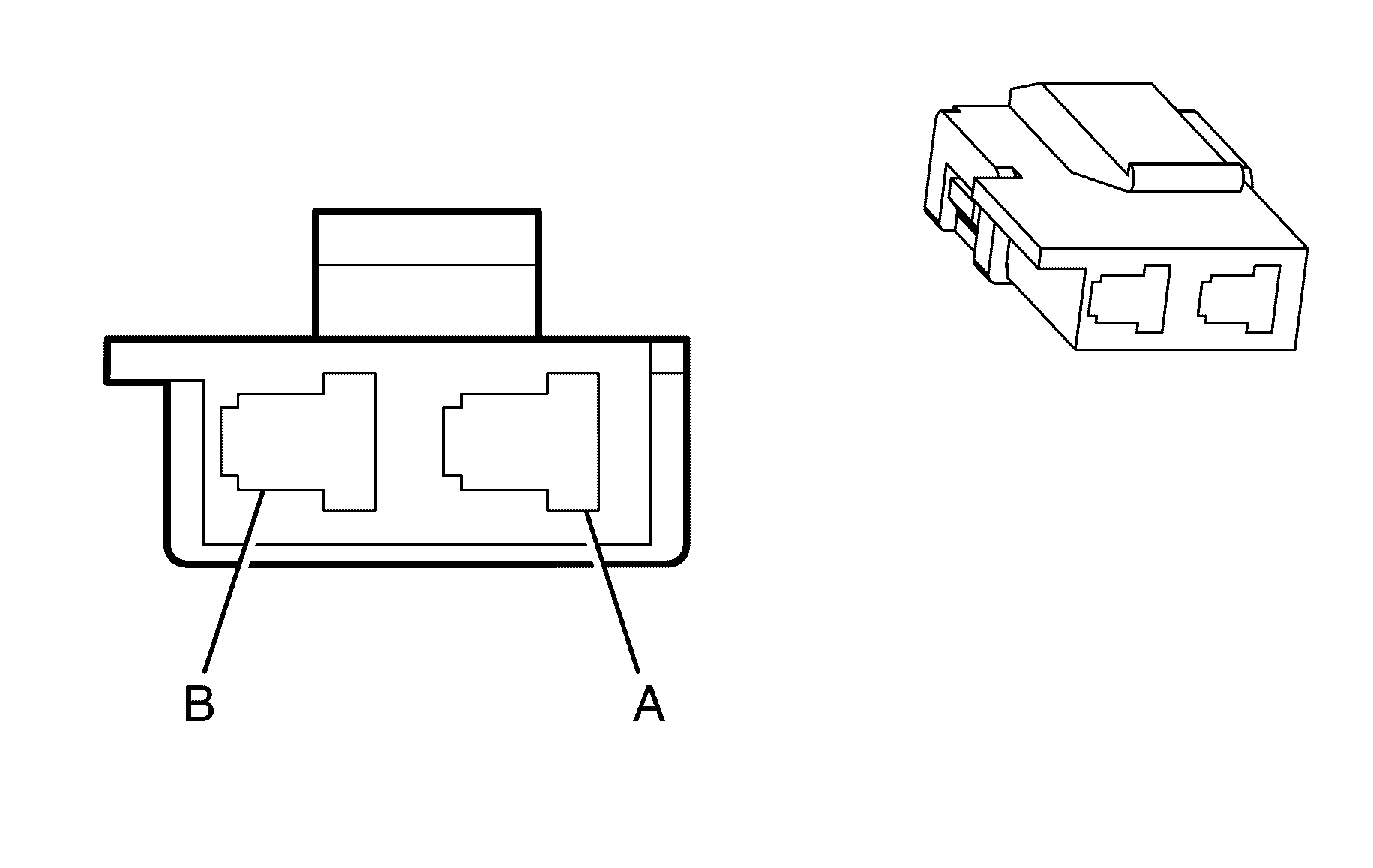
Connector Part Information
|
Terminal Part Information
|
Pin | Wire Color | Circuit No. | Function |
|---|---|---|---|
A | 0.5 D-BU | 6189 | Rear Compartment Relay Switch |
B | 0.5 BK | 1450 | Ground |
Rear Object Sensor Control Module Connector
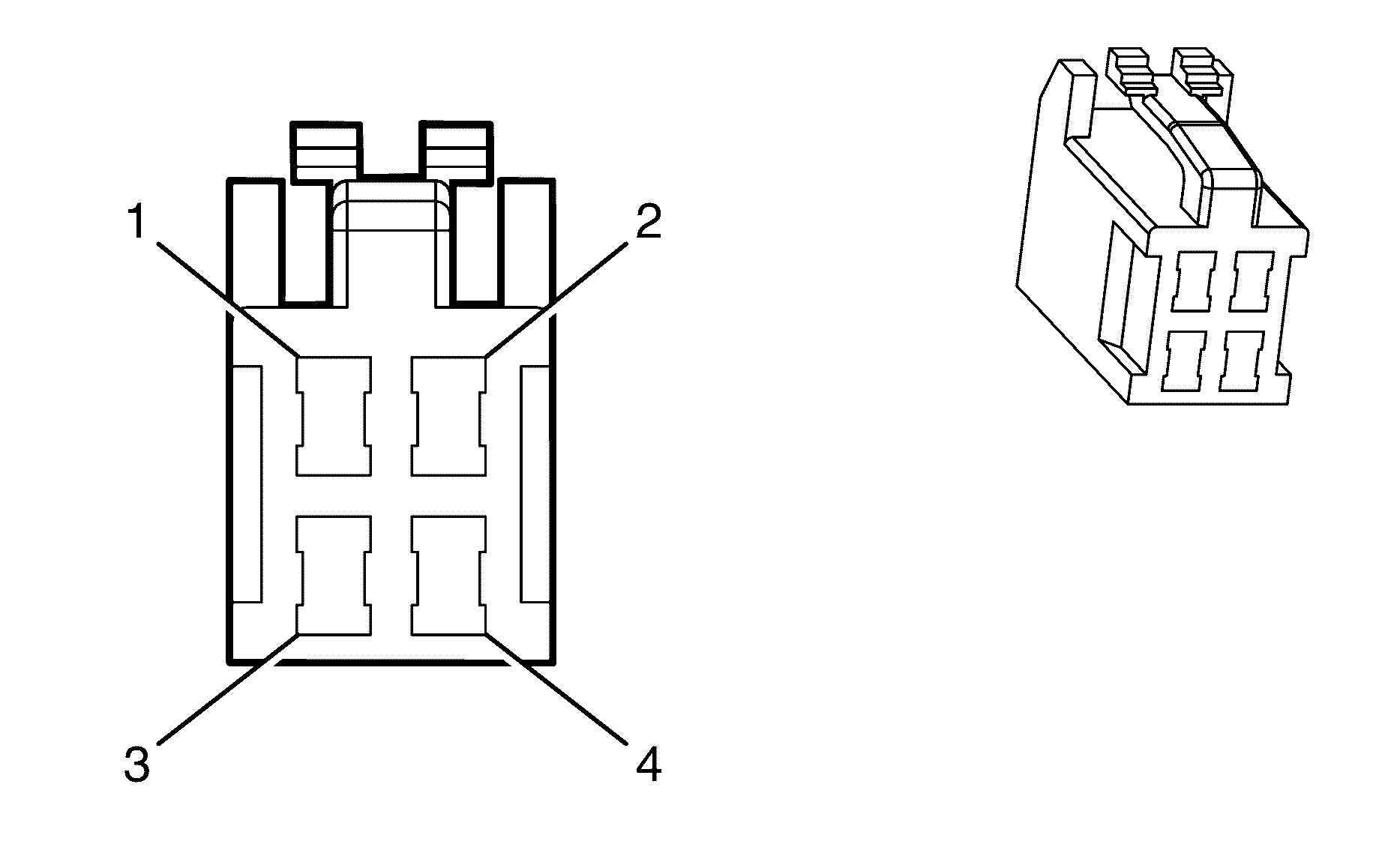
Connector Part Information
|
Terminal Part Information
|
Pin | Wire Color | Circuit No. | Function |
|---|---|---|---|
1 | 0.5 BN/BU | 343 | Not Used |
2 | 0.85 L-GN | 24 | Not Used |
3 | 0.5 BK | 1650 | Not Used |
4 | -- | -- | Not Used |
Rear Window Defogger Grid X1

Connector Part Information
|
Terminal Part Information
|
Pin | Wire Color | Circuit No. | Function |
|---|---|---|---|
A | 3 PU | 293 | Rear Defog Element Supply Voltage |
Rear Window Defogger Grid X2

Connector Part Information
|
Terminal Part Information
|
Pin | Wire Color | Circuit No. | Function |
|---|---|---|---|
A | 3 BK | 1650 | Ground |
Recirculation Actuator

Connector Part Information
|
Terminal Part Information
|
Pin | Wire Color | Circuit No. | Function |
|---|---|---|---|
1 | 0.5 YE | 598 | 5-Volt Reference |
2 | -- | -- | Not Used |
3 | 0.5 GY | 1791 | Low Referencel |
4 | -- | -- | Not Used |
5 | 0.5 WH/OG | 1838 | Recirculation Door Position Signal |
6 | 0.5 PU | 2274 | Recirculation Door Control Circuit |
7 | 0.5 WH/BU | 1614 | Recirculation Door Control |
Remote Control Door Lock Receiver (RCDLR)
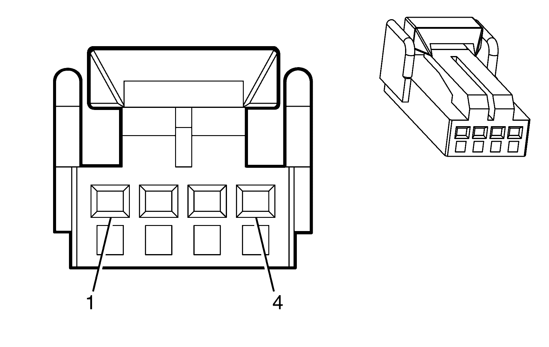
Connector Part Information
|
Terminal Part Information
|
Pin | Wire Color | Circuit No. | Function |
|---|---|---|---|
1 | 0.5 OG/WH | 1840 | Battery Positive Voltage |
2 | 0.35 D-GN | 5060 | Low Speed GMLAN Serial Data |
3 | -- | -- | Not Used |
4 | 0.5 BK | 1650 | Ground |
Seat Adjuster Switch - Driver
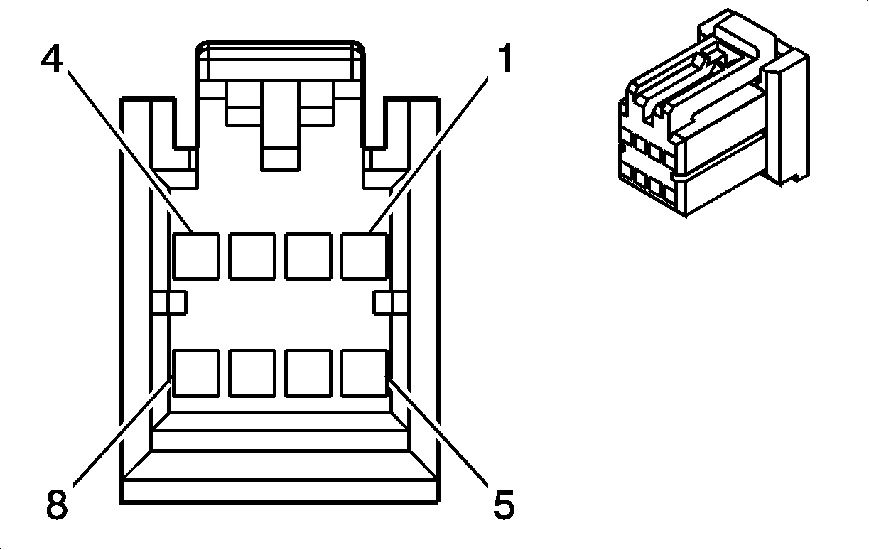
Connector Part Information
|
Terminal Part Information
|
Pin | Wire Color | Circuit No. | Function |
|---|---|---|---|
1 | 2 BN | 282 | Driver Seat Rear Vertical Motor Up Control |
2 | 2 D-BU | 287 | Driver Seat Front Vertical Motor Down Control |
3 | 2 D-GN/YE | 286 | Driver Seat Front Vertical Motor Up Control |
4 | 2 D-BU/RD | 283 | Driver Seat Rear Vertical Motor Down Control |
5 | 2 GY/RD | 284 | Driver Seat Horizontal Motor Rearward Control (AJ6) |
6 | 2 RD | 1140 | Battery Positive Voltage |
7 | 2 BK | 2050 | Ground |
8 | 2 GY | 285 | Driver Seat Horizontal Motor Forward Control (AJ6) |
Seat Adjuster Switch - Passenger

Connector Part Information
|
Terminal Part Information
|
Pin | Wire Color | Circuit No. | Function |
|---|---|---|---|
1 | 2 D-BU/RD | 289 | Passenger Seat Rear Vertical Motor Down Control |
2 | 2 D-GN/YE | 297 | Passenger Seat Front Vertical Motor Up Control |
3 | 2 D-BU | 298 | Passenger Seat Front Vertical Motor Down Control |
4 | 2 BN | 288 | Passenger Seat Rear Vertical Motor Up Control |
5 | 2 GY/RD | 290 | Passenger Seat Horizontal Motor Rearward Control (AQ5) |
6 | 2 RD | 1140 | Battery Positive Voltage |
7 | 2 BK | 1350 | Ground |
8 | 2 GY | 296 | Passenger Seat Horizontal Motor Forward Control (AQ5) |
Seat Belt Buckle Pretensioner - Driver
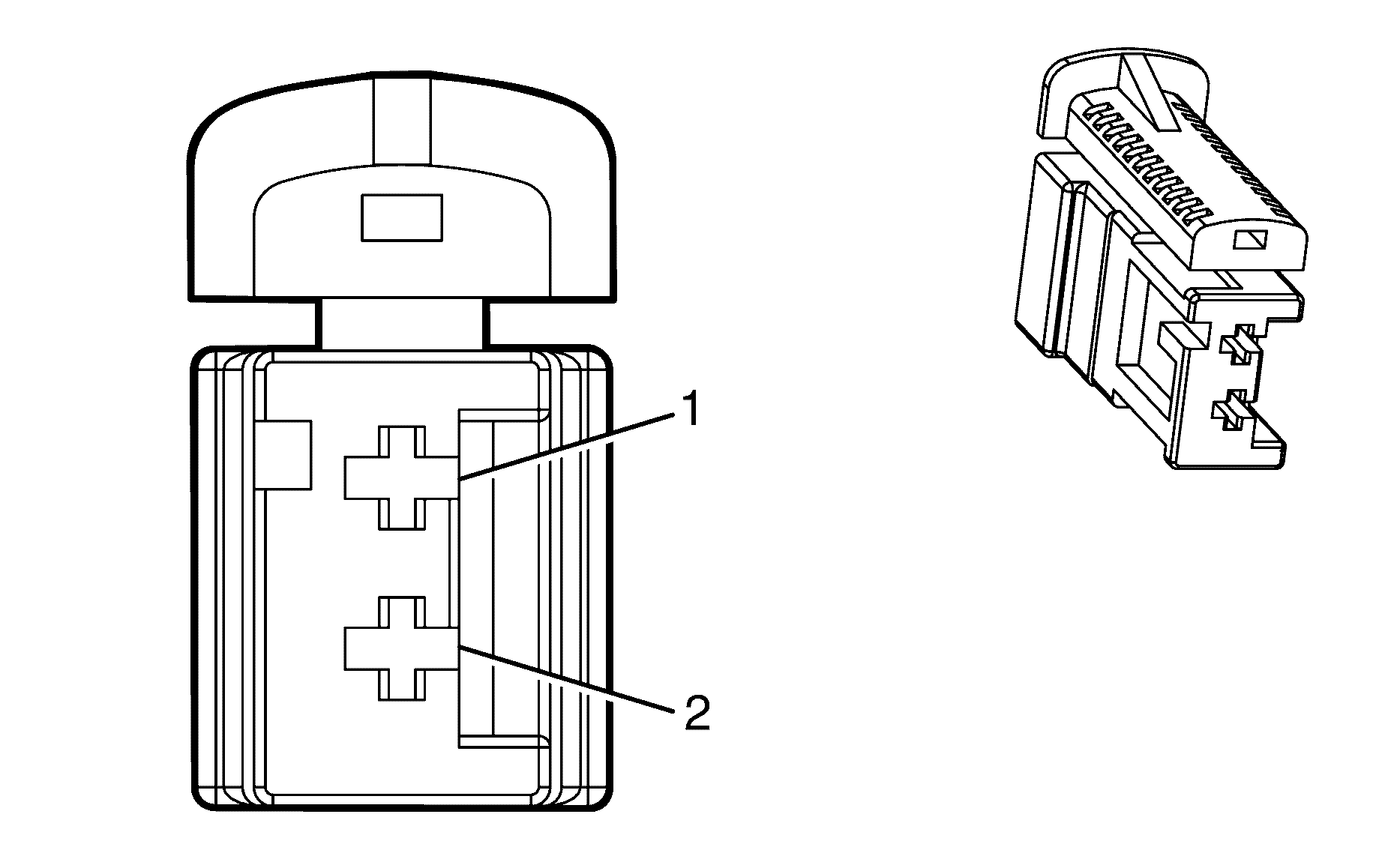
Connector Part Information
|
Terminal Part Information
|
Pin | Wire Color | Circuit No. | Function |
|---|---|---|---|
1 | 0.3 BK/WH | 2118 | Seat Belt Pretensioner - Left - High Control |
2 | 0.3 OG/BK | 2119 | Seat Belt Pretensioner - Left - Low Control |
Seat Belt Retractor Pretensioner - Driver
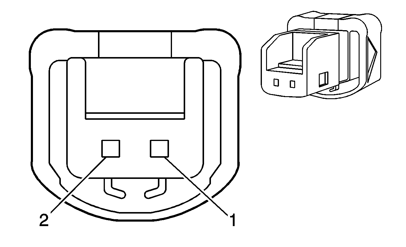
Connector Part Information
|
Terminal Part Information
|
Pin | Wire Color | Circuit No. | Function |
|---|---|---|---|
1 | 0.3 WH | 7206 | Driver Seat Belt Pretensioner Retractor - Low Control |
2 | 0.3 OG/GN | 7203 | Driver Seat Belt Pretensioner Retractor - High Control |
Seat Belt Buckle Pretensioner - Passenger

Connector Part Information
|
Terminal Part Information
|
Pin | Wire Color | Circuit No. | Function |
|---|---|---|---|
1 | 0.3 L-GN | 2116 | Seat Belt Pretensioner - Right - High Control |
2 | 0.3 OG | 2117 | Seat Belt Pretensioner - Right - Low Control |
Seat Belt Retractor Pretensioner - Passenger

Connector Part Information
|
Terminal Part Information
|
Pin | Wire Color | Circuit No. | Function |
|---|---|---|---|
1 | 0.3 PU/GN | 7205 | Passenger Seat Belt Pretensioner Retractor - High Control |
2 | 0.3 OG/BU | 7204 | Passenger Seat Belt Pretensioner Retractor - Low Control |
Seat Belt Switch - Driver
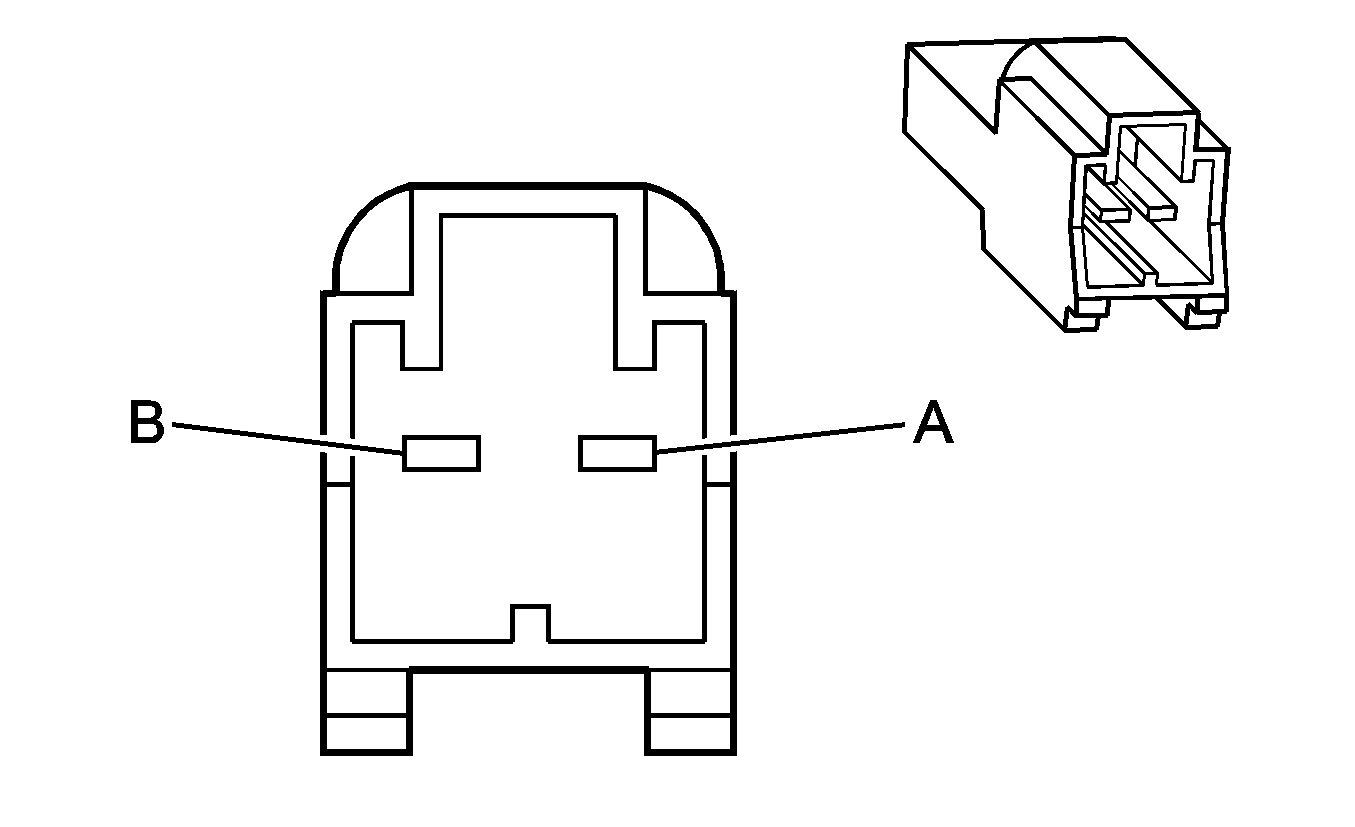
Connector Part Information
|
Terminal Part Information
|
Pin | Wire Color | Circuit No. | Function |
|---|---|---|---|
A | 0.3 BK/WH | 238 | Seat Belt Switch - Right Front |
B | 0.3 BK | 1363 | Seat Belt Switch - Left - Low Reference |
Seat Belt Switch - Passenger

Connector Part Information
|
Terminal Part Information
|
Pin | Wire Color | Circuit No. | Function |
|---|---|---|---|
A | 0.3 BK/WH | 1362 | Seat Belt Switch - Right - Signal |
B | 0.3 BK | 1363 | Seat Belt Switch - Left - Low Reference |
Seat Front Vertical Motor - Driver
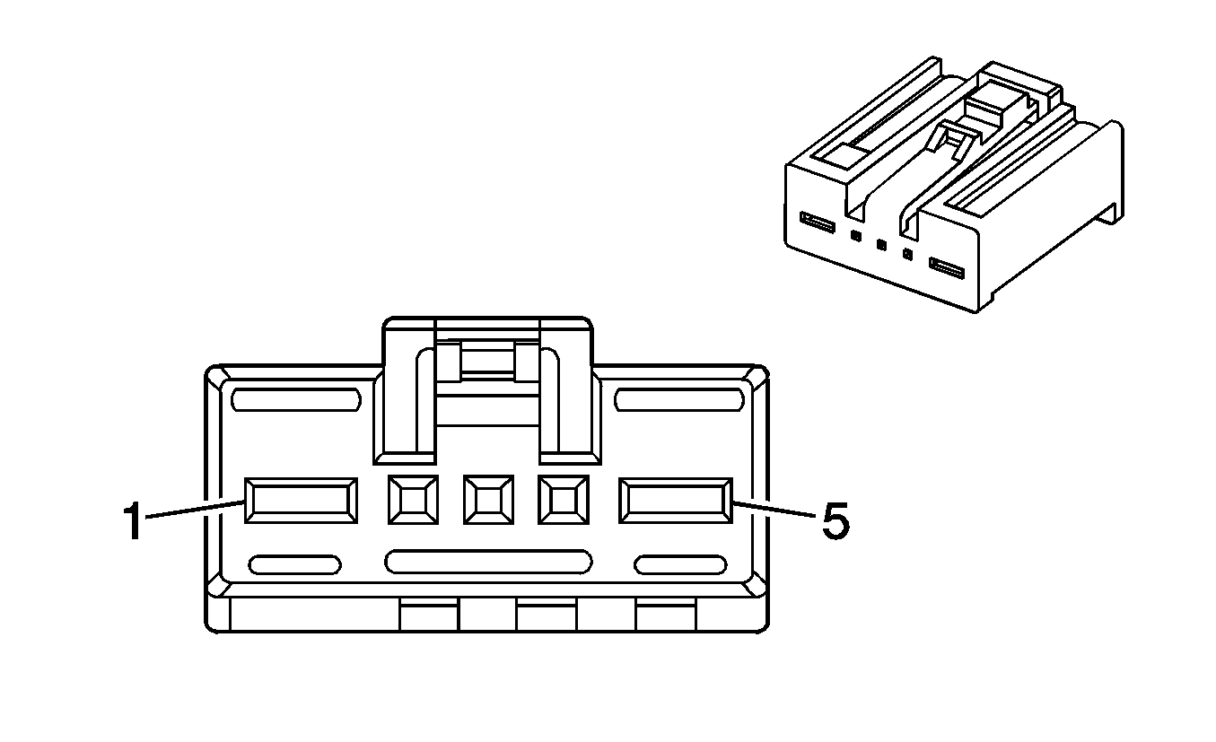
Connector Part Information
|
Terminal Part Information
|
Pin | Wire Color | Circuit No. | Function |
|---|---|---|---|
1 | 2 D-GN/YE | 286 | Driver Seat Front Vertical Motor Up Control |
2-4 | -- | -- | Not Used |
5 | 2 D-BU | 287 | Driver Seat Front Vertical Motor Down Control |
Seat Front Vertical Motor - Passenger

Connector Part Information
|
Terminal Part Information
|
Pin | Wire Color | Circuit No. | Function |
|---|---|---|---|
1 | 2 D-GN/YE | 297 | Passenger Seat Front Vertical Motor Up Control |
2-4 | -- | -- | Not Used |
5 | 2 D-BU | 298 | Passenger Seat Front Vertical Motor Down Control |
Seat Horizontal Motor - Driver (AJ6)
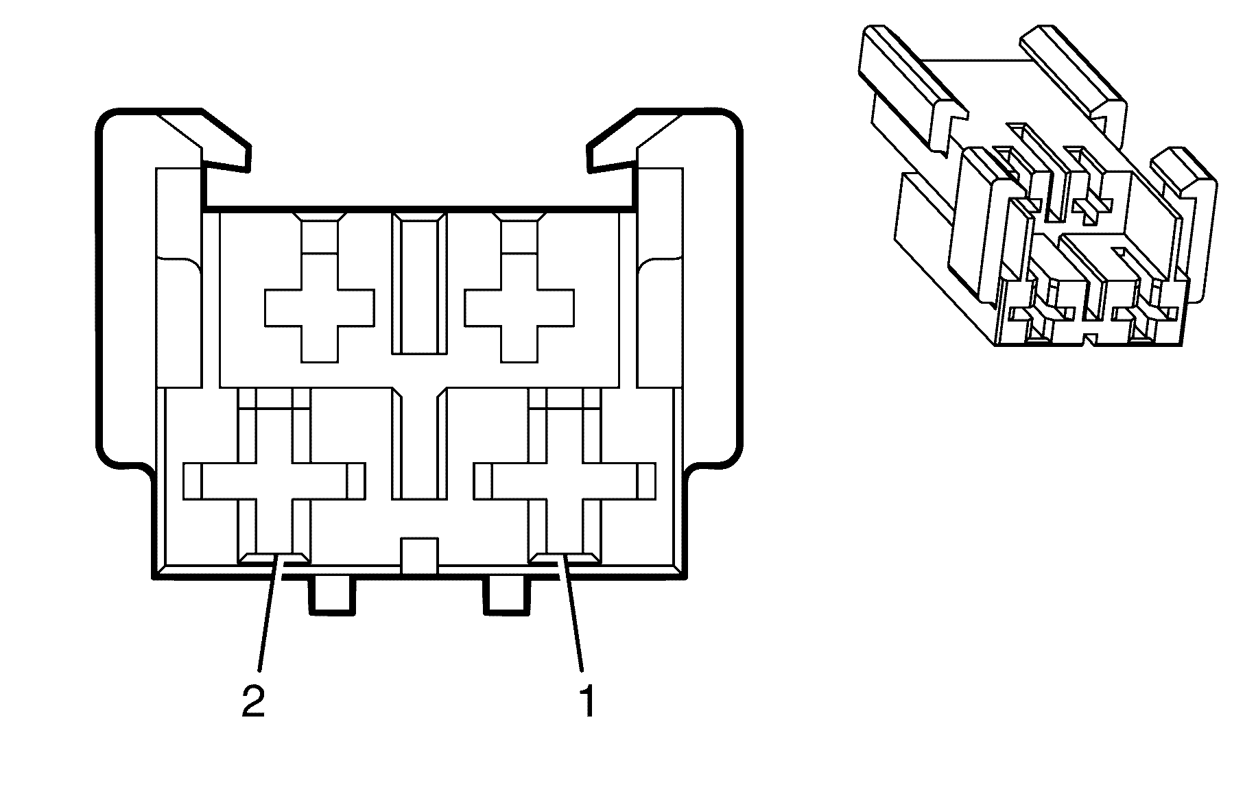
Connector Part Information
|
Terminal Part Information
|
Pin | Wire Color | Circuit No. | Function |
|---|---|---|---|
1 | 2 GY | 285 | Driver Seat Horizontal Motor Forward Control |
2 | 2 GY/RD | 284 | Driver Seat Horizontal Motor Rearward Control |
Seat Horizontal Motor - Passenger (AQ5)

Connector Part Information
|
Terminal Part Information
|
Pin | Wire Color | Circuit No. | Function |
|---|---|---|---|
1 | 2 GY | 296 | Passenger Seat Horizontal Motor Forward Control |
2 | 2 GY/RD | 290 | Passenger Seat Horizontal Motor Rearward Control |
Seat Rear Vertical Motor - Driver

Connector Part Information
|
Terminal Part Information
|
Pin | Wire Color | Circuit No. | Function |
|---|---|---|---|
1 | 2 BN | 282 | Driver Seat Rear Vertical Motor Up Control |
2-4 | -- | -- | Not Used |
5 | 2 D-BU/RD | 283 | Driver Seat Rear Vertical Motor Down Control |
Seat Rear Vertical Motor - Passenger

Connector Part Information
|
Terminal Part Information
|
Pin | Wire Color | Circuit No. | Function |
|---|---|---|---|
1 | 2 BN | 288 | Passenger Seat Rear Vertical Motor Up Control |
2-4 | -- | -- | Not Used |
5 | 2 D-BU/RD | 289 | Passenger Seat Rear Vertical Motor Down Control |
Side Marker Lamp - Left Front
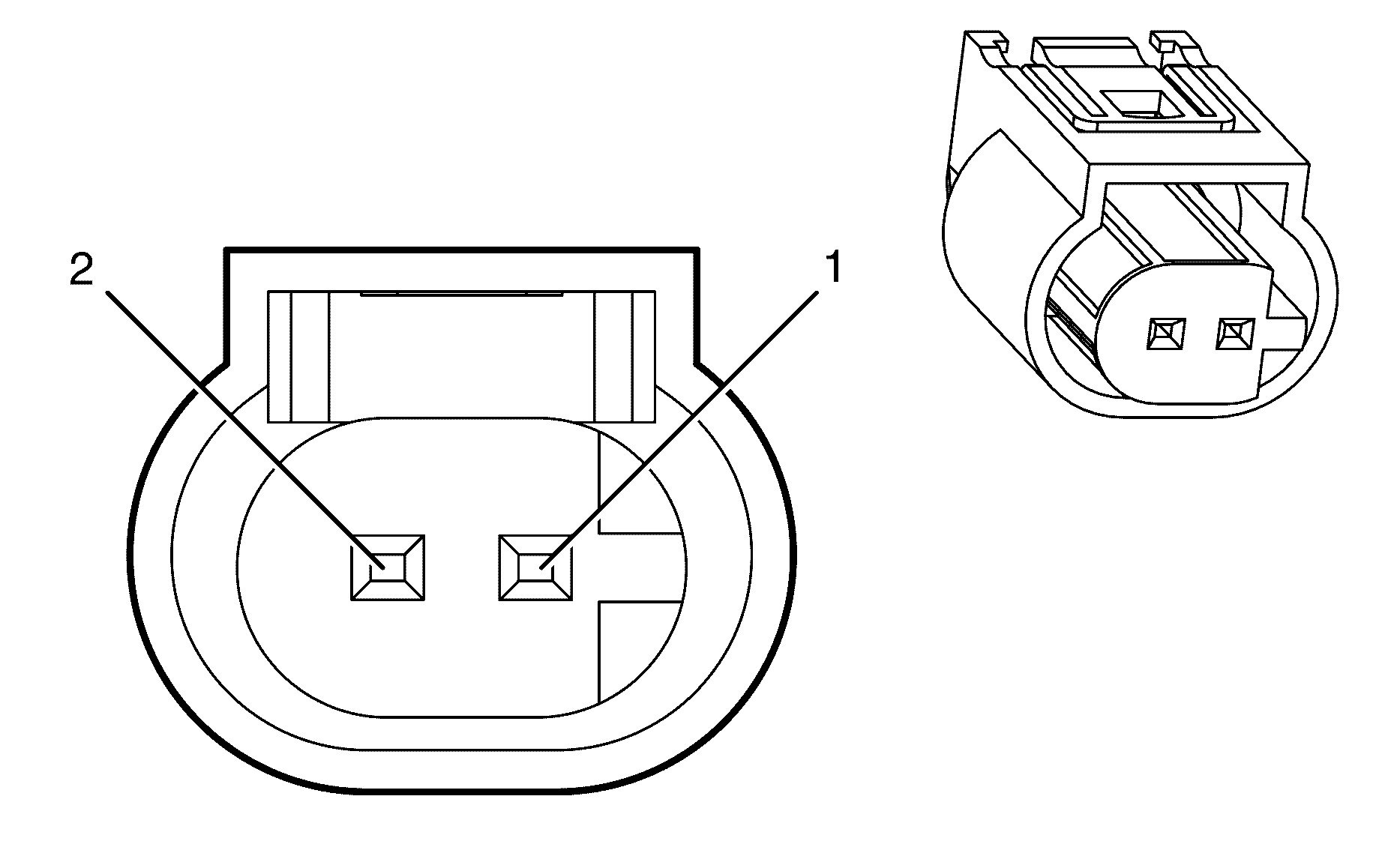
Connector Part Information
|
Terminal Part Information
|
Pin | Wire Color | Circuit No. | Function |
|---|---|---|---|
1 | 0.5 BK | 350 | Ground |
2 | 0.5 PU | 309 | Left Park Lamp Supply Voltage |
Side Marker Lamp - Left Rear

Connector Part Information
|
Terminal Part Information
|
Pin | Wire Color | Circuit No. | Function |
|---|---|---|---|
1 | 0.5 BN | 709 | Left Park Lamp Supply Voltage |
2 | 0.5 WH | 20 | Stop Lamp Supply Voltage |
Side Marker Lamp - Right Front

Connector Part Information
|
Terminal Part Information
|
Pin | Wire Color | Circuit No. | Function |
|---|---|---|---|
1 | 0.5 BK | 350 | Ground |
2 | 0.5 BN/WH | 709 | Right Park Lamp Supply Voltage |
Side Marker Lamp - Right Rear

Connector Part Information
|
Terminal Part Information
|
Pin | Wire Color | Circuit No. | Function |
|---|---|---|---|
1 | 0.5 BN | 309 | Right Park Lamp Supply Voltage |
2 | 0.5 WH | 20 | Stop Lamp Supply Voltage |
Speaker - Center I/P X1 (-UWP)
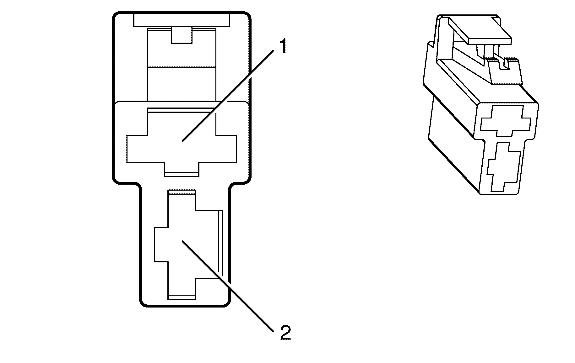
Connector Part Information
|
Terminal Part Information
|
Pin | Wire Color | Circuit No. | Function |
|---|---|---|---|
1 | 0.5 GY | 118 | Left Front Speaker Output (-) |
2 | 0.5 BN | 201 | Left Front Speaker Output (+) |
Speaker - Center I/P X2 (-UWP)

Connector Part Information
|
Terminal Part Information
|
Pin | Wire Color | Circuit No. | Function |
|---|---|---|---|
1 | 0.5 D-GN | 117 | Right Front Speaker Output (-) |
2 | 0.5 L-GN | 200 | Right Front Speaker Output (+) |
Speaker - Center I/P (UWP)
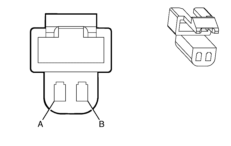
Connector Part Information
|
Terminal Part Information
|
Pin | Wire Color | Circuit No. | Function |
|---|---|---|---|
A | 0.5 L-BU | 1960 | Front Center Speaker Output (-) |
B | 0.5 OG | 1860 | Front Center Speaker Output (+) |
Speaker - Left Front

Connector Part Information
|
Terminal Part Information
|
Pin | Wire Color | Circuit No. | Function |
|---|---|---|---|
1 | 0.5 GY | 118 | Left Front Speaker Output (-) |
2 | 0.5 BN | 201 | Left Front Speaker Output (+) |
Speaker - Left Front Tweeter
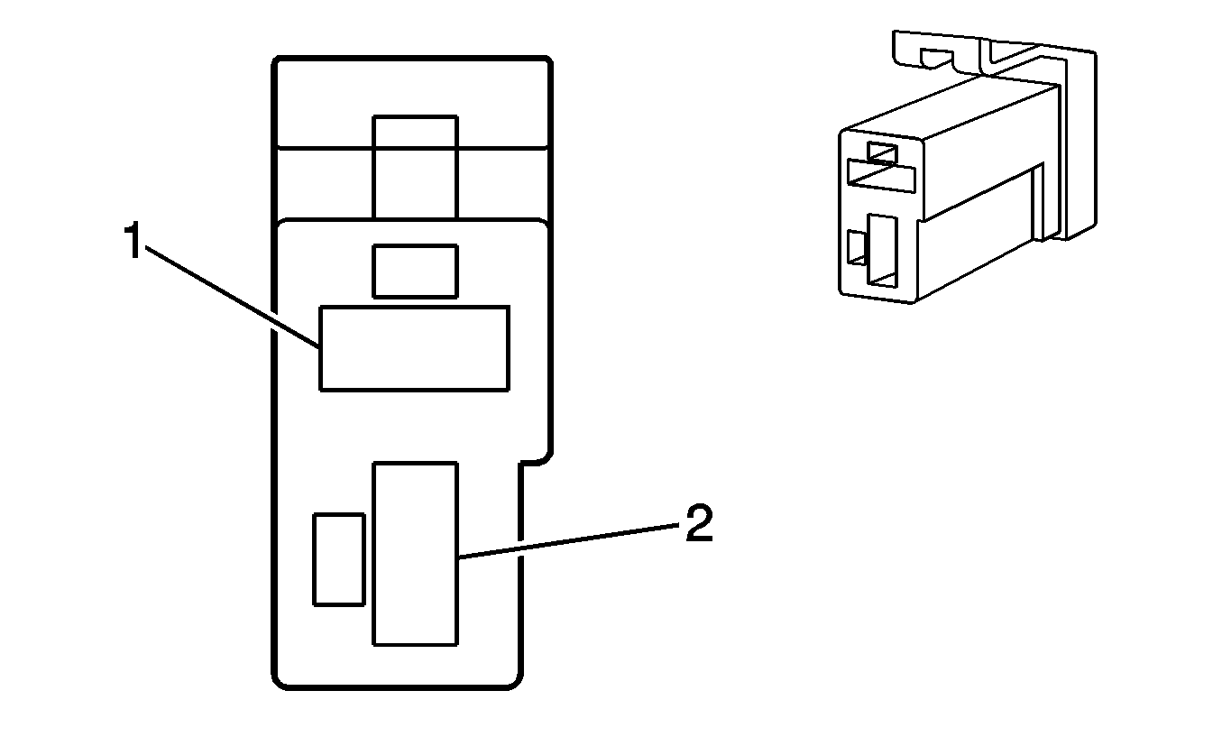
|
Terminal Part Information
|
Pin | Wire Color | Circuit No. | Function |
|---|---|---|---|
1 | 0.5 BN | 201 | Left Front Speaker Output (+) |
2 | 0.5 GY | 118 | Left Front Speaker Output (-) |
Speaker - Left Rear

Connector Part Information
|
Terminal Part Information
|
Pin | Wire Color | Circuit No. | Function |
|---|---|---|---|
1 | 0.5 YE/RD | 116 | Left Rear Speaker Output (-) |
2 | 0.5 BN | 199 | Left Rear Speaker Output (+) |
Speaker - Left Subwoofer (UWP)
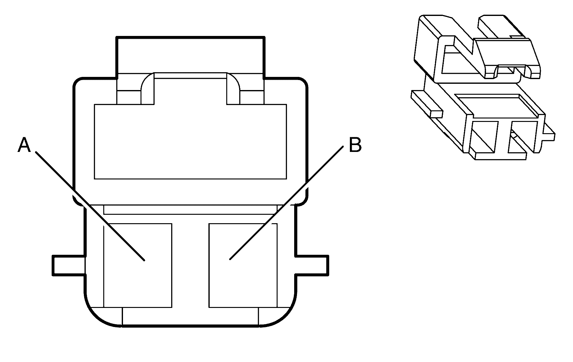
Connector Part Information
|
Terminal Part Information
|
Pin | Wire Color | Circuit No. | Function |
|---|---|---|---|
A | 1.25 D-BU/WH | 346 | Left Rear Subwoofer Speaker Output (+) |
B | 1.25 L-GN/BK | 1794 | Left Rear Subwoofer Speaker Output (-) |
Speaker - Right Front

Connector Part Information
|
Terminal Part Information
|
Pin | Wire Color | Circuit No. | Function |
|---|---|---|---|
1 | 0.5 D-GN | 200 | Right Front Speaker Output (+) |
2 | 0.5 L-GN | 117 | Right Front Speaker Output (-) |
Speaker - Right Front Tweeter

|
Terminal Part Information
|
Pin | Wire Color | Circuit No. | Function |
|---|---|---|---|
A | 0.5 L-GN | 200 | Right Front Speaker Output (+) |
B | 0.5 D-GN | 117 | Right Front Speaker Output (-) |
Speaker - Right Rear

|
Terminal Part Information
|
Pin | Wire Color | Circuit No. | Function |
|---|---|---|---|
A | 0.5 L-BU | 115 | Right Rear Speaker Output (-) |
B | 0.5 D-BU | 46 | Right Rear Speaker Output (+) |
Speaker - Right Subwoofer (UWP)

|
Terminal Part Information
|
Pin | Wire Color | Circuit No. | Function |
|---|---|---|---|
A | 1.25 D-GN | 1795 | Right Rear Subwoofer Speaker Output (+) |
B | 1.25 L-BU/BK | 315 | Right Rear Subwoofer Speaker Output (-) |
Starter Motor X1
Terminal Part Information
|
Pin | Wire Color | Circuit No. | Function |
|---|---|---|---|
A | 3 PU | 6 | Starter Solenoid Crank Voltage |
Starter Motor X2
Terminal Part Information
|
Pin | Wire Color | Circuit No. | Function |
|---|---|---|---|
A | 3 RD | 1 | Battery Voltage |
Steering Angle Sensor
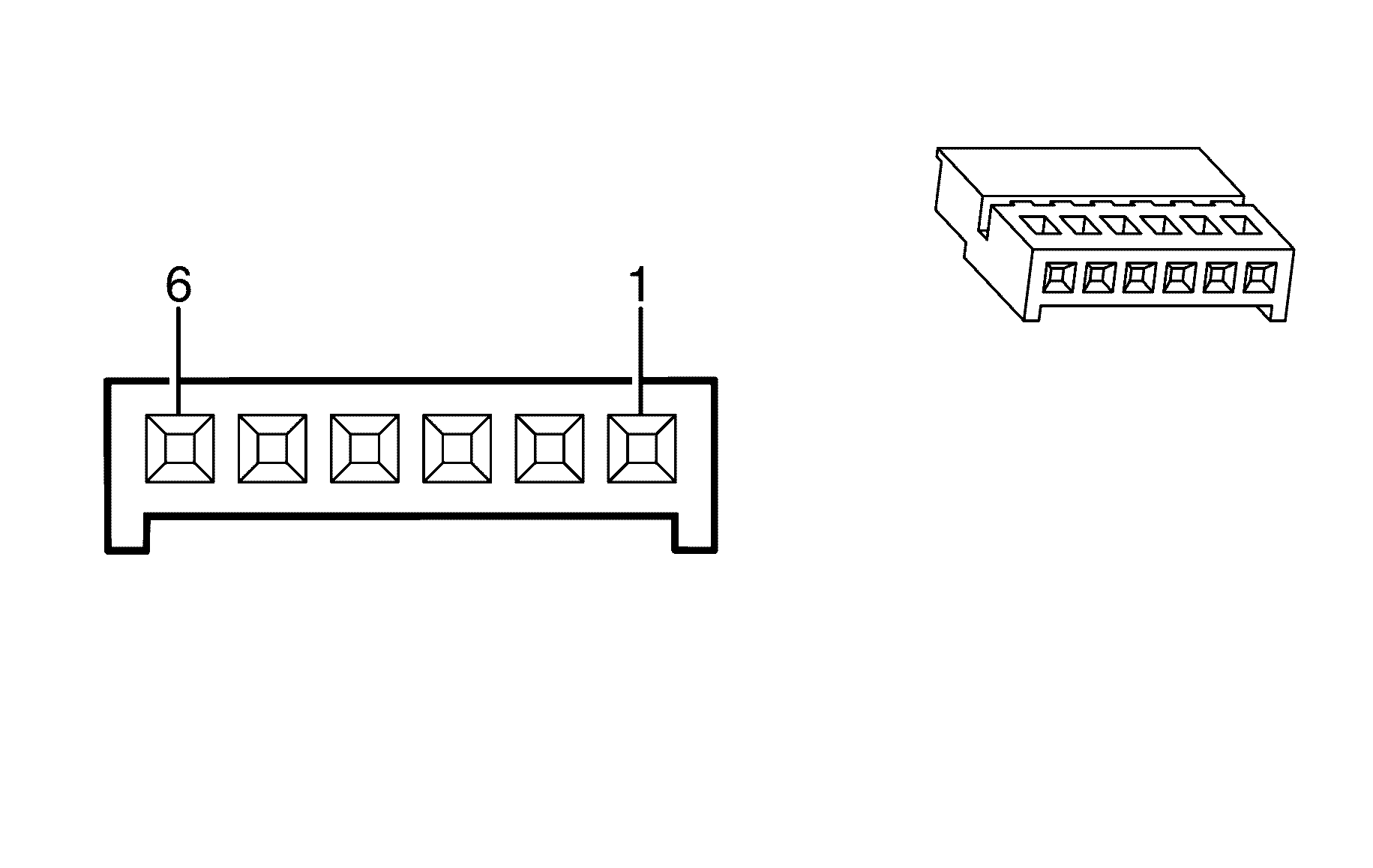
|
Terminal Part Information
|
Pin | Wire Color | Circuit No. | Function |
|---|---|---|---|
1 | 0.5 PU | 2501 | High Speed GMLAN Serial Data Bus (-) |
2 | 0.5 D-BU | 2501 | High Speed GMLAN Serial Data Bus (-) |
3 | 0.5 GY | 2500 | High Speed GMLAN Serial Data Bus (+) |
4 | 0.5 BN | 2500 | High Speed GMLAN Serial Data Bus (+) |
5 | 0.5 L-GN | 5986 | Communication Enable Relay Supply Voltage |
6 | 0.5 OG | 2088 | Steering Wheel Position Sensor Low Reference |
Steering Wheel Controls Switch Assembly
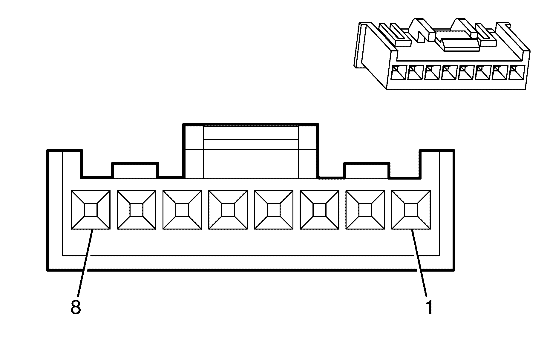
|
Terminal Part Information
|
Pin | Wire Color | Circuit No. | Function |
|---|---|---|---|
1 | 0.3 GY/BU | 7367 | Right Steering Wheel Scroll 2 |
2 | 0.3 YE | 7364 | Right Steering Wheel Scroll 1 |
3 | 0.3 BN | 7312 | Left Steering Wheel Scroll 1 |
4 | 0.3 L-BU | 7313 | Left Steering Wheel Scroll 2 |
5 | 0.3 D-GN | 897 | Steering Wheel Controls Low Reference |
6 | 0.3 OG/BK | 5201 | Steering Wheel Controls Signal |
7 | 0.3 BK/WH | 1551 | Ground |
8 | 0.3 PU | 7005 | I/P Dimming Control |
Sunload Sensor (CJ2)
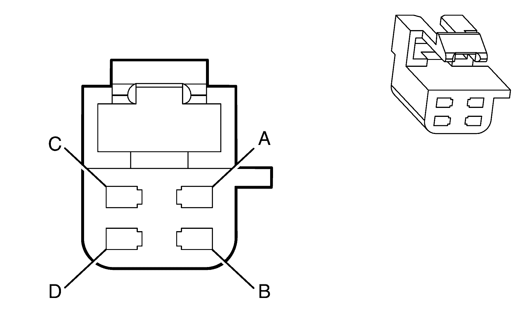
Connector Part Information
|
Terminal Part Information
|
Pin | Wire Color | Circuit No. | Function |
|---|---|---|---|
A | 0.3 L-BU/BK | 7425 | Left Solar Sensor |
B | 0.3 GY | 7424 | Right Solar Sensor |
C | 0.3 BN | 61 | Low Reference |
D | 0.3 L-GN/BK | 1137 | DRL Ambient Light Sensor Signal |
Sunroof Control Module (CF5)
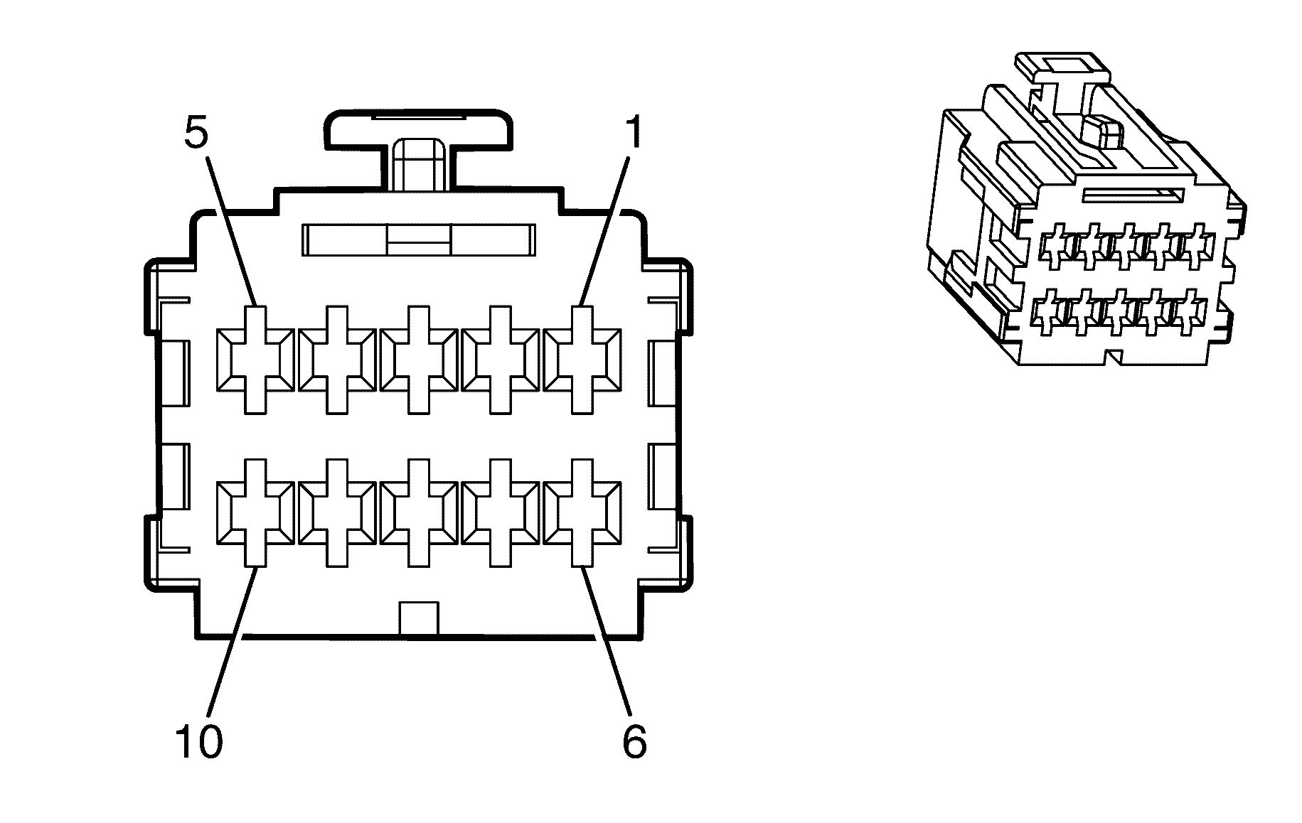
|
Terminal Part Information
|
Pin | Wire Color | Circuit No. | Function |
|---|---|---|---|
1 | 1.25 BK | 850 | Ground |
2 | 0.3 D-GN | 5027 | Sunroof Switch - Data 1 |
3 | 0.3 YE | 5028 | Sunroof Switch - Data 2 |
4 | 0.3 OG | 5029 | Sunroof Switch - Data 3 |
5 | 0.3 WH | 5030 | Sunroof Switch - Data 4 |
6 | 1.25 OG/BU | 3040 | Battery Voltage Supply |
7-8 | -- | -- | Not Used |
9 | 0.5 YE | 443 | Ignition Voltage 1 |
10 | -- | -- | Not Used |
Sunroof Switch (CF5)
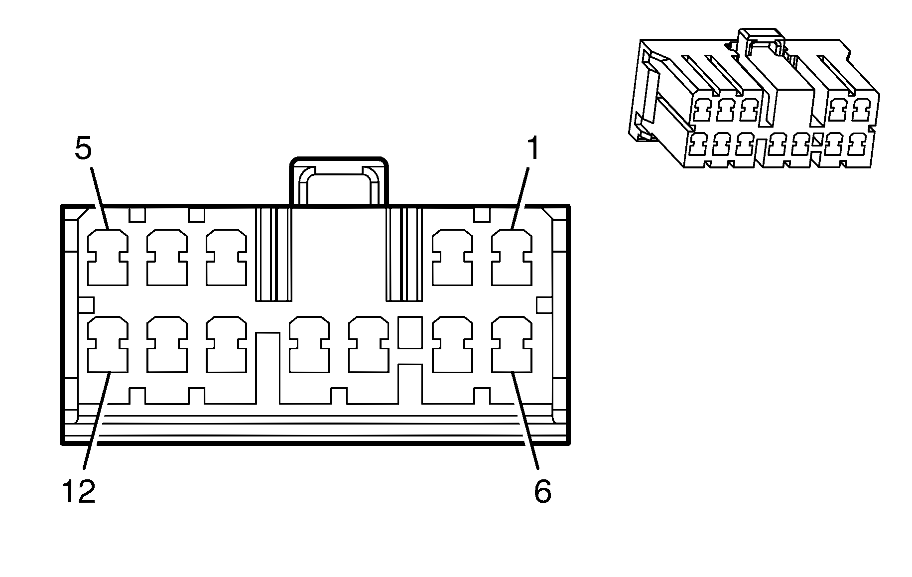
|
Terminal Part Information
|
Pin | Wire Color | Circuit No. | Function |
|---|---|---|---|
1 | 0.5 BK | 850 | Ground |
2 | 0.3 D-GN | 5027 | Sunroof Switch - Data 1 |
3 | 0.3 YE | 5028 | Sunroof Switch - Data 2 |
4 | -- | -- | Not Used |
5 | 0.3 OG | 5029 | Sunroof Switch - Data 3 |
6 | 0.3 WH | 5030 | Sunroof Switch - Data 4 |
Sunshade - Left
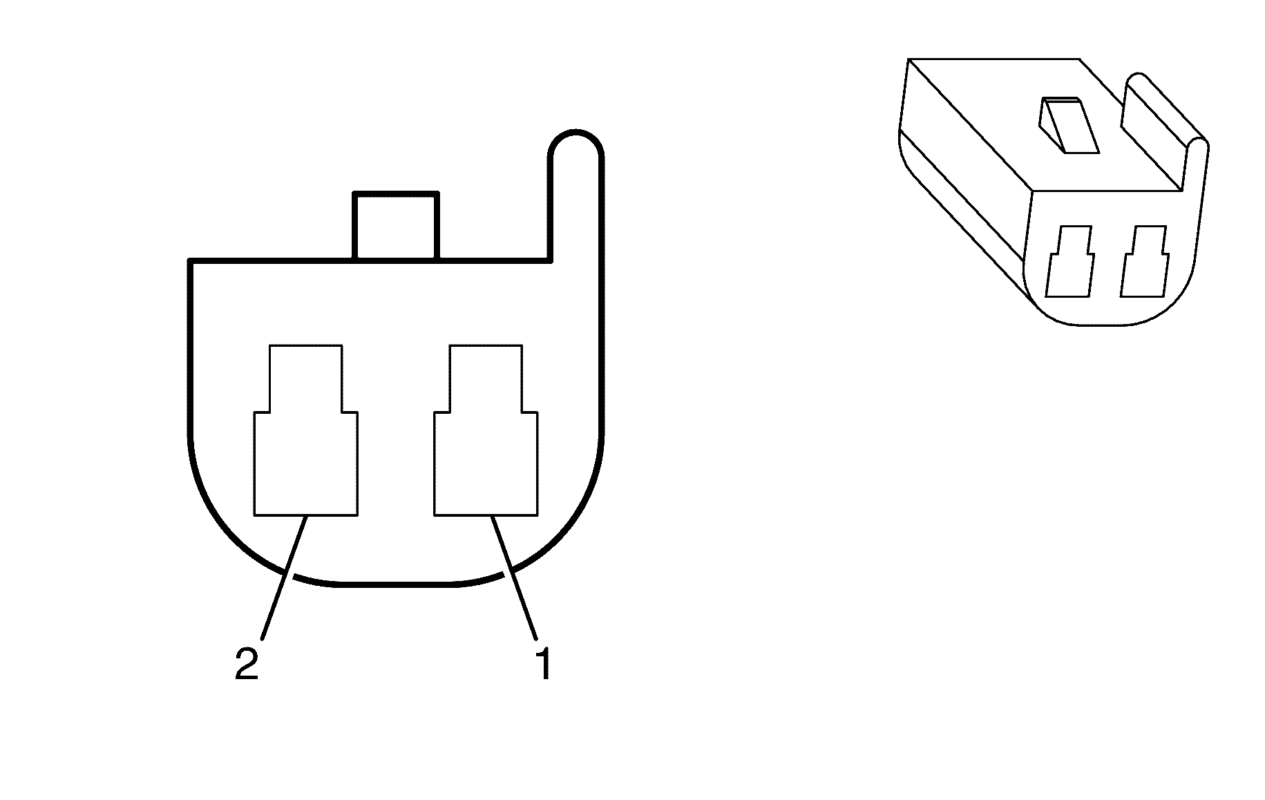
|
Terminal Part Information
|
Pin | Wire Color | Circuit No. | Function |
|---|---|---|---|
1 | 0.5 BK/WH | 851 | Ground |
2 | 0.5 OG | 1732 | Courtesy Lamps Supply Voltage |
Sunshade - Right

|
Terminal Part Information
|
Pin | Wire Color | Circuit No. | Function |
|---|---|---|---|
1 | 0.5 BK/WH | 851 | Ground |
2 | 0.5 OG | 1732 | Courtesy Lamps Supply Voltage |
Tail/Stop Lamp - Left
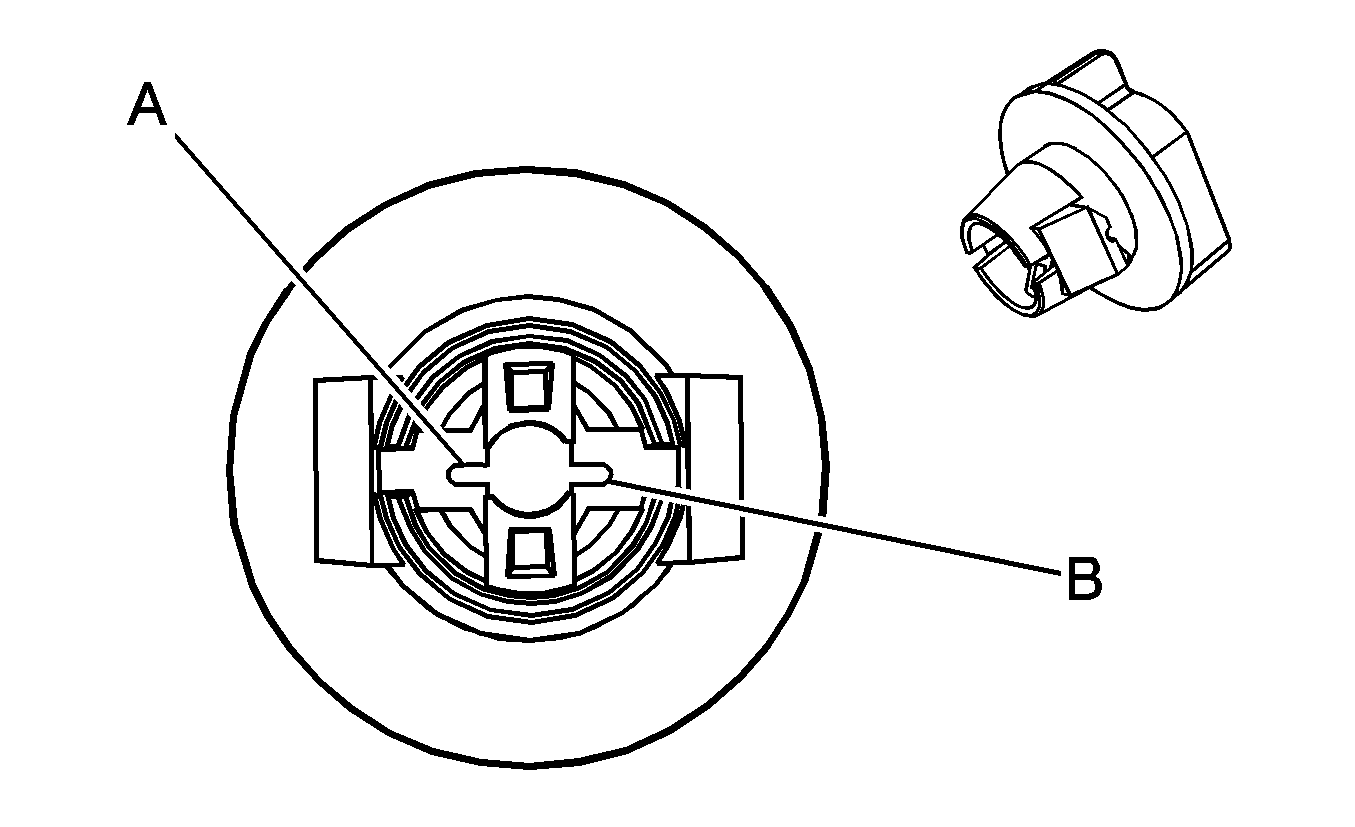
|
Terminal Part Information
|
Pin | Wire Color | Circuit No. | Function |
|---|---|---|---|
1 | 0.5 RD | 1851 | Ground |
2 | -- | -- | Not Used |
3 | 0.5 BN | 709 | Left Park Lamp Supply Voltage |
4 | 0.5 WH | 20 | Stop Lamp Supply Voltage |
Tail/Stop Lamp - Right

|
Terminal Part Information
|
Pin | Wire Color | Circuit No. | Function |
|---|---|---|---|
1 | 0.5 RD | 1851 | Ground |
2 | -- | -- | Not Used |
3 | 0.5 BN | 309 | Right Park Lamp Supply Voltage |
4 | 0.5 WH | 20 | Stop Lamp Supply Voltage |
Theft Deterrent Alarm Siren X1

|
Terminal Part Information
|
Pin | Wire Color | Circuit No. | Function |
|---|---|---|---|
A | 0.75 D-GN | 1149 | Content Theft Horn Control |
Theft Deterrent Alarm Siren X2

|
Terminal Part Information
|
Pin | Wire Color | Circuit No. | Function |
|---|---|---|---|
A | 0.75 BK | 350 | Ground |
Theft Deterrent Module (TDM)
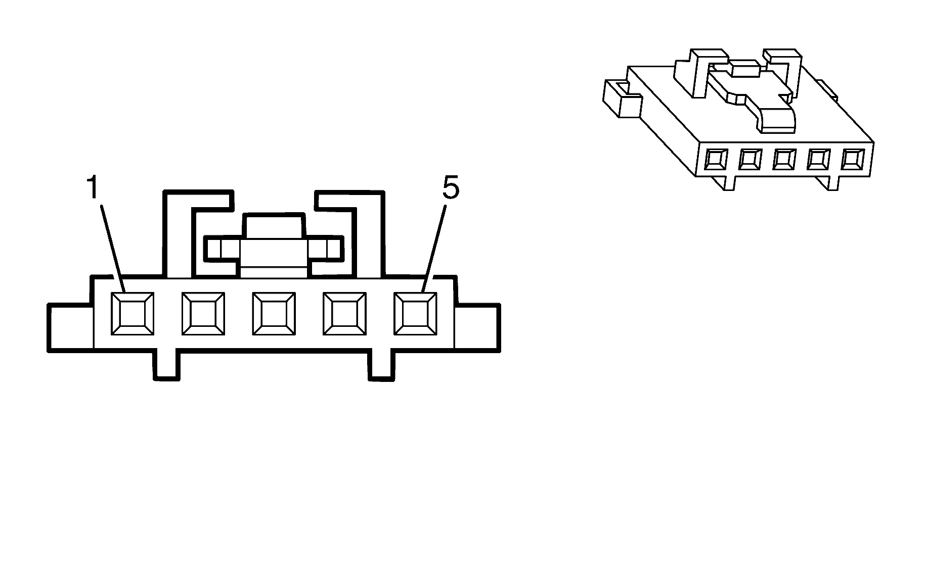
|
Terminal Part Information
|
Pin | Wire Color | Circuit No. | Function |
|---|---|---|---|
1 | 0.3 OG/BK | 1040 | Battery Positive Voltage |
2 | 0.3 BN | 4 | Ignition 1 Voltage |
3 | 0.3 BK | 850 | Ground |
4 | -- | -- | Not Used |
5 | 0.35 D-GN | 9206 | Low Speed GMLAN Serial Data |
Throttle Body
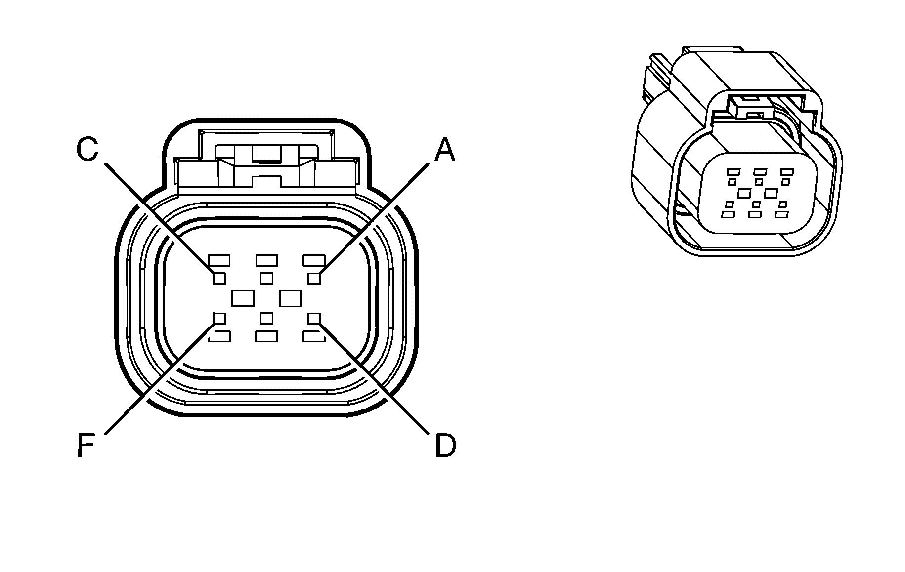
|
Terminal Part Information
|
Pin | Wire Color | Circuit No. | Function |
|---|---|---|---|
A | 0.75 BN | 582 | TAC Motor Control - 2 |
B | 0.75 YE | 581 | TAC Motor Control - 1 |
C | 0.5 BN/BK | 2752 | Low Reference |
D | 0.5 D-GN | 485 | TP Sensor 1 Signal |
E | 0.5 GY | 2701 | 5-Volt Reference |
F | 0.5 PU | 486 | TP Sensor 2 Signal |
Torque Converter Clutch (TCC) Pulse Width Modulation (PWM) Solenoid Valve
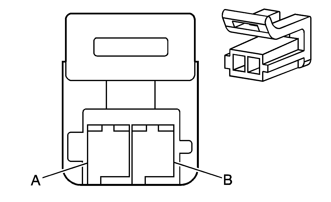
Connector Part Information
|
Terminal Part Information
|
Pin | Wire Color | Circuit No. | Function |
|---|---|---|---|
A | 0.5 YE | 418 | TCC PWM Solenoid Valve Control |
B | 0.5 WH | 1525 | Clutch Pressure Control Solenoid Valve 1 High Control |
Transmission Control Module (TCM) (M82)
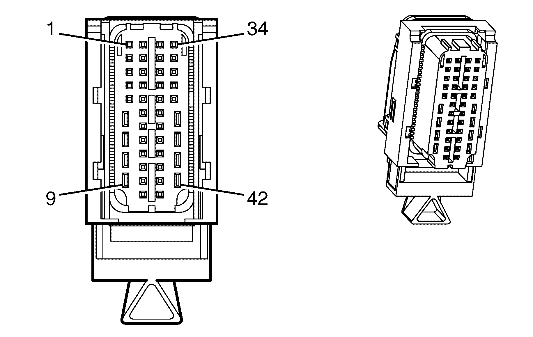
|
Terminal Part Information
|
Pin | Wire Color | Circuit No. | Function |
|---|---|---|---|
1 | 0.5 L-GN/BK | 822 | VSS Low Signal |
2 | 0.5 PU/WH | 821 | VSS High Signal |
3 | 0.5 OG/BK | 1228 | PC Solenoid Valve High Control |
4 | 0.5 BN | 418 | TCC PWM Solenoid Valve Control |
5 | 0.5 D-BU | 5985 | Accessory Wakeup Serial Data |
6 | 0.75 BK | 450 | Ground |
7 | -- | -- | Not Used |
8 | 0.75 OG | 1525 | Clutch Pressure Control Solenoid Valve 1 High Control |
9 | 0.75 PK | 439 | Ignition 1 Voltage |
10 | 0.5 OG | 1983 | Transmission Turbine Speed Switch Signal |
11 | 0.5 L-BU | 1984 | Transmission Turbine Speed Switch Low Reference |
12-14 | -- | -- | Not Used |
15 | 0.5 YE/BK | 1227 | TFT Sensor Signal |
16-17 | -- | -- | Not Used |
18 | 0.5 YE/BK | 1223 | Shift Solenoid B Valve Control |
19 | 0.5 WH | 898 | Shift Solenoid Valve 3 High Control |
20 | 0.5 BN/BK | 9002 | High Speed GMLAN Serial Data Bus+ |
21 | 0.5 BN | 9003 | High Speed GMLAN Serial Data Bus- |
22-23 | -- | -- | Not Used |
24 | 0.5 YE | 772 | Transmission Range Switch Signal B |
25 | 0.5 GY | 773 | Transmission Range Switch Signal C |
26 | 0.5 BN/WH | 2762 | Low Reference |
27 | 0.75 OG/YE | 3640 | Battery Positive Voltage |
28 | -- | -- | Not Used |
29 | 0.5 L-BU/WH | 1229 | PC Solenoid Valve Low Control |
30 | 0.5 L-GN | 1222 | Shift Solenoid A Valve Control |
31 | -- | -- | Not Used |
32 | 0.5 BN/BK | 9004 | High Speed GMLAN Serial Data Bus+ |
33 | 0.5 BN | 9005 | High Speed GMLAN Serial Data Bus- |
34-35 | -- | -- | Not Used |
36 | 0.5 BN/YE | 771 | Transmission Range Switch Signal A |
37 | 0.5 WH | 776 | Transmission Range Switch Signal P |
38 | 0.5 WH/BU | 17 | Stop Lamp Switch Signal |
39-42 | -- | -- | Not Used |
Turn Signal Lamp - Left Rear

Connector Part Information
|
Terminal Part Information
|
Pin | Wire Color | Circuit No. | Function |
|---|---|---|---|
1 | 0.85 D-BU | 1334 | Left Turn Signal Lamps Supply Voltage |
2 | 0.85 BK | 1850 | Ground |
Turn Signal Lamp - Right Rear

Connector Part Information
|
Terminal Part Information
|
Pin | Wire Color | Circuit No. | Function |
|---|---|---|---|
1 | 0.85 D-BU | 1335 | Right Turn Signal Lamps Supply Voltage |
2 | 0.85 BK | 1850 | Ground |
Turn Signal Repeater Lamp - Left

Connector Part Information
|
Terminal Part Information
|
Pin | Wire Color | Circuit No. | Function |
|---|---|---|---|
1 | 0.5 BK | 2050 | Ground |
2 | 0.5 YE/BK | 1334 | Left Rear Turn Signal Lamp Supply Voltage |
Turn Signal Repeater Lamp - Right

Connector Part Information
|
Terminal Part Information
|
Pin | Wire Color | Circuit No. | Function |
|---|---|---|---|
1 | 0.5 BK | 1350 | Ground |
2 | 0.5 D-GN/WH | 1335 | Right Rear Turn Signal Lamp Supply Voltage |
Turn Signal/Multifunction Switch
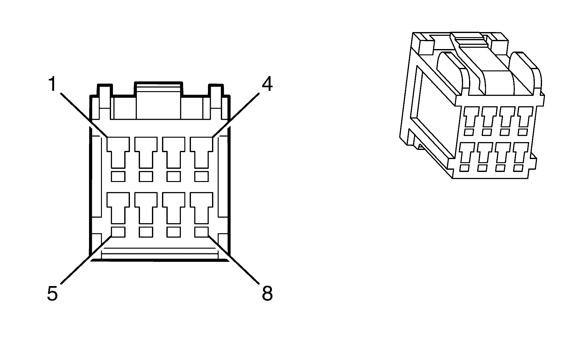
Connector Part Information
|
Terminal Part Information
|
Pin | Wire Color | Circuit No. | Function |
|---|---|---|---|
1 | 0.3 BK | 850 | Ground |
2 | 0.3 BN/RD | 1356 | Flash To Pass Switch Signal |
3 | 0.3 PU/YE | 524 | Headlamp Dimmer Switch High Beam Signal |
4 | 0.3 BK | 850 | Ground |
5 | 0.5 GY | 1884 | Cruise Control Switch Signal |
6 | 0.3 PU | 1375 | Steering Wheel Control Supply Voltage |
7 | 0.3 D-BU/WH | 1415 | Right Front Turn Signal Switch Signal |
8 | 0.3 L-BU/WH | 1414 | Left Front Turn Signal Switch Signal |
Valve Lifter Oil Manifold (VLOM) Assembly

Connector Part Information
|
Terminal Part Information
|
Pin | Wire Color | Circuit No. | Function |
|---|---|---|---|
A | 0.75 OG | 5494 | Cylinder Shut Off Solenoid 4 |
B | 0.75 GY | 5493 | Cylinder Shut Off Solenoid 3 |
C | 0.75 D-BU | 5491 | Cylinder Shut Off Solenoid 1 |
D | 0.75 D-GN/BK | 5492 | Cylinder Shut Off Solenoid 2 |
E | 0.75 PK/BU | 5293 | Ignition 1 Voltage |
Vehicle Communication Interface Module (VCIM) X1

Connector Part Information
|
Terminal Part Information
|
Pin | Wire Color | Circuit No. | Function |
|---|---|---|---|
1 | 0.35 D-GN | 5060 | Low Speed GMLAN Serial Data |
2 | 0.3 BN/WH | 2517 | Keypad Red LED Signal |
3 | 0.3 YE/BK | 2516 | Keypad Green LED Signal |
4-5 | -- | -- | Not Used |
6 | 0.3 L-GN/BK | 2515 | Keypad Supply Voltage |
7 | 0.5 BK | 1050 | Ground |
8-9 | -- | -- | Not Used |
10 | 0.5 BN/BK | 9008 | High Speed GMLAN Serial Data Bus+ |
11 | 0.3 GN/WH | 2514 | Keypad Signal |
12 | 0.5 BN | 9009 | High Speed GMLAN Serial Data Bus- |
13 | 0.5 YE/BK | 950 | VCIM Battery Low Reference |
14 | 0.5 BN/WH | 9940 | VCIM Battery Power |
15 | 0.5 OG | 3340 | Battery Positive Voltage |
16 | -- | -- | Not Used |
Vehicle Communication Interface Module (VCIM) X2
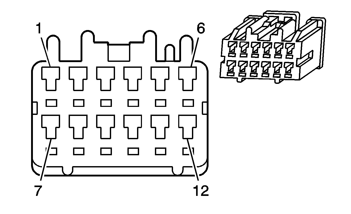
Connector Part Information
|
Terminal Part Information
|
Pin | Wire Color | Circuit No. | Function |
|---|---|---|---|
1 | 0.3 D-BU | 658 | Cellular Telephone Voice Signal |
2 | 0.3 L-BU | 659 | Cellular Telephone Voice Low Reference |
3 | 0.5 BN/BK | 9010 | High Speed GMLAN Serial Data Bus+ |
4 | 0.5 BN | 9011 | High Speed GMLAN Serial Data Bus- |
5-7 | -- | -- | Not Used |
8 | 0.5 BK | -- | Ground |
9 | 0.3 D-GN | 0655 | Cellular Microphone Signal |
10 | 0.3 BK | 1782 | Drain Wire |
11 | -- | -- | Not Used |
12 | 0.3 WH | 700 | Telephone Audio Signal Mute |
Vehicle Communication Interface Module (VCIM) Battery

Connector Part Information
|
Terminal Part Information
|
Pin | Wire Color | Circuit No. | Function |
|---|---|---|---|
A | 0.5 BN/WH | 9940 | VCIM Battery Power |
B | 0.5 YE/BK | 950 | VCIM Battery Low Reference |
Wheel Speed Sensor (WSS) - Left Front
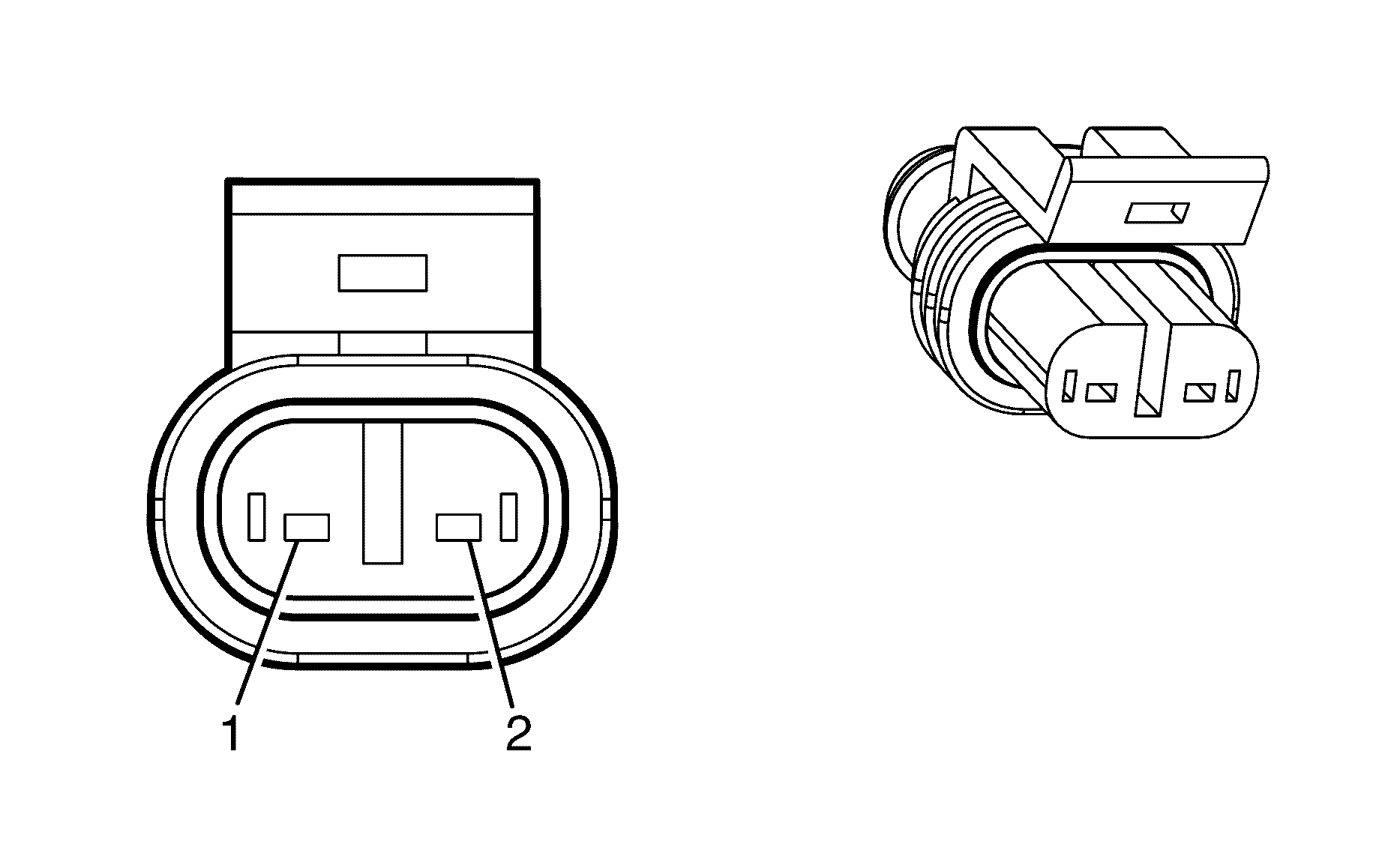
Connector Part Information
|
Terminal Part Information
|
Pin | Wire Color | Circuit No. | Function |
|---|---|---|---|
1 | 0.75 BN | 830 | Wheel Speed Sensor Signal Left Front |
2 | 0.75 BK | 7064 | Wheel Speed Sensor Supply Voltage Left Front |
Wheel Speed Sensor (WSS) - Left Rear

Connector Part Information
|
Terminal Part Information
|
Pin | Wire Color | Circuit No. | Function |
|---|---|---|---|
1 | 0.5 BN/BK | 884 | Wheel Speed Sensor Signal Left Rear |
2 | 0.5 GY | 7127 | Wheel Speed Sensor Supply Voltage Left Rear |
Wheel Speed Sensor (WSS) - Right Front

Connector Part Information
|
Terminal Part Information
|
Pin | Wire Color | Circuit No. | Function |
|---|---|---|---|
1 | 0.75 BN | 872 | Wheel Speed Sensor Signal Right Front |
2 | 0.75 BK | 7065 | Wheel Speed Sensor Supply Voltage Right Front |
Wheel Speed Sensor (WSS) - Right Rear

Connector Part Information
|
Terminal Part Information
|
Pin | Wire Color | Circuit No. | Function |
|---|---|---|---|
1 | 0.5 BN | 882 | Wheel Speed Sensor Signal Right Rear |
2 | 0.5 GY | 7128 | Wheel Speed Sensor Supply Voltage Right Rear |
Window Control Module
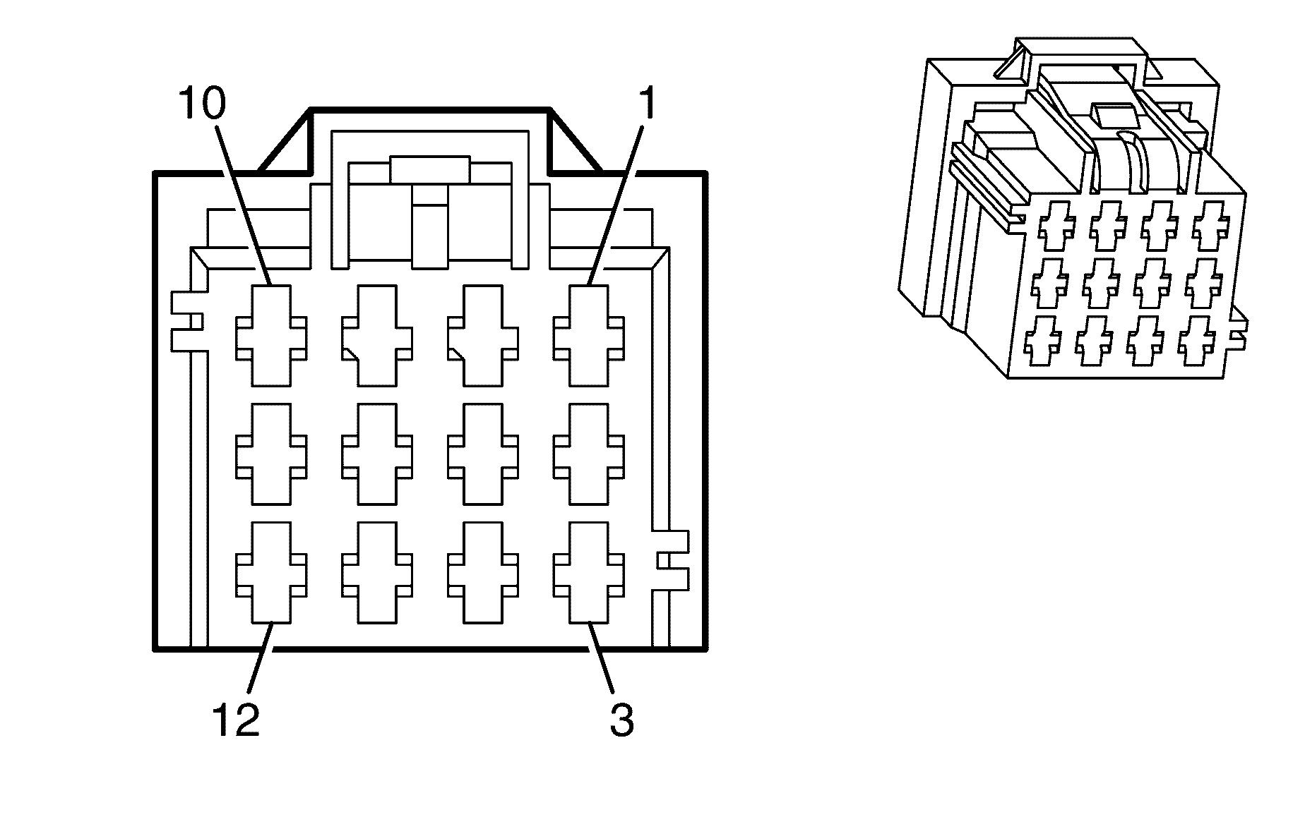
Connector Part Information
|
Terminal Part Information
|
Pin | Wire Color | Circuit No. | Function |
|---|---|---|---|
1 | 2 BU/WH | 666 | Power Window Motor Right Front Up Control |
2 | 2 BN/OG | 165 | Power Window Motor Left Front Down Control |
3 | 0.5 L-BU | 166 | Power Window Master Switch Right Front Up Signal |
4 | -- | -- | Not Used |
5 | 2 BK | 1350 | Ground |
6 | 0.5 BN | 1300 | Power Window Master Switch Left Front Up Signal |
7 | -- | -- | Not Used |
8 | 2 D-GN | 1001 | RAP Supply Voltage |
9 | 0.5 D-GN/BK | 167 | Power Window Master Switch Right Front Down Signal |
10 | 2 BN | 667 | Power Window Motor Right Front Down Control |
11 | 2 D-BU | 164 | Power Window Motor Left Front Up Control |
12 | 0.5 GY/BU | 1136 | Power Window Master Switch Left Front Down Control Signal |
Window Motor - Driver
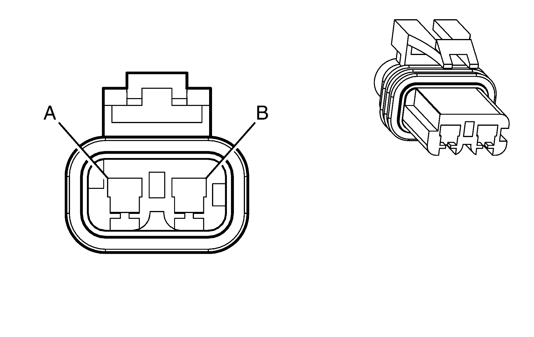
Connector Part Information
|
Terminal Part Information
|
Pin | Wire Color | Circuit No. | Function |
|---|---|---|---|
A | 2 D-BU/OG | 165 | Power Window Motor Left Front Down Control |
B | 2 D-BU | 164 | Power Window Motor Left Front Up Control |
Window Motor - Left Rear
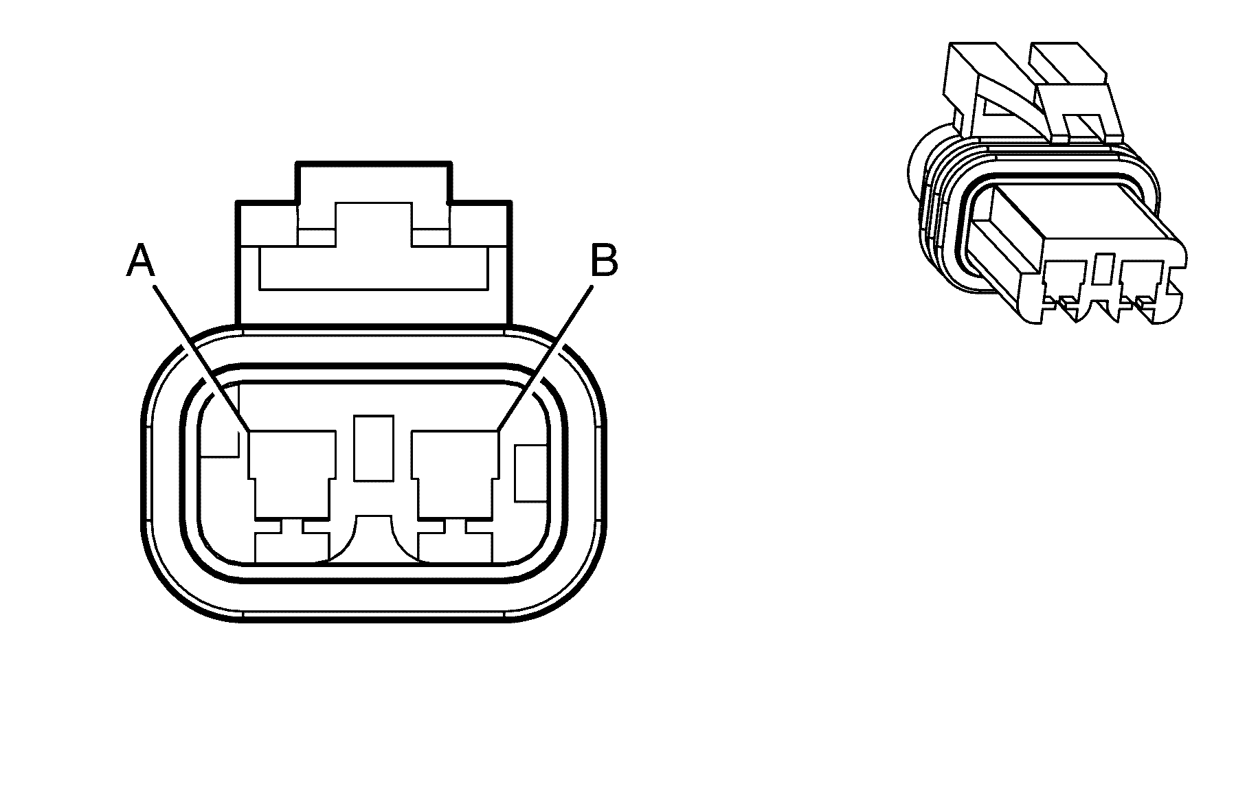
Connector Part Information
|
Terminal Part Information
|
Pin | Wire Color | Circuit No. | Function |
|---|---|---|---|
A | 2 BN | 669 | Power Window Motor Left Rear Down Control |
B | 2 D-BU | 668 | Power Window Motor Left Rear Up Control |
Window Motor - Passenger

Connector Part Information
|
Terminal Part Information
|
Pin | Wire Color | Circuit No. | Function |
|---|---|---|---|
A | 2 BN | 667 | Power Window Motor Right Front Down Control |
B | 2 D-BU/WH | 666 | Power Window Motor Right Front Up Control |
Window Motor - Right Rear

Connector Part Information
|
Terminal Part Information
|
Pin | Wire Color | Circuit No. | Function |
|---|---|---|---|
A | 2 BN | 671 | Power Window Motor Right Rear Down Control |
B | 2 D-BU | 670 | Power Window Motor Right Rear Up Control |
Window Switch - Left Rear
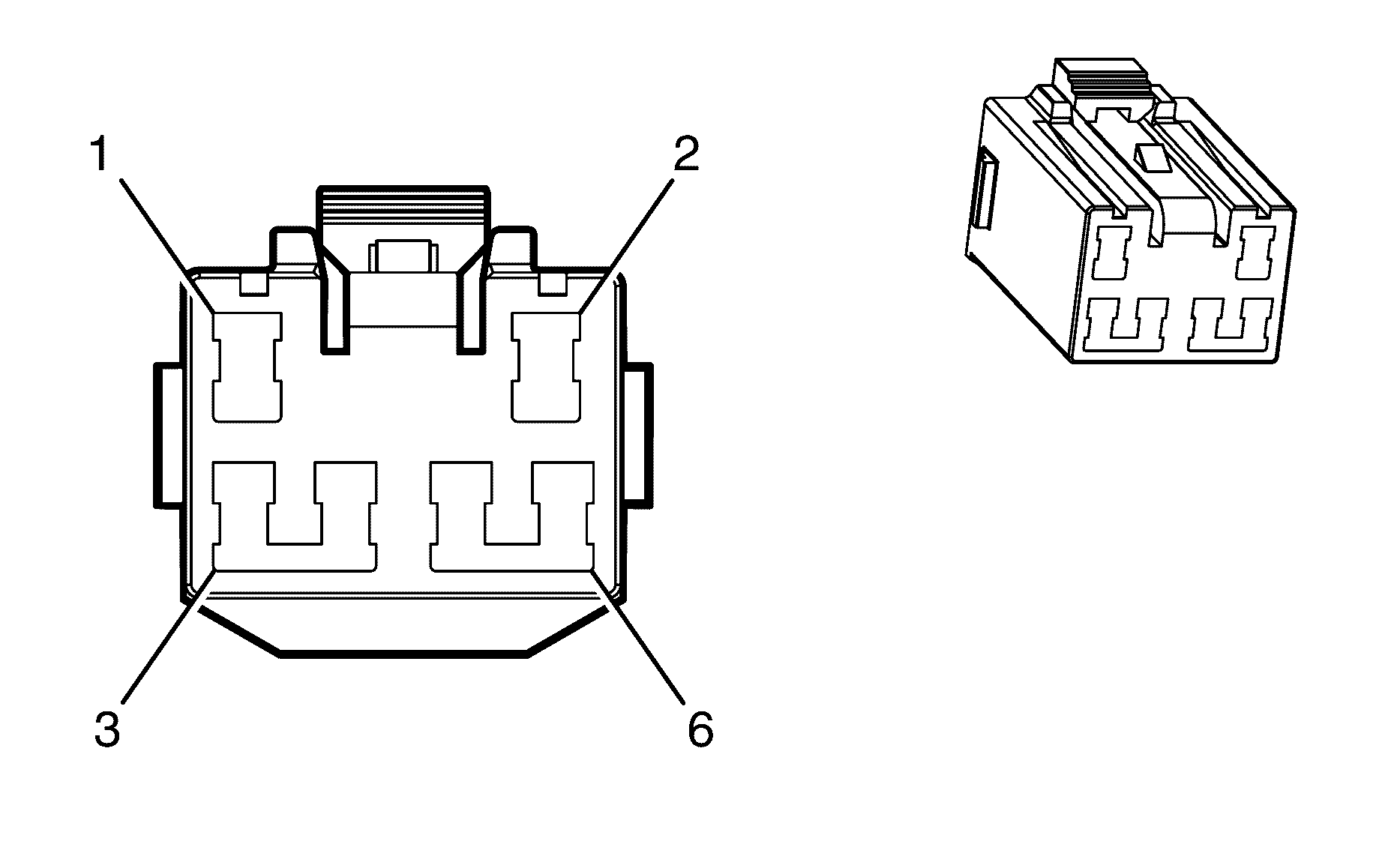
Connector Part Information
|
Terminal Part Information
|
Pin | Wire Color | Circuit No. | Function |
|---|---|---|---|
1 | 2 D-BU | 668 | Power Window Motor Left Rear Up Control |
2 | -- | -- | Not Used |
3 | 2 D-GN | 168 | Power Window Master Switch Left Rear Up Signal |
4 | 2 D-BU | 1307 | Power Window Master Switch Lockout Signal |
5 | 2 BN | 669 | Power Window Motor Left Rear Down Control |
6 | 2 PU | 169 | Power Window Master Switch Left Rear Down Signal |
Window Switch - Right Rear

Connector Part Information
|
Terminal Part Information
|
Pin | Wire Color | Circuit No. | Function |
|---|---|---|---|
1 | 2 D-BU | 670 | Power Window Motor Right Rear Up Control |
2 | -- | -- | Not Used |
3 | 2 L-GN | 170 | Power Window Master Switch Right Rear Up Signal |
4 | 2 D-BU | 1307 | Power Window Master Switch Lockout Signal |
5 | 2 BN | 671 | Power Window Motor Right Rear Down Control |
6 | 2 PU/WH | 171 | Power Window Master Switch Right Rear Down Signal |
Windshield Washer Fluid Pump
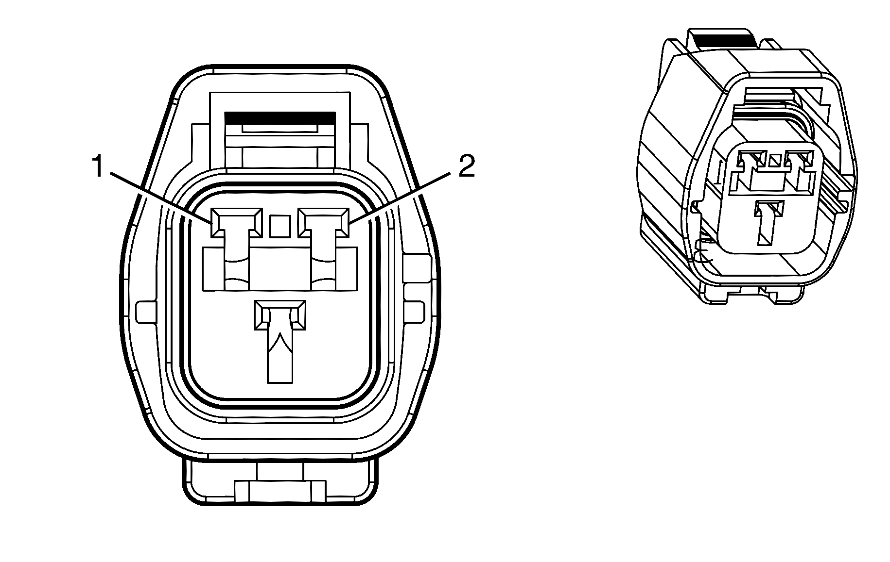
Connector Part Information
|
Terminal Part Information
|
Pin | Wire Color | Circuit No. | Function |
|---|---|---|---|
1 | 0.75 OG | 228 | Windshield Washer Pump Control |
2 | 0.75 BK | 250 | Ground |
Windshield Wiper Motor
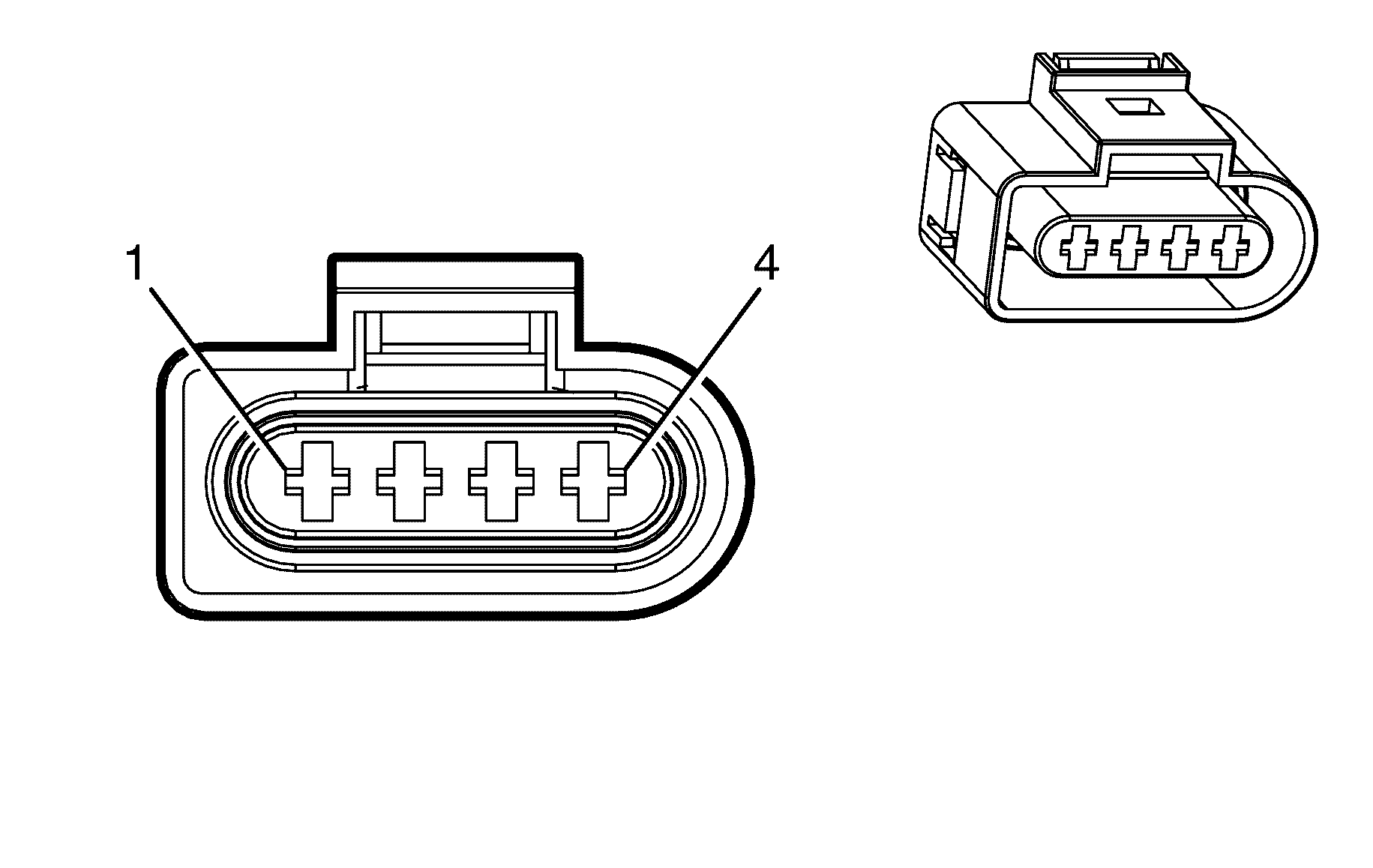
Connector Part Information
|
Terminal Part Information
|
Pin | Wire Color | Circuit No. | Function |
|---|---|---|---|
1 | 2 D-GN | 95 | Windshield Wiper Motor Low Speed |
2 | 2 BN/WH | 92 | Windshield Wiper Motor High Speed |
3 | 1.25 BK | 350 | Ground |
4 | 0.3 YE | 196 | Windshield Wiper Motor Park Switch Signal |
Windshield Wiper/Washer Switch
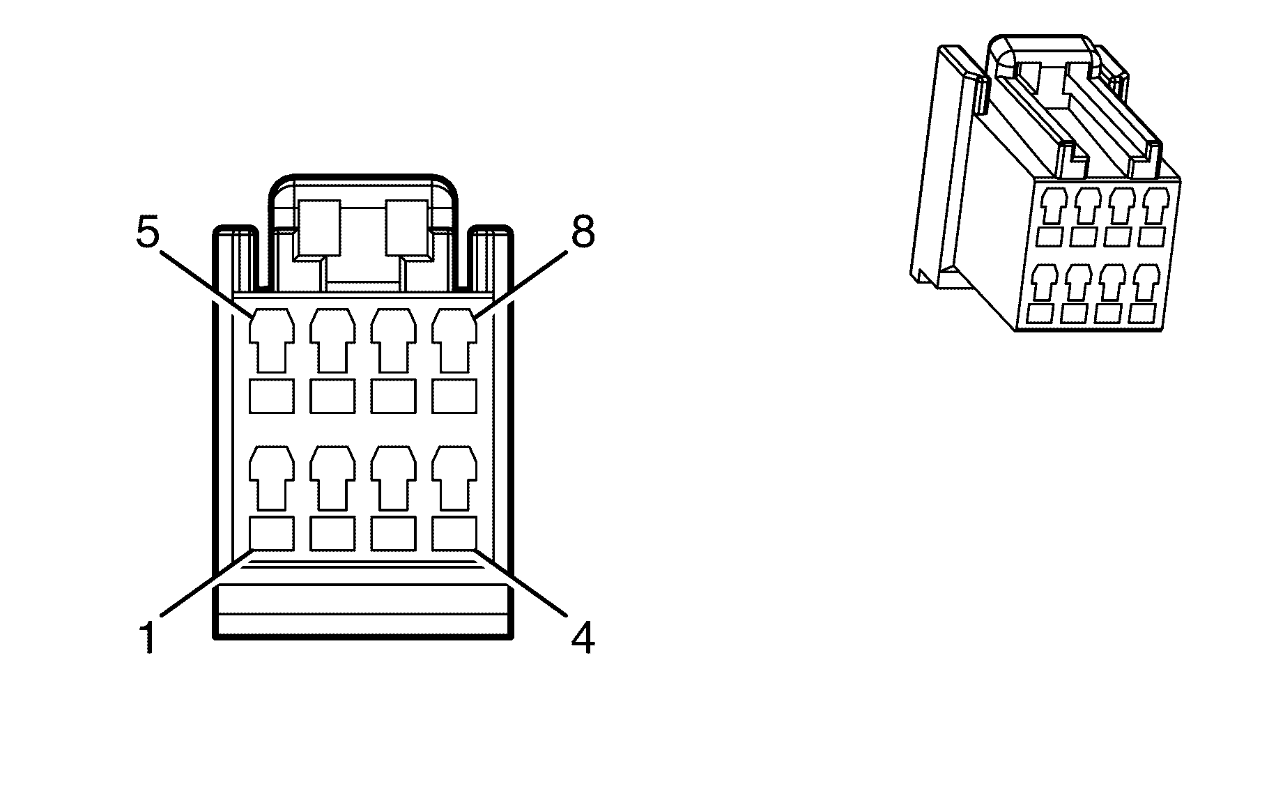
Connector Part Information
|
Terminal Part Information
|
Pin | Wire Color | Circuit No. | Function |
|---|---|---|---|
1-3 | -- | -- | Not Used |
4 | 0.3 L-GN | 1715 | Windshield Wiper Switch High Signal |
5 | -- | -- | Not Used |
6 | 0.3 OG | 94 | Windshield Washer Switch Signal |
7 | 0.3 L-BU | 1714 | Windshield Wiper Switch Low Signal |
8 | 0.3 BK/WH | 1251 | Ground |
Yaw and Lateral Accelerometer Sensor
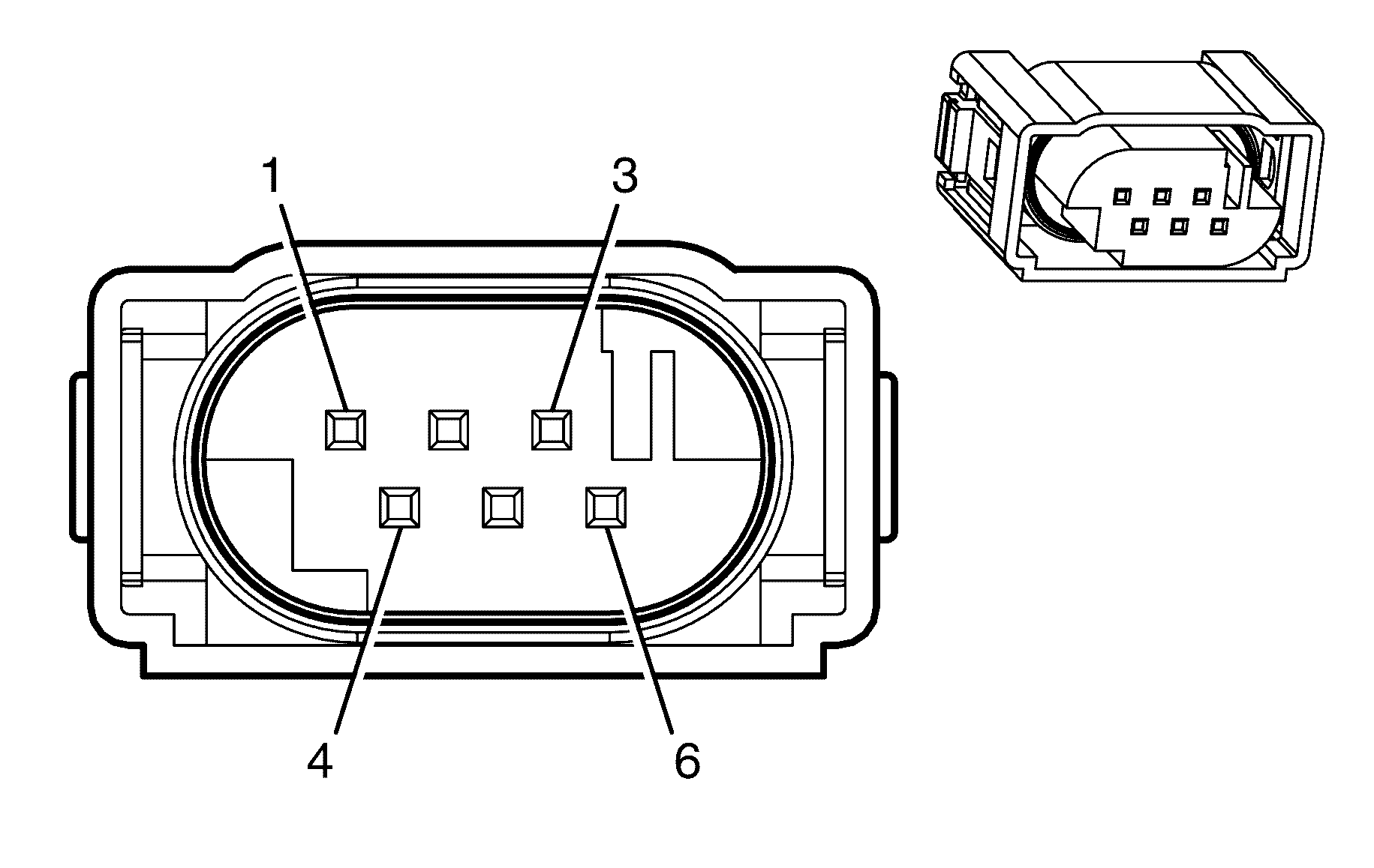
Connector Part Information
|
Terminal Part Information
|
Pin | Wire Color | Circuit No. | Function |
|---|---|---|---|
1 | 0.5 D-GN | 2087 | 5-V Reference |
2 | 0.5 L-GN/BK | 5352 | Yaw Rate Sensor Test Control |
3 | 0.5 L-BU | 5986 | Communication Enable Relay Supply Voltage |
4 | 0.5 BN/WH | 2086 | Yaw Rate Signal |
5 | 0.5 PU/WH | 1699 | Combined Vehicle Inertial Sensor Signal |
6 | 0.5 BK/BU | 2088 | Low Reference |
