For 1990-2009 cars only
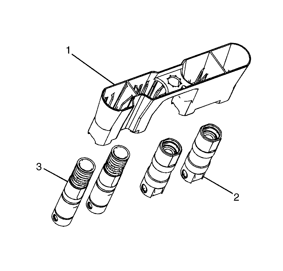
- Lubricate the valve lifters (2 and 3) with clean engine oil.
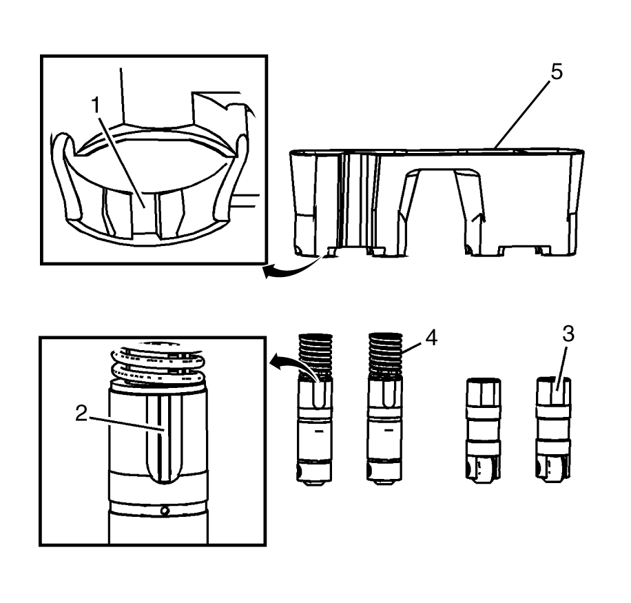
- Insert the valve lifters (3 and 4) into the lifter guides (5).
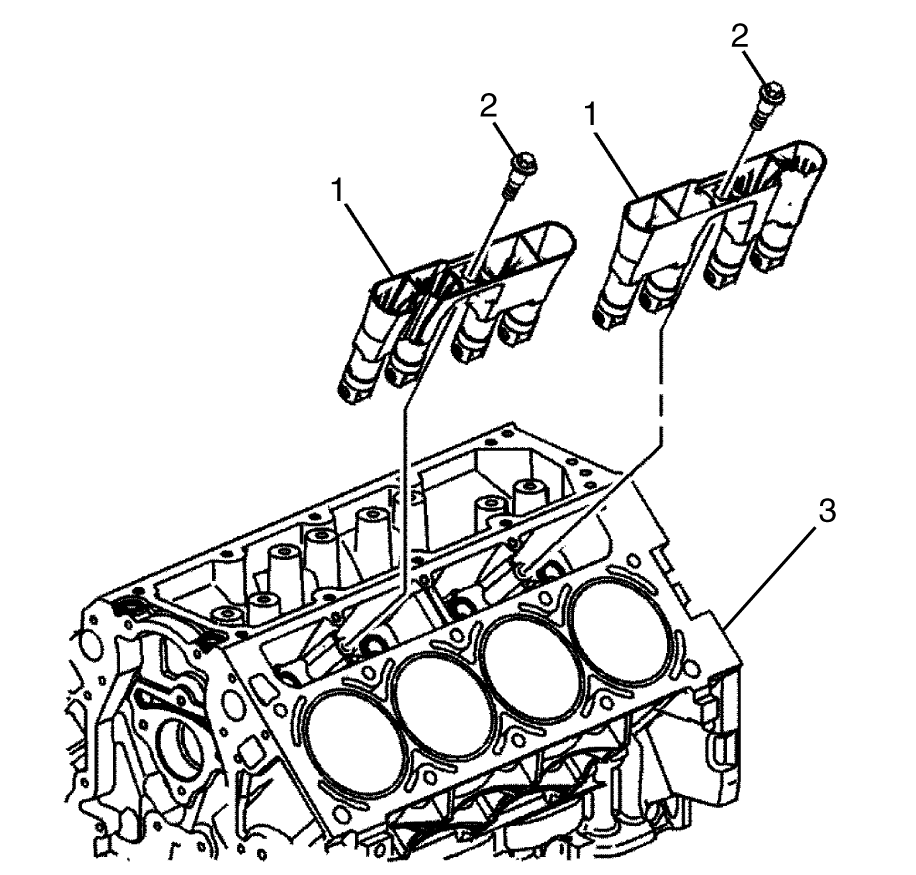
- Lubricate the valve lifter bores in the cylinder block (3) with clean engine oil.
- Install the valve lifters and guide assembly (1) to the cylinder block (3).
- Install the valve lifter guide to cylinder block retaining bolts (2).

Important:
• When using the valve lifters (2 and 3) again, install the lifters (2 and 3)
to their original locations. • If camshaft replacement is required, the valve lifters (2 and 3)
must also be replaced. • Each of the 4 valve guide assemblies will contain 2 cylinder
deactivation valve lifters (3) and 2 non-cylinder deactivation
valve lifters (2). • With the lifters (2 and 3) and guides (1)
correctly installed, cylinders 1, 4, 6, and 7 lifter bores will each contain 2 cylinder
deactivation valve lifters (3).

| • | Align the flat area on the top of the non-cylinder deactivation management lifter (3) with the flat area in the lifter guide (5) bore. Push the lifter (3) completely into the guide (5) bore. |
| • | The cylinder deactivation lifters (4) are to be installed into the guide (5), with the notch in the guide (1) aligned with the raised area (2) of the lifter (4). |

Notice: Refer to Fastener Notice in the Preface section.
Tighten
Tighten the bolts to 10 N·m (89 lb in).
