Removal Procedure
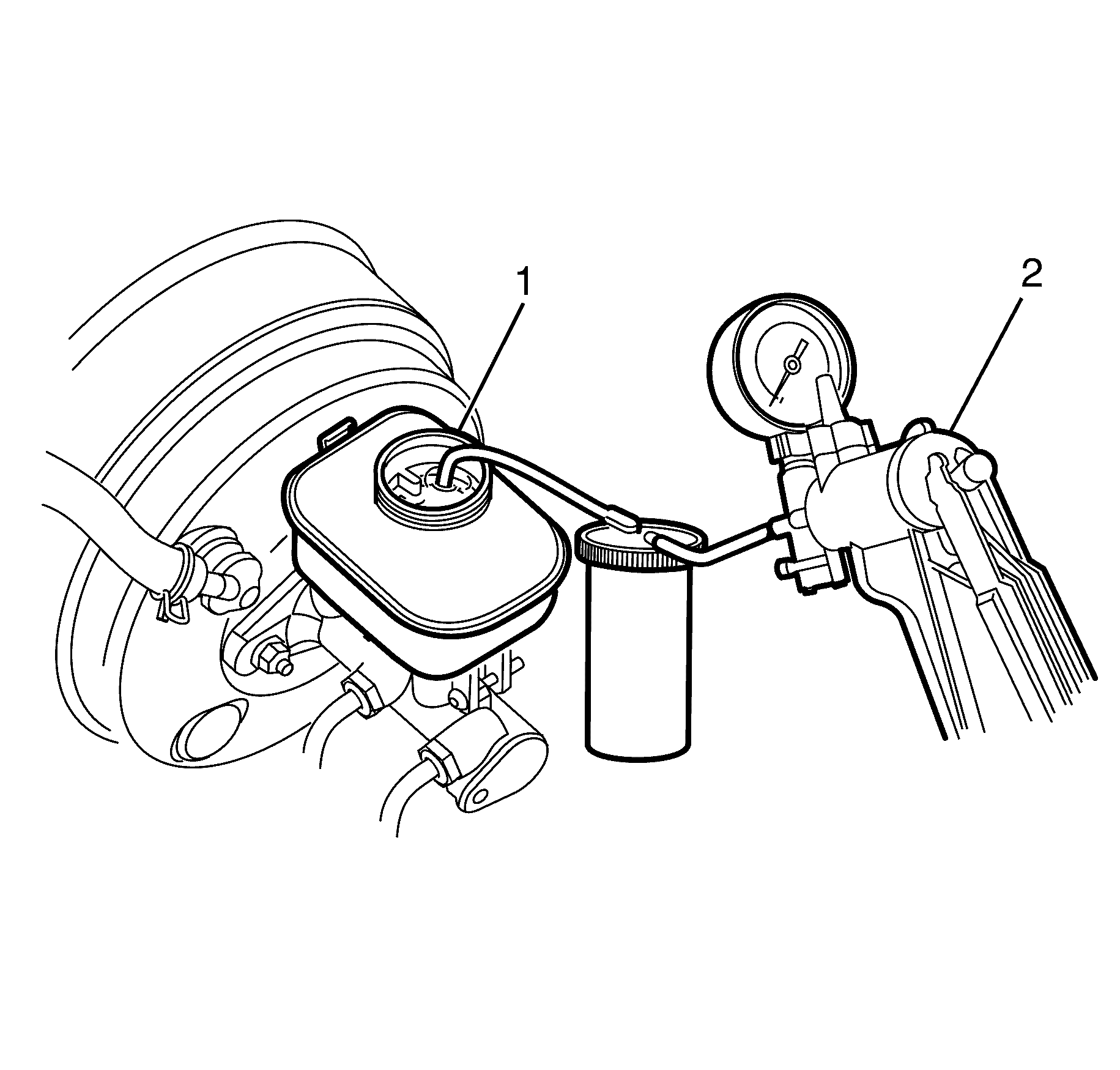
- Inspect the fluid level in the brake master cylinder reservoir (1).
- Raise and support the vehicle. Refer to Lifting and Jacking the Vehicle .
- Remove the front wheels. Refer to Tire and Wheel Removal and Installation .
- Remove the front brake caliper. Refer to Front Brake Caliper Replacement .
- Support the brake caliper with heavy mechanic's wire or equivalent.
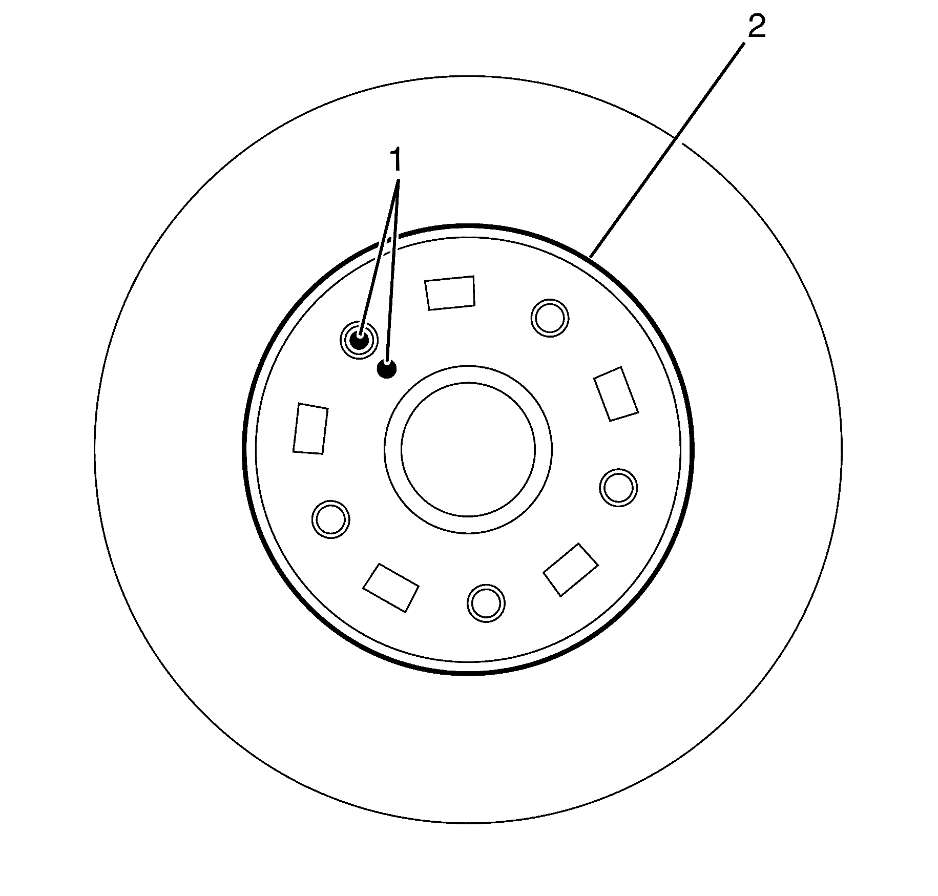
- Matchmark the position of the brake disc (2) to the wheel studs (1).
- Remove the brake disc (2).
Caution: Refer to Safety Glasses Caution in the Preface section.
Caution: Refer to Brake Fluid Caution in the Preface section.
Caution: Refer to Vehicle Lifting Caution in the Preface section.
Caution: Refer to Brake Dust Caution in the Preface section.
Caution: Refer to Brake Fluid Irritant Caution in the Preface section.
Notice: Refer to Brake Fluid Effects on Paint and Electrical Components Notice in the Preface section.
Notice: When adding fluid to the brake master cylinder reservoir, use only Holden specification number HN 1796 (Super DOT 4/DOT 4 Plus) brake fluid from a clean, sealed brake fluid container. The use of any type of fluid other than the recommended type of brake fluid may cause contamination which may result in damage to the internal rubber seals and/or rubber linings of hydraulic brake system components.

| • | If the brake fluid level is midway between the maximum-fill level and the minimum allowable level, no brake fluid needs to be removed from the master cylinder reservoir before proceeding. |
| Important: DO NOT reuse the removed fluid. |
| • | If the brake fluid level is higher than midway between the maximum-fill level and the minimum allowable level, syphon the brake fluid to the midway point using a hand vacuum pump (2) before proceeding. |
Important: DO NOT disconnect the hydraulic brake flexible hose from the brake caliper otherwise complete bleeding of the braking system will be necessary.
Notice: Support the brake caliper with heavy mechanic wire, or equivalent, whenever it is separated from its mount and the hydraulic flexible brake hose is still connected. Failure to support the caliper in this manner will cause the flexible brake hose to bear the weight of the caliper, which may cause damage to the brake hose and in turn may cause a brake fluid leak.

Important: The brake disc to hub relationship is indexed during production. Mark the relationship of the brake disc to a wheel stud end for installation to minimise the potential of brake shudder.
Important: If the brake disc is being removed to be machined or replaced to rectify brake shudder, or if brake disc to hub matching is not evident, the brake disc to the hub must be indexed. Refer to Brake Rotor Assembled Lateral Runout Correction - Indexing .
Installation Procedure
- Clean any rust or corrosion from the mating surface of the hub/axle flange and mounting surface of the brake disc.
- Inspect the mating surfaces of the hub/axle flange and the brake disc to make sure that there are no foreign particles or debris remaining.
- Install the brake disc (2) to the hub/axle flange.
- If the brake disc (2) was removed and installed as part of a brake system repair, measure the assembled LRO of the brake disc (2) to make sure optimum performance of the disc brakes. Refer to Brake Rotor Assembled Lateral Runout Measurement .
- If the brake disc (2) assembled LRO measurement exceeds the specification, bring the LRO to within specifications. Refer to Brake Rotor Assembled Lateral Runout Correction .
- Remove the heavy mechanic's wire or equivalent support from the brake caliper.
- Install the front brake caliper. Refer to Front Brake Caliper Replacement .
- Install the front wheels. Refer to Tire and Wheel Removal and Installation .
- Lower the vehicle to the ground.
- With the ignition OFF, gradually apply the brake pedal to approximately 2/3 of its travel distance.
- Slowly release the brake pedal.
- Repeat steps 10 and 11 until a firm brake pedal application is obtained. This will correctly seat the brake caliper pistons and brake pads.
- Fill the master cylinder reservoir to the correct level. Refer to Master Cylinder Reservoir Filling .
- If the brake rotor was refinished or replaced, or if new brake pads were installed, burnish the brake pads and brake rotors. Refer to Brake Pad and Rotor Burnishing .
Important: Whenever the brake disc has been separated from the hub/axle flange, any rust or contaminants should be cleaned from the hub/axle flange and the brake disc mating surfaces. Failure to do this may result in too much assembled lateral runout (LRO) of the brake disc, which may lead to brake pulsation.

Important: Use the matchmark (1) made prior to removal for correct orientation to the flange.
Notice: Make sure the brake hose is not twisted or kinked after installation. Damage to the hose could result.
