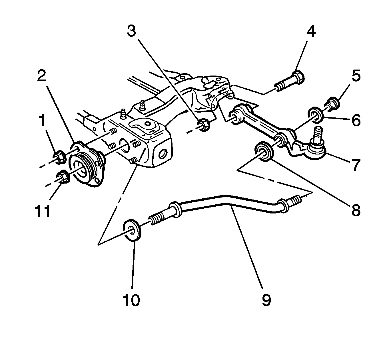
For 1990-2009 cars only
Tools Required
J 42188 Ball Joint Separator
Removal Procedure
- Raise and support the vehicle. Refer to Lifting and Jacking the Vehicle in General Information.
- Remove the front tire and wheel assembly. Refer to Tire and Wheel Removal and Installation in Tires and Wheels.
- Turn the steering wheel in order to access the control arm ball joint stud.
- Remove and discard the nut that retains the control arm ball joint stud to the knuckle.
- Use the J 42188 , or equivalent, in order to separate the control arm ball joint stud from the knuckle.
- Use a block of wood in order to push the control arm (7) away from the knuckle.
- Remove and discard the nut (5) that retains the control arm rod (9) to the control arm.
- Remove the washer (6) from the rod.
- Remove and discard the nut (3) that retains the control arm to the front frame.
- Remove the bolt (4) and the control arm from the front frame.
- Remove the control arm from the rod.

Important: Do not remove the retainer (8).
Installation Procedure
- Ensure the retainer (8) is on the control arm rod (9) properly.
- Install the control arm (7) to the rod.
- Install the control arm and the bolt (4) to the front frame.
- Install a NEW nut (3) to the bolt in order to retain the control arm to the front frame.
- Install the washer (6) to the rod.
- Install a NEW nut (5) to the rod.
- Position a jack and a block of wood below the control arm ball joint.
- Raise the jack in order to support the control arm.
- Install the control arm ball joint stud to the knuckle.
- Install a NEW nut to the control arm ball joint stud.
- Remove the jack and the block of wood.
- Lower the vehicle onto an alignment rack.
- With the weight of the vehicle on the tire and wheel assemblies, push down on the front bumper 3 times in order to stabilize the suspension.
- Tighten the nut that retains the control arm to the front frame.
- Tighten the nut that retains the control arm rod to the control arm.
- Measure the wheel alignment. Adjust the alignment if necessary. Refer to Wheel Alignment Measurement in Wheel Alignment.

Important: Do not tighten the nut yet.
Important: Do not tighten the nut yet.
Raise the jack in order to seat the control arm ball joint stud.
Notice: Refer to Fastener Notice in the Preface section.
Tighten
Tighten the nut to 60 N·m (44 lb ft).
Tighten
Tighten the nut to 98 N·m (72 lb ft).
Tighten
Tighten the nut to 103 N·m (76 lb ft).
