For 1990-2009 cars only
Tools Required
J 45059 Angle Meter
Removal Procedure
- Raise and support the vehicle. Refer to Lifting and Jacking the Vehicle in General Information.
- Remove the front tire and wheel assembly. Refer to Tire and Wheel Removal and Installation in Tires and Wheels.
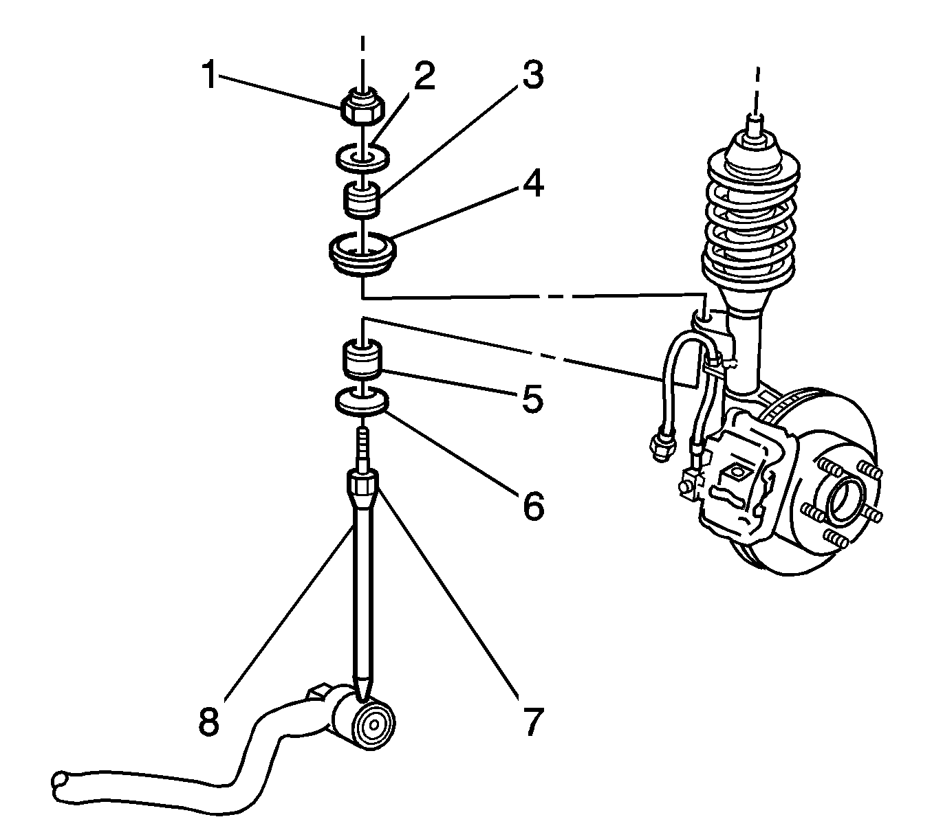
- Use a wrench in order to hold the stabilizer shaft link upper stud (7).
- Remove the upper nut (1).
- Remove the upper washer (2).
- Remove the upper insulator (3).
- Remove the retainer (4).
- Separate the wheel speed sensor harness and the insulator from the strut bracket.
- Turn the sleeve that retains the brake hose to the strut bracket.
- Align the flats on the sleeve with the strut bracket opening.
- Separate the brake hose from the strut bracket.
- Position a jack and a block of wood below the control arm ball joint.
- Raise the jack in order to support the control arm.
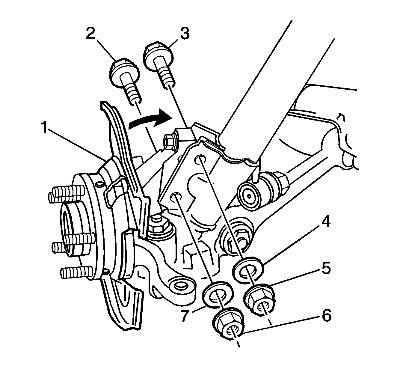
- Remove and discard the 2 nuts (5,6).
- If equipped, remove the 2 washers (4,7).
- Remove and discard and the 2 bolts (2,3).
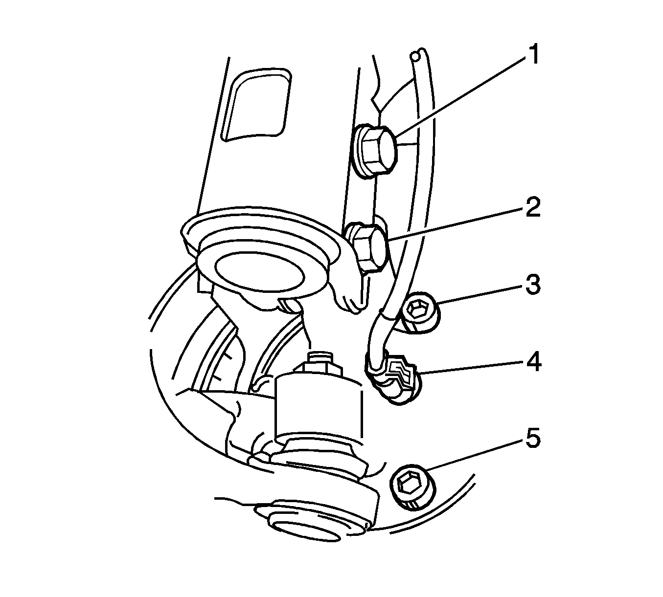
- Lift the locking tab on the wheel speed sensor connector (4).
- Disconnect the wheel speed sensor connector from the knuckle.
- Separate the knuckle from the strut.
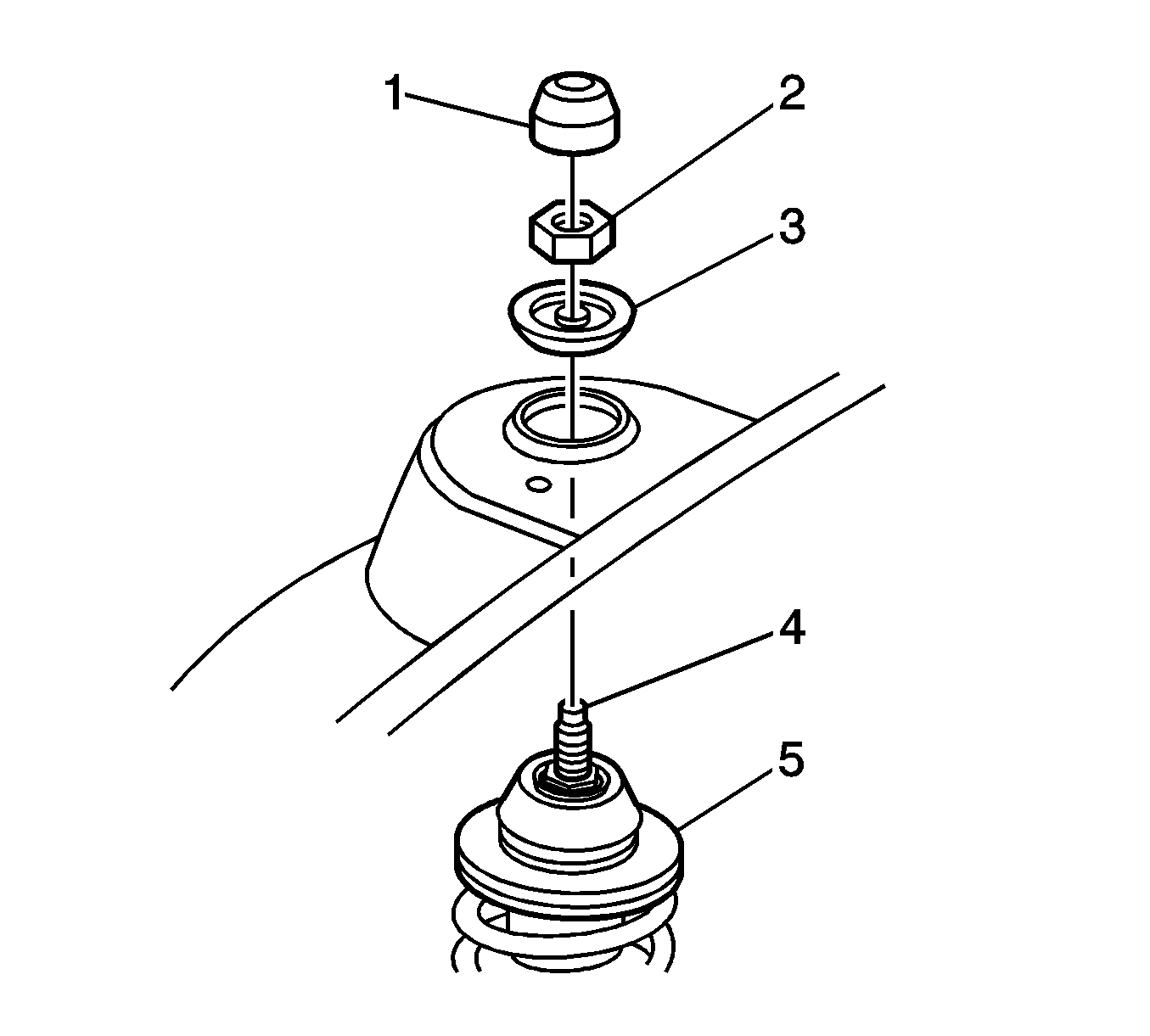
- Remove the strut nut cap (1).
- Use a wrench in order to hold the end of the strut rod shaft (4).
- Remove and discard the strut nut (2).
- Remove the strut bumper stop (3).
- Lower the strut assembly.
- Remove the stabilizer shaft link from the strut bracket.
- Remove the strut assembly from the vehicle.
Installation Procedure
- Tighten the strut mount nut (1).
- Install the top of the stabilizer shaft link to the bracket on the strut assembly.
- Install the strut assembly to the strut tower.
- Install the strut bumper stop (3).
- Install a NEW strut nut (2).
- Install the 2 NEW bolts in order to retain the strut to the knuckle.
- Install the 2 washers to the bolts.
- Install the 2 NEW nuts to the bolts.
- Use a wrench in order to hold the end of the strut rod shaft (4).
- Tighten the nut that retains the strut to the strut tower.
- Install the strut nut cap (1).
- Remove the jack and the block of wood.
- Align the flats on the brake hose sleeve with the strut bracket opening.
- Install the brake hose to the strut bracket.
- Turn the sleeve that retains the brake hose to the strut bracket.
- Connect the wheel speed sensor connector (4).
- Verify the locking tab on the connector is secure.
- Install the wheel speed sensor harness and the insulator to the strut bracket.
- Install the retainer (4).
- Install the upper insulator (3).
- Install the upper washer (2).
- Use a wrench in order to hold the stabilizer shaft link upper stud (7).
- Install the upper nut.
- Install the front tire and wheel assembly. Refer to Tire and Wheel Removal and Installation in Tires and Wheels.
- Lower the vehicle onto an alignment rack in order to place the weight of the vehicle onto the tires.
- Push down on the front bumper 3 times in order to stabilize the suspension.
- Measure the wheel alignment. Refer to Wheel Alignment Measurement in Wheel Alignment.
- Adjust the alignment to the specifications if necessary. Refer to Wheel Alignment Specifications in Wheel Alignment.
- Tighten the 2 nuts that retain the strut to the knuckle.
- Tighten the nuts to 100 N·m (74 lb ft).
- Use the J 45059 in order to tighten the nuts an additional 90 degrees.
Notice: Refer to Fastener Notice in the Preface section.
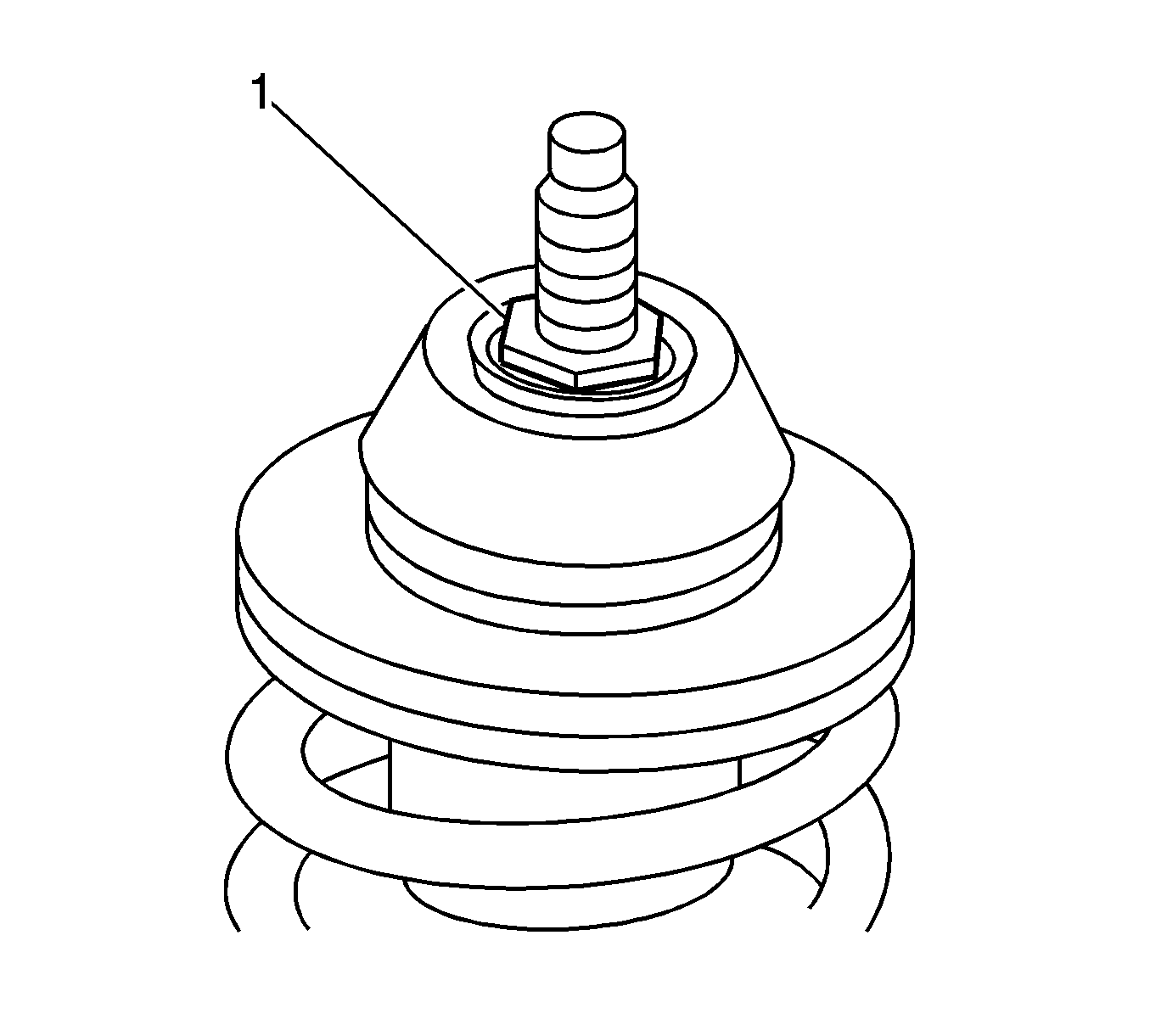
Tighten
Tighten the nut to 78 N·m (58 lb ft).

Important: Do not tighten the strut nut yet.
Tighten
Tighten the 2 nuts to 85 N·m (63 lb ft).
Tighten
Tighten the nut to 55 N·m (41 lb ft).


Important: Do not use power tools on the upper nut (1).
Tighten
Tighten the nut to 16 N·m (12 lb ft).
Important: The camber adjustment screw has thread sealant in the form of micro-encapsulation.
Rotate the camber adjustment screw in order to adjust the front camber.
Tighten
