For 1990-2009 cars only
Tools Required
| • | J 6627-A Tie Rod Puller |
| • | J 42066 Rear Hub Holding Tool |
| • | J 45059 Angle Meter |
Removal Procedure
- Raise and support the vehicle. Refer to Lifting and Jacking the Vehicle in General Information.
- Remove the tire and wheel assembly. Refer to Tire and Wheel Removal and Installation in Tires and Wheels.
- Install the J 42066 , or the equivalent tool, and 2 wheel nuts onto 2 studs in order to prevent the hub from turning.
- Tie wire to the upper shock mount and to the wheel drive shaft (1) in order to support the wheel drive shaft.
- Remove the bolts (2) and the retaining plates that retain the outer constant velocity joint to the drive shaft flange.
- Separate the wheel drive shaft from the drive shaft flange.
- Loosen the nut that retains the stabilizer shaft to the shaft link.
- Remove the nut and the bolt that retain the stabilizer shaft link to the lower control arm.
- Loosen the nut that retains the outer adjustment link to the control arm.
- Use the J 6627-A , or equivalent, in order to separate the stud from the control arm.
- Remove and discard the nut from the stud.
- Position the adjustment link assembly away from the control arm.
- Position a jack with a block of wood under the control arm.
- Raise the jack slightly in order to reduce the spring load on the control arm.
- Remove the bolt (2) and the washer from the shock absorber (1).
- Separate the shock absorber from the control arm (3).
- Lower the jack and the control arm.
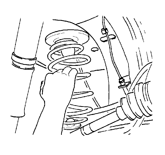
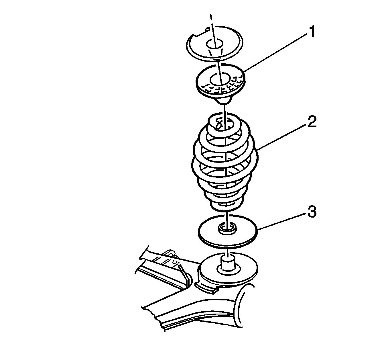
- Push down gently on the control arm and remove the spring and the 2 insulators.
- Remove the insulators from the spring.
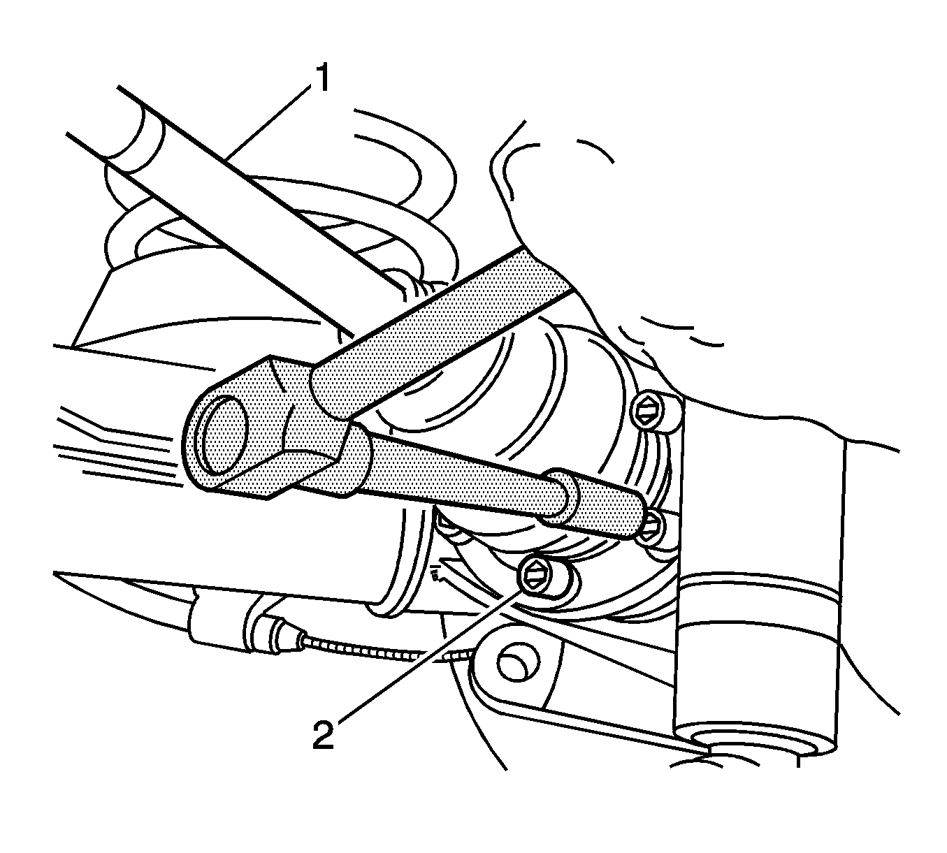
Important: DO NOT allow the wheel drive shaft to hang freely.
Position the top of the nut with the top of the outer adjustment link stud.
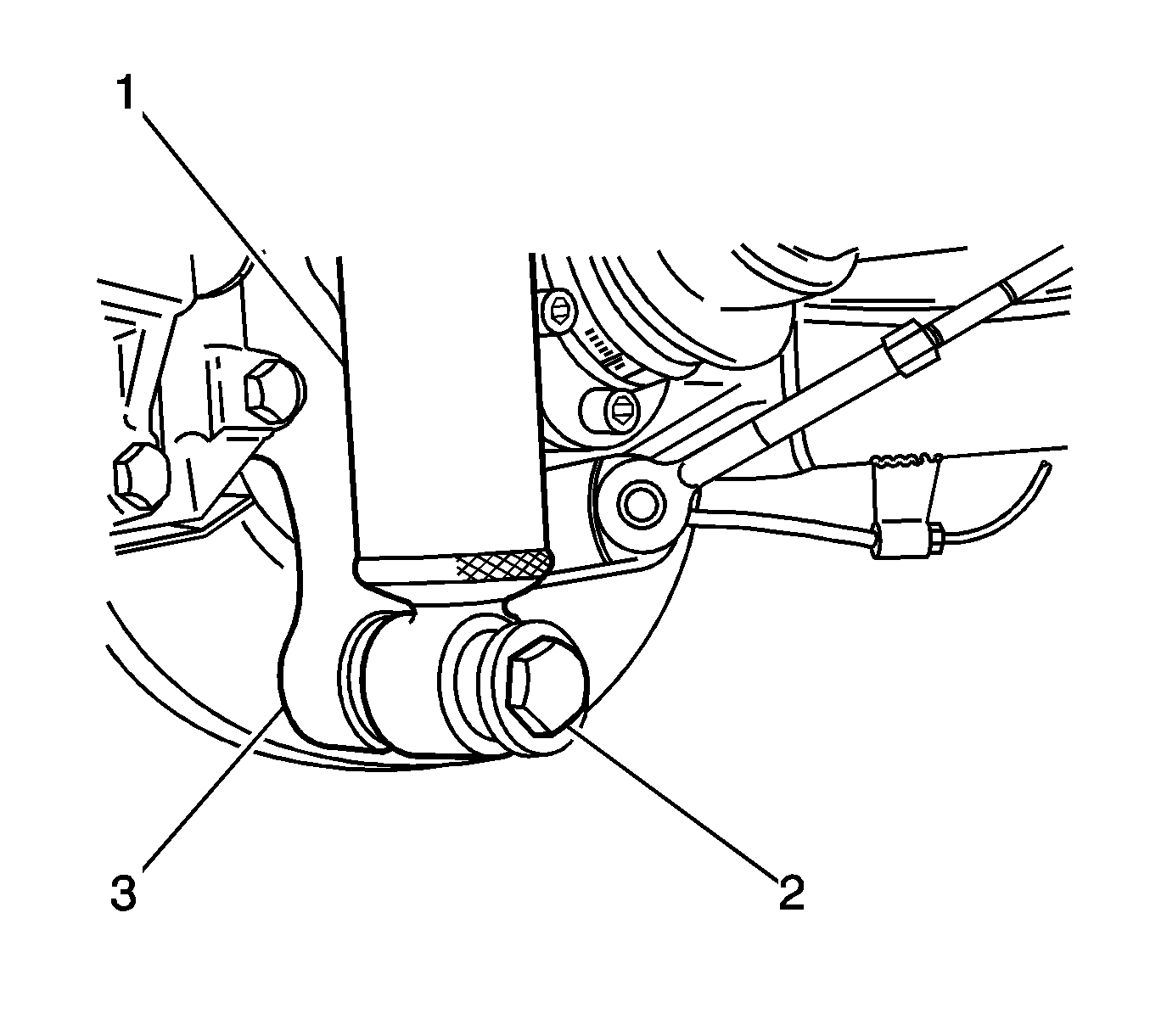
Important: Do not pull on the brake hose.
Installation Procedure
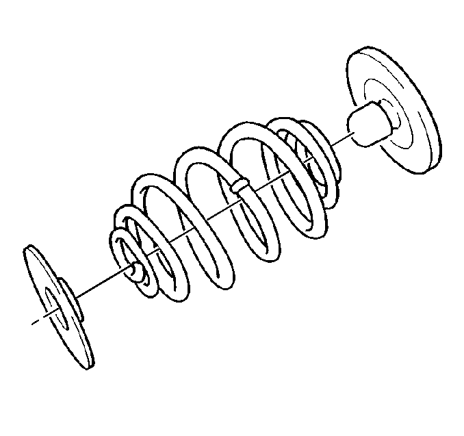
- Install the lower insulator (3) to the control arm.
- Install the upper insulator (1) to the spring (2).
- Push down gently on the control arm. Install the spring and the upper insulator to the lower insulator.
- Adjust the position of jack in order to align the control arm and the shock absorber.
- Install the washer and the bolt in order to retain the shock absorber to the control arm.
- Install the nut and the bolt in order to retain the stabilizer shaft link to the control arm.
- Install the outer adjustment link stud and a NEW nut to the control arm.
- Remove the jack and the wood from the control arm.
- Install the J 42066 , or the equivalent tool, and 2 wheel nuts onto 2 studs in order to prevent the hub from turning.
- Install the retainers and the bolts (2) in order to retain the outer constant velocity joint to the drive shaft flange.
- Tighten the bolts to 50 N·m (37 lb ft).
- Use the J 45059 in order to tighten the bolts an additional 68 degrees.
- Remove the J 42066 , or the equivalent tool, and 2 wheel nuts from the 2 studs.
- Remove the wire supporting the wheel drive shaft (1).
- Install the tire and wheel assembly. Refer to Tire and Wheel Removal and Installation in Tires and Wheels.
- Lower the vehicle.
- With the weight of the vehicle on the tire and wheel assemblies, bounce the rear of the vehicle several times in order to stabilize the rear suspension.
- Tighten the stabilizer shaft link nuts.
- Tighten the bolt that retains the shock absorber to the control arm.
- Tighten the nut that retains the outer adjustment link to the control arm.
- Measure the wheel alignment. Adjust the alignment if necessary. Refer to Wheel Alignment Measurement in Wheel Alignment.
Important: Do not tighten the bolt yet. The weight of the vehicle must be on the tire and wheel assemblies before tightening the suspension fasteners.
Important: Do not tighten the nut or the bolt yet.
Important: Do not tighten the nut yet.
Notice: Refer to Fastener Notice in the Preface section.

Tighten
Tighten
Tighten the nuts to 98 N·m (72 lb ft).
Tighten
Tighten the bolt to 115 N·m (85 lb ft).
Tighten
Tighten the nut to 63 N·m (46 lb ft).
