Removal Procedure
- Remove the front suspension support brace. Refer to Front Suspension Support Brace Replacement .
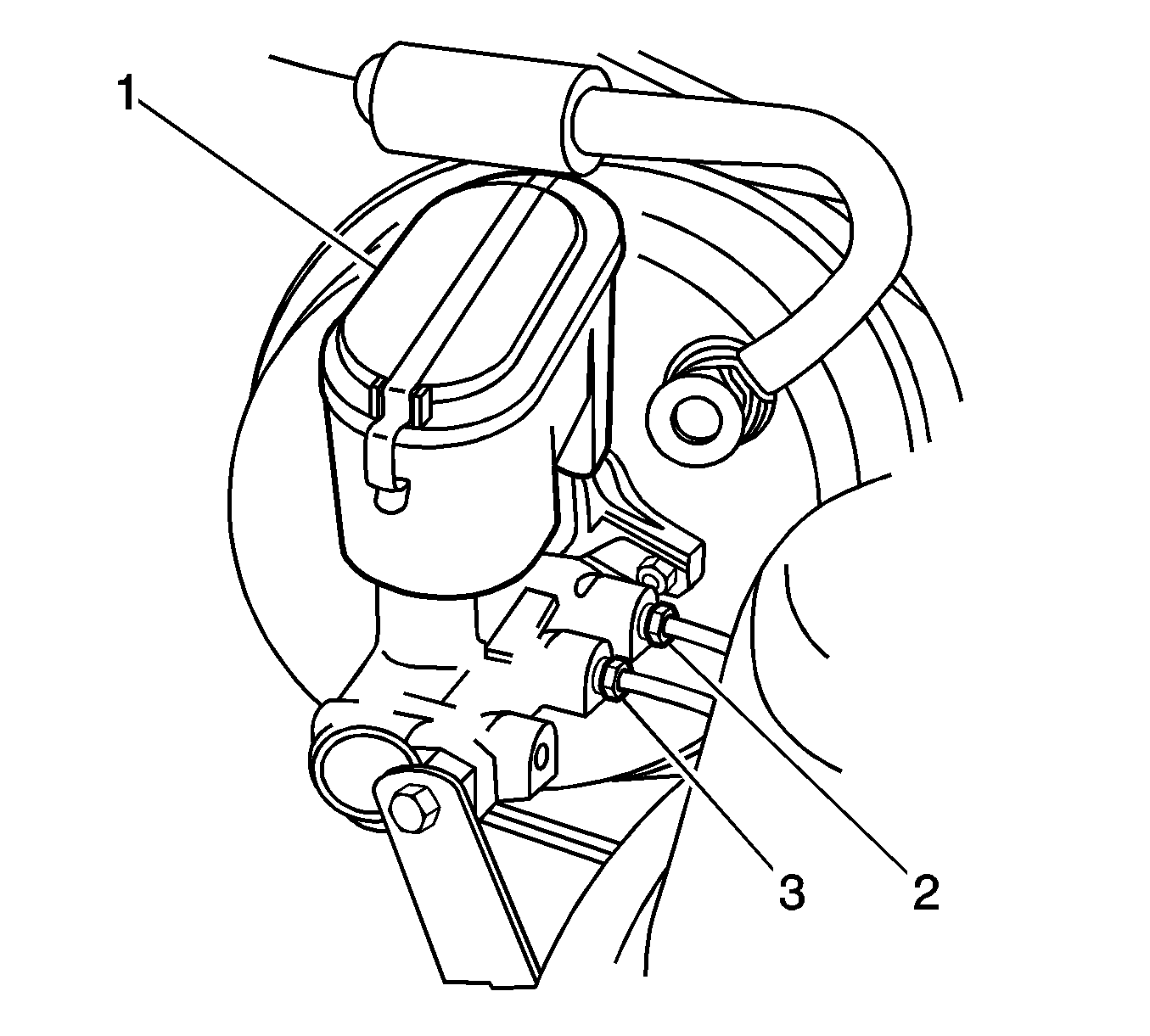
- Clean the outside of the brake master cylinder reservoir and the reservoir cap (1).
- Clean the master cylinder.
- Clean the brake pipes around the master cylinder.
- Disconnect the brake fluid level differential switch connector.
- Place a container below the master cylinder in order to catch the brake fluid.
- Remove the reservoir cap.
- Remove the cap seal.
- Remove the brake fluid with a syringe.
- Loosen the 2 flare nuts (2, 3) and separate the 2 brake pipes from the master cylinder.
- Install caps or plugs to the brake pipes in order to prevent brake fluid loss and contamination.
- Install caps or plugs to the master cylinder ports in order to prevent contamination.
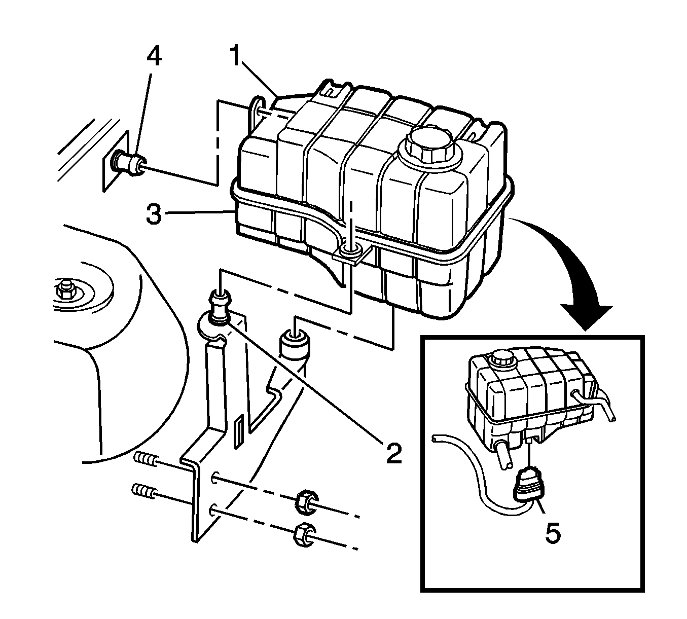
- Verify the engine coolant surge tank (1) is cool enough to touch.
- Pivot the surge tank in order to remove the surge tank from the rear anchor plate (2).
- Pivot the surge tank inboard in order to remove the surge tank from the left anchor plate (4).
- Disconnect the coolant level switch connector (5).
- Remove the powertrain control module. Refer to Powertrain Control Module Replacement .
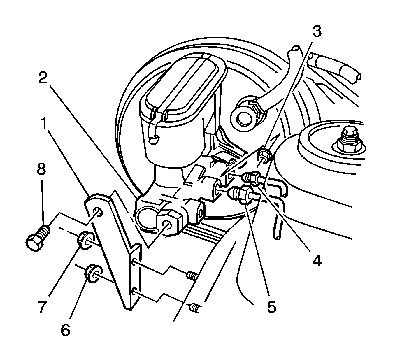
- Remove the bolt (8) from the master cylinder bracket (1).
- Remove the 2 nuts (6,7) from the bracket.
- Remove the bracket.
- Remove the 2 nuts that retain the master cylinder to the vacuum brake booster.
- Remove the master cylinder assembly.

Caution: Refer to Brake Fluid Irritant Caution in the Preface section.
Notice: Refer to Brake Fluid Effects on Paint and Electrical Components Notice in the Preface section.

Important: Do not remove the hoses or the cap from the surge tank.

Important: Do not push the booster push rod or the brake pedal.
Installation Procedure
- Install the master cylinder assembly (2) to the vacuum brake booster.
- Install the 2 nuts to the booster studs.
- Install the bracket (1).
- Install the bolt (8) and the nuts (6, 7).
- Install the powertrain control module. Refer to Powertrain Control Module Replacement .
- Connect the coolant level switch connector.
- Install the coolant surge tank to the left anchor bracket.
- Install the surge tank to the rear anchor bracket.
- Place a container under the master cylinder in order to catch the brake fluid.
- Remove the caps or the plugs from the brake pipes and the master cylinder.
- Push the 2 brake pipes into the master cylinder ports.
- Fill the reservoir with GM Vehicle Care® Brake and Clutch Fluid, GM P/N 88958860, or the equivalent DOT-4 brake fluid. Refer to Master Cylinder Reservoir Filling .
- Allow the fluid to drip from the ports for approximately 1 minute.
- Tighten the 2 flare nuts.
- Bleed the brakes. Refer to Hydraulic Brake System Bleeding .
- Fill the reservoir. Refer to Master Cylinder Reservoir Filling .
- Install the cap seal.
- Install the cap.
- Remove the container from below the master cylinder.
- Connect the brake fluid level differential switch connector.
- Install the front suspension support brace. Refer to Front Suspension Support Brace Replacement .

Notice: Refer to Fastener Notice in the Preface section.
Tighten
Tighten the nuts to 18 N·m (13 lb ft).
Tighten
Tighten the bolt and the nuts to 19 N·m (14 lb ft).
Caution: Refer to DOT 4 Brake Fluid Caution in the Preface section.
Notice: When adding fluid to the brake fluid reservoir or to the clutch fluid reservoir, use only Super DOT-4 or equivalent DOT-4 brake fluid from a clean, sealed container. This polyglycol brake fluid is hygroscopic and absorbs moisture. Do not use fluid from an open container that may be contaminated with water. Improper or contaminated fluid could result in damage to the system components.
Important: Ensure the brake fluid level stays above half-full.
Tighten
Tighten the 2 flare nuts (4, 5) to 14 N·m (10 lb ft).
